3a. When things don't work: Replacing Components (Battery Corrosion, PIAs, etc.)
If you have found a bad component, now comes the hard part; replacing it!
Transistors, bridge rectifiers, and most chips are not socketed.
They are soldered directly into the driver
board. Care must be taken when replacing a bad component.
Please see http://pinrepair.com/begin
for details on the basic electronics skills and tools you will need
when replacing circuit board components.
When replacing components, the object is to subject the board to the least amount of heat as
possible. Too much heat can lift or crack the board's traces. Too
little heat and you can rip out the plated-through holes when
removing the part. New
circuit boards are too expensive to replace. So you must be careful
when doing this.
To remove a bad chip, just CUT it off of the board, leaving
as much of its original lead(s) as possible. Then using
needle nose pliers, grab the chip lead in the board while heating it
with your soldering iron, and pull it out. You can clean up
the solder left behind with a desoldering tool. This is the safest
method of chip removal and should cause the least amount of
damage to the board.
When replacing chips, alway install a socket. Buy good quality sockets.
Avoid "Scanbe" sockets at all costs! A good dual sided socket is preferred.
Battery Corrosion.
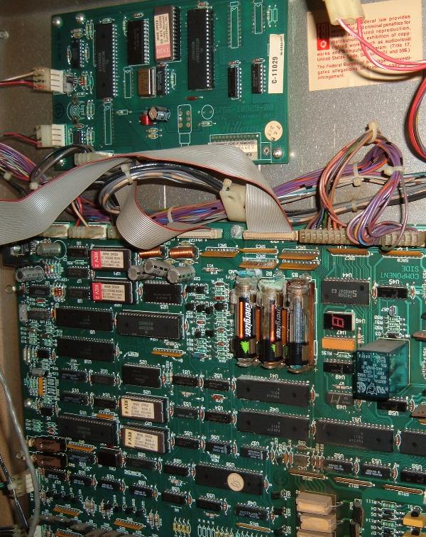
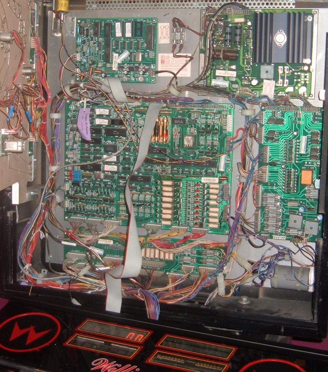
One BIG problem with system11 games are the batteries. The CPU board has mounted
at the top center a 3-AA battery pack. This keeps audits, adjustments and high scores
in memory when the game is powered off. But if the batteries are neglected and grow
old, they can leak their corrosive fluids on the CPU board, ruining the board.
Batteries left to corrode on a High Speed. At first it doesn't look too bad...
|
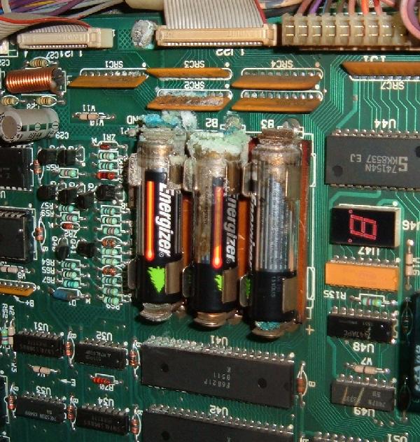
...A closer look and you can see the corrosion has really taken its toll.
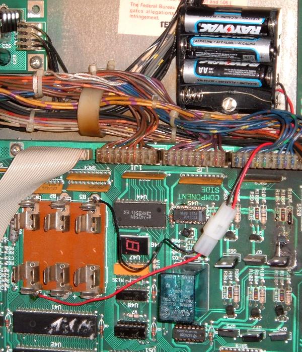
The original battery pack will be removed, the CPU board bead blasted in this area,
and the corroded traces/components replaced. Here PIA u41 will be replaced, along
with resistor networks SRC1-SRC3.
|
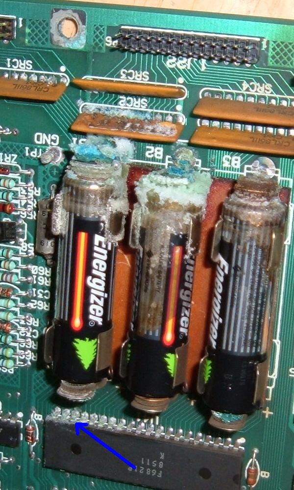
...Even closer. That's pretty nasty battery corrosion. The good news is
this is "fresh" corrosion that hasn't dug in deep on the CPU board. Yes it
will require some major bead blasting to correct, but it should clean up OK.
|
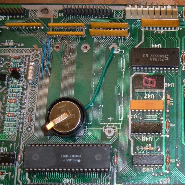
Here's the board after bead blasting. Many of the traces underneath the
battery holder were destroyed by corrosion, and had to be re-run with wire wrap
style wire. PIA u41 was removed, the board under this chip bead blasted, and
a socket installed. SRC1-SRC3 were replaced with SR resistor networks.
Finally a coin style battery was installed.
|
Battery corrosion can be a very serious problem. If a game is stored long
enough with leaking batteries, the CPU board can be completely ruined.
These are expensive board too (around $300 or more.) Luckily Rottendog Amusements
has reissued the sys11a-11c CPU board (but no sys11, as used on High Speed.)
An excellent approach to preventing battery corrosion is to mount a remote
battery pack off the CPU board. This way if the batteries leak, you only
ruin a $5 battery holder instead of a $250 CPU board. I highly suggest this
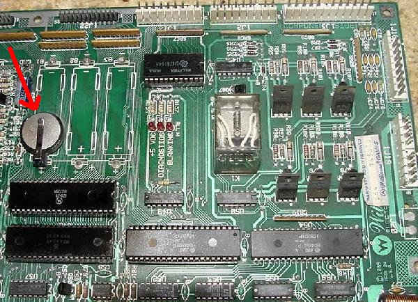
approach. Another idea is to use a socketed coin style battery CR 2032. These work
great on system11 games, last a very long time (up to 10 years), and don't
leak. This is the approach I have been taking lately. The cost of the battery
is about $1, and the socket is also about $1 (See BG Micro
as an inexpensive place for these batteries and holders.) This is about the same cost
as a remote battery pack and three AA batteries, and it's a cleaner installation.
A remote AA battery pack installed in a system11 game.
|
A cr2032 coin battery and socket installed on a system11b CPU board.
|
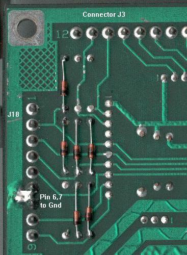
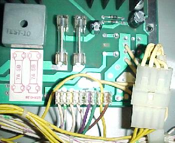
Battery Corrosion and Resistor/Capacitor SRC1-SRC5 Networks.
Just north of the batteries are SIP (single inline) 8r 8c 10 pin resistor/capacitor networks.
These can often be compromised by battery corrosion. Unfortunately these are
difficult to find (4.7k ohm with a 470 PFD capacitor network.)
They can be replaced with a straight SR resistor network (with no capacitors).
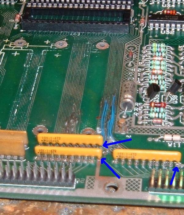
If this is done, a "4.7k ohm x 9R" bussed resistor network can be used,
but it must be installed correctly! This bussed
resistor network will have ten pins, with one "common" pin (the pin with the "dot").
The common pin 1 of the resistor network must go in the board's pin 1 (for +5 volts).
BUT the last pin 10 of the resistor network leg should be cut and not installed in the CPU
board, because this pin on the CPU board goes to ground (for the capacitor part of the
SRC, which we are not using since we're installing a SR and not a SRC).
Replaced SRC networks with 4.7k 10 pin bussed SR networks at SRC1-SRC3.
Note pin #10 of the new SR network is cut and not installed.
|
Battery Corrosion Around the PIAs.
If battery corrosion has happened to a system11 CPU board, often the traces
around the battery pack are compromised.
If this has happened, there are a number of components directly below (and *underneath*) the battery
holder than are often affected. For this reason, and to aid in the replacement
of PIA chips for other reasons, I will list where these large 40 pin PIA chips
connect below. This way you can "buzz out" the chip legs and make sure they still connect
to their intended components (because often battery corrosion can eat these traces).
If even a single trace to one of the PIA or support chips is broken, this can
cause the entire CPU board to not "boot", or for game functions to not work.
(For example, a score display segment to not light.)
PIA and Support Chip Connections.
Here's a list of all the PIAs connections (except for the sys11-sys11b sound PIA).
PIA U41 (display)
- pin 1 = gnd
- pin 2 (pa0) = src5 pin 2, j22 pin 11
- pin 3 (pa1) = src5 pin 3, j22 pin 12
- pin 4 (pa2) = src5 pin 4, j22 pin 13
- pin 5 (pa3) = src5 pin 5, j22 pin 14
- pin 6 (pa4) = src5 pin 6, j22 pin 15
- pin 7 (pa5) = src5 pin 7, j22 pin 16
- pin 8 (pa6) = src5 pin 8, j22 pin 17
- pin 9 (pa7) = src5 pin 9, j22 pin 18
- pin 10 (pb0) = src2 pin 2, j22 pin 19
- pin 11 (pb1) = src2 pin 3, j22 pin 20
- pin 12 (pb2) = src2 pin 4, j22 pin 21
- pin 13 (pb3) = src2 pin 5, j22 pin 22
- pin 14 (pb4) = src2 pin 6, j22 pin 23
- pin 15 (pb5) = src2 pin 7, j22 pin 24
- pin 16 (pb6) = src2 pin 8, j22 pin 25
- pin 17 (pb7) = src2 pin 9, j22 pin 26
- pin 18 (cb1) = src1 pin 2, j21 pin 11
- pin 19 (cb2) = u49 pin 5, sr19 pin 7
- pin 20 = +5
- pin 21 (r/w) = pin 21 on all PIAs, j21 pin 17, u36 pin 1, u13 pin 18, u16 pin 1
- pin 22 (cs0) = pin 22 on all PIAs
- pin 23 (cs2) = u37 pin 12
- pin 24 (cs1) = pin 24 on all PIAs (a13 address bus), u14 pin 6
- pin 25 (E) = pin 25 on all PIAs, u32 pin 10, u35 pin 1, u35 pin 3, u32 pin 13, u29 pin 10, u11 pin 18, j21 pin 19
- pin 26 (d7) = pin 26 on all PIAs, u16 pin 9, u28 pin 8, u25 pin 17, u26 pin 19, u27 pin 19
- pin 27 (d6) = pin 27 on all PIAs, u16 pin 8, u28 pin 13, u25 pin 16, u26 pin 18, u27 pin 18
- pin 28 (d5) = pin 28 on all PIAs, u16 pin 7, u28 pin 14, u25 pin 15, u26 pin 17, u27 pin 17
- pin 29 (d4) = pin 29 on all PIAs, u16 pin 6, u28 pin 7, u25 pin 14, u26 pin 16, u27 pin 16
- pin 30 (d3) = pin 30 on all PIAs, u16 pin 5, u28 pin 17, u25 pin 13, u26 pin 15, u27 pin 15
- pin 31 (d2) = pin 31 on all PIAs, u16 pin 4, u28 pin 4, u25 pin 11, u26 pin 13, u27 pin 13
- pin 32 (d1) = pin 32 on all PIAs, u16 pin 3, u28 pin 18, u25 pin 10, u26 pin 12, u27 pin 12
- pin 33 (d0) = pin 33 on all PIAs, u16 pin 2, u28 pin 3, u25 pin 9, u26 pin 11, u27 pin 11
- pin 34 (reset) = pin 34 on all PIAs, u15 pin 40, u43 pin 4, sr19 pin 3, q39, r69
- pin 35 (rs1) = pin 35 on all PIAs (a1), u25 pin 9, u26 pin 9, u27 pin 9, u11 pin 16
- pin 36 (rs0) = pin 36 on all PIAs (a0), u25 pin 10, u26 pin 10, u27 pin 10, u11 pin 14
- pin 37/38 (irq) = pins 37/38 on all PIAs, r70 (rt leg), u32 pin 1
- pin 39 (ca2) = u49 pin 3, sr19 pin 4
- pin 40 (ca1) = src1 pin 5, j21 pin 15
PIA U42 (display)
- pin 1 = gnd
- pin 2 (pa0) = src4 pin 2, j22 pin 3
- pin 3 (pa1) = src4 pin 3, j22 pin 4
- pin 4 (pa2) = src4 pin 4, j22 pin 5
- pin 5 (pa3) = src4 pin 5, j22 pin 6
- pin 6 (pa4) = src4 pin 6, j22 pin 7
- pin 7 (pa5) = src4 pin 7, j22 pin 8
- pin 8 (pa6) = src4 pin 8, j22 pin 9
- pin 9 (pa7) = src4 pin 9, j22 pin 10
- pin 10 (pb0) = src3 pin 2, j21 pin 3
- pin 11 (pb1) = src3 pin 3, j21 pin 4
- pin 12 (pb2) = src3 pin 4, j21 pin 5
- pin 13 (pb3) = src3 pin 5, j21 pin 6
- pin 14 (pb4) = src3 pin 6, j21 pin 7
- pin 15 (pb5) = src3 pin 7, j21 pin 8
- pin 16 (pb6) = src3 pin 8, j21 pin 9
- pin 17 (pb7) = src3 pin 9, j21 pin 10
- pin 18 (cb1) = src1 pin 3, j21 pin 12
- pin 19 (cb2) = src1 pin 4, j21 pin 13
- pin 20 = +5
- pin 21 (r/w) = pin 21 on all PIAs, j21 pin 17, u36 pin 1, u13 pin 18, u16 pin 1
- pin 22 (cs0) = pin 22 on all PIAs
- pin 23 (cs2) = u37 pin 10
- pin 24 (cs1) = pin 24 on all PIAs (a13 address bus), u14 pin 6
- pin 25 (E) = pin 25 on all PIAs, u32 pin 10, u35 pin 1, u35 pin 3, u32 pin 13, u29 pin 10, u11 pin 18, j21 pin 19
- pin 26 (d7) = pin 26 on all PIAs, u16 pin 9, u28 pin 8, u25 pin 17, u26 pin 19, u27 pin 19
- pin 27 (d6) = pin 27 on all PIAs, u16 pin 8, u28 pin 13, u25 pin 16, u26 pin 18, u27 pin 18
- pin 28 (d5) = pin 28 on all PIAs, u16 pin 7, u28 pin 14, u25 pin 15, u26 pin 17, u27 pin 17
- pin 29 (d4) = pin 29 on all PIAs, u16 pin 6, u28 pin 7, u25 pin 14, u26 pin 16, u27 pin 16
- pin 30 (d3) = pin 30 on all PIAs, u16 pin 5, u28 pin 17, u25 pin 13, u26 pin 15, u27 pin 15
- pin 31 (d2) = pin 31 on all PIAs, u16 pin 4, u28 pin 4, u25 pin 11, u26 pin 13, u27 pin 13
- pin 32 (d1) = pin 32 on all PIAs, u16 pin 3, u28 pin 18, u25 pin 10, u26 pin 12, u27 pin 12
- pin 33 (d0) = pin 33 on all PIAs, u16 pin 2, u28 pin 3, u25 pin 9, u26 pin 11, u27 pin 11
- pin 34 (reset) = pin 34 on all PIAs, u15 pin 40, u43 pin 4, sr19 pin 3, q39 (top leg), r69 (rt leg)
- pin 35 (rs1) = pin 35 on all PIAs (a1), u25 pin 9, u26 pin 9, u27 pin 9, u11 pin 16
- pin 36 (rs0) = pin 36 on all PIAs (a0), u25 pin 10, u26 pin 10, u27 pin 10, u11 pin 14
- pin 37/38 (irq) = pins 37/38 on all PIAs, r70 (rt leg), u32 pin 1
- pin 39 (ca2) = src1 pin 8, j21 pin 18
- pin 40 (ca1) = src1 pin 6, j21 pin 16
PIA U38 (switch matrix)
- pin 1 = gnd
- pin 2 (pa0) = u30 pin 4
- pin 3 (pa1) = u30 pin 3
- pin 4 (pa2) = u30 pin 10
- pin 5 (pa3) = u30 pin 11
- pin 6 (pa4) = u39 pin 4
- pin 7 (pa5) = u39 pin 3
- pin 8 (pa6) = u39 pin 10
- pin 9 (pa7) = u39 pin 11
- pin 10 (pb0) = u40 pin 2
- pin 11 (pb1) = u40 pin 17
- pin 12 (pb2) = u40 pin 4
- pin 13 (pb3) = u40 pin 15
- pin 14 (pb4) = u40 pin 6
- pin 15 (pb5) = u40 pin 13
- pin 16 (pb6) = u40 pin 8
- pin 17 (pb7) = u40 pin 11
- pin 18 (cb1) = gnd
- pin 19 (cb2) = u49 pin 11, sr19 pin 8
- pin 20 = +5
- pin 21 (r/w) = pin 21 on all PIAs, j21 pin 17, u36 pin 1, u13 pin 18, u16 pin 1
- pin 22 (cs0) = pin 22 on all PIAs
- pin 23 (cs2) = u37 pin 11
- pin 24 (cs1) = pin 24 on all PIAs (a13 address bus), u14 pin 6
- pin 25 (E) = pin 25 on all PIAs, u32 pin 10, u35 pin 1, u35 pin 3, u32 pin 13, u29 pin 10, u11 pin 18, j21 pin 19
- pin 26 (d7) = pin 26 on all PIAs, u16 pin 9, u28 pin 8, u25 pin 17, u26 pin 19, u27 pin 19
- pin 27 (d6) = pin 27 on all PIAs, u16 pin 8, u28 pin 13, u25 pin 16, u26 pin 18, u27 pin 18
- pin 28 (d5) = pin 28 on all PIAs, u16 pin 7, u28 pin 14, u25 pin 15, u26 pin 17, u27 pin 17
- pin 29 (d4) = pin 29 on all PIAs, u16 pin 6, u28 pin 7, u25 pin 14, u26 pin 16, u27 pin 16
- pin 30 (d3) = pin 30 on all PIAs, u16 pin 5, u28 pin 17, u25 pin 13, u26 pin 15, u27 pin 15
- pin 31 (d2) = pin 31 on all PIAs, u16 pin 4, u28 pin 4, u25 pin 11, u26 pin 13, u27 pin 13
- pin 32 (d1) = pin 32 on all PIAs, u16 pin 3, u28 pin 18, u25 pin 10, u26 pin 12, u27 pin 12
- pin 33 (d0) = pin 33 on all PIAs, u16 pin 2, u28 pin 3, u25 pin 9, u26 pin 11, u27 pin 11
- pin 34 (reset) = pin 34 on all PIAs, u15 pin 40, u43 pin 4, sr19 pin 3, q39 (top leg), r69 (rt leg)
- pin 35 (rs1) = pin 35 on all PIAs (a1), u25 pin 9, u26 pin 9, u27 pin 9, u11 pin 16
- pin 36 (rs0) = pin 36 on all PIAs (a0), u25 pin 10, u26 pin 10, u27 pin 10, u11 pin 14
- pin 37/38 (irq) = pins 37/38 on all PIAs, r70 (rt leg), u32 pin 1
- pin 39 (ca2) = u49 pin 9, sr17 pin 10
- pin 40 (ca1) = gnd
U37 Support Chip.
This chip is very important in regards to address lines connecting to the PIAs.
- pin 1 (a10) = u13 pin 7, u33 pin 10
- pin 2 (a11) = u13 pin 9, u26 pin 23, u27 pin 23
- pin 3 (a12) = u13 pin 12, u26 pin 2, u27 pin 2
- pin 4 (a15) = u15 pin 25
- pin 5 (a14) = u15 pin 24
- pin 6 (vma) = u32 pin 9
- pin 7 = n/c
- pin 8 = gnd
- pin 9 = n/c
- pin 10 = u42 pin 23
- pin 11 = u38 pin 23
- pin 12 = u41 pin 23
- pin 13 = u51 pin 23
- pin 14 = u34 pin 9, u37 pin 14
- pin 15 = u12 pin 1, u34 pin 10
- pin 16 = +5
(following not verified.)
PIA U54 (lamp matrix)
- pin 1 = gnd
- pin 2 (pa0) = u55 pin 13
- pin 3 (pa1) = u55 pin 11
- pin 4 (pa2) = u55 pin 9
- pin 5 (pa3) = u56 pin 3
- pin 6 (pa4) = u56 pin 1
- pin 7 (pa5) = u56 pin 13
- pin 8 (pa6) = u56 pin 11
- pin 9 (pa7) = u56 pin 9
- pin 10 (pb0) = u53 pin 12
- pin 11 (pb1) = u53 pin 10
- pin 12 (pb2) = u53 pin 2
- pin 13 (pb3) = u53 pin 4
- pin 14 (pb4) = u52 pin 1
- pin 15 (pb5) = u52 pin 4
- pin 16 (pb6) = u52 pin 12
- pin 17 (pb7) = u52 pin 9
- pin 18 (cb1) = gnd
- pin 19 (cb2) = u49 pin 1, sr19 pin 10
- pin 20 = +5
- pin 21 (r/w) = pin 21 on all PIAs, j21 pin 17, u36 pin 1, u13 pin 18, u16 pin 1
- pin 22 (cs0) = pin 22 on all PIAs
- pin 23 (cs2) = u37 pin 14, u34 pin 9
- pin 24 (cs1) = pin 24 on all PIAs (a13 address bus), u14 pin 6
- pin 25 (E) = pin 25 on all PIAs, u32 pin 10, u35 pin 1, u35 pin 3, u32 pin 13, u29 pin 10, u11 pin 18, j21 pin 19
- pin 26 (d7) = pin 26 on all PIAs, u16 pin 9, u28 pin 8, u25 pin 17, u26 pin 19, u27 pin 19
- pin 27 (d6) = pin 27 on all PIAs, u16 pin 8, u28 pin 13, u25 pin 16, u26 pin 18, u27 pin 18
- pin 28 (d5) = pin 28 on all PIAs, u16 pin 7, u28 pin 14, u25 pin 15, u26 pin 17, u27 pin 17
- pin 29 (d4) = pin 29 on all PIAs, u16 pin 6, u28 pin 7, u25 pin 14, u26 pin 16, u27 pin 16
- pin 30 (d3) = pin 30 on all PIAs, u16 pin 5, u28 pin 17, u25 pin 13, u26 pin 15, u27 pin 15
- pin 31 (d2) = pin 31 on all PIAs, u16 pin 4, u28 pin 4, u25 pin 11, u26 pin 13, u27 pin 13
- pin 32 (d1) = pin 32 on all PIAs, u16 pin 3, u28 pin 18, u25 pin 10, u26 pin 12, u27 pin 12
- pin 33 (d0) = pin 33 on all PIAs, u16 pin 2, u28 pin 3, u25 pin 9, u26 pin 11, u27 pin 11
- pin 34 (reset) = pin 34 on all PIAs, u15 pin 40, u43 pin 4, sr19 pin 3, q39 (top leg), r69 (rt leg)
- pin 35 (rs1) = pin 35 on all PIAs (a1), u25 pin 9, u26 pin 9, u27 pin 9, u11 pin 16
- pin 36 (rs0) = pin 36 on all PIAs (a0), u25 pin 10, u26 pin 10, u27 pin 10, u11 pin 14
- pin 37/38 (irq) = pins 37/38 on all PIAs, r70 (rt leg), u32 pin 1
- pin 39 (ca2) = u49 pin 13, sr19 pin 2
- pin 40 (ca1) = gnd
PIA U10 (sound/solenoids)
- pin 1 = gnd
- pin 2 (pa0) = u9 pin 2
- pin 3 (pa1) = u9 pin 3
- pin 4 (pa2) = u9 pin 4
- pin 5 (pa3) = u9 pin 5
- pin 6 (pa4) = u9 pin 6
- pin 7 (pa5) = u9 pin 7
- pin 8 (pa6) = u9 pin 8
- pin 9 (pa7) = u9 pin 9
- pin 10 (pb0) = u18 pin 1
- pin 11 (pb1) = u18 pin 12
- pin 12 (pb2) = u18 pin 9
- pin 13 (pb3) = u18 pin 5
- pin 14 (pb4) = u17 pin 1
- pin 15 (pb5) = u17 pin 12
- pin 16 (pb6) = u17 pin 9
- pin 17 (pb7) = u17 pin 5
- pin 18 (cb1) = gnd
- pin 19 (cb2) = u50 pin 11
- pin 20 = +5
- pin 21 (r/w) = pin 21 on all PIAs, j21 pin 17, u36 pin 1, u13 pin 18, u16 pin 1
- pin 22 (cs0) = pin 22 on all PIAs
- pin 23 (cs2) = u12 pin 5
- pin 24 (cs1) = pin 24 on all PIAs (a13 address bus), u14 pin 6
- pin 25 (E) = pin 25 on all PIAs, u32 pin 10, u35 pin 1, u35 pin 3, u32 pin 13, u29 pin 10, u11 pin 18, j21 pin 19
- pin 26 (d7) = pin 26 on all PIAs, u16 pin 9, u28 pin 8, u25 pin 17, u26 pin 19, u27 pin 19
- pin 27 (d6) = pin 27 on all PIAs, u16 pin 8, u28 pin 13, u25 pin 16, u26 pin 18, u27 pin 18
- pin 28 (d5) = pin 28 on all PIAs, u16 pin 7, u28 pin 14, u25 pin 15, u26 pin 17, u27 pin 17
- pin 29 (d4) = pin 29 on all PIAs, u16 pin 6, u28 pin 7, u25 pin 14, u26 pin 16, u27 pin 16
- pin 30 (d3) = pin 30 on all PIAs, u16 pin 5, u28 pin 17, u25 pin 13, u26 pin 15, u27 pin 15
- pin 31 (d2) = pin 31 on all PIAs, u16 pin 4, u28 pin 4, u25 pin 11, u26 pin 13, u27 pin 13
- pin 32 (d1) = pin 32 on all PIAs, u16 pin 3, u28 pin 18, u25 pin 10, u26 pin 12, u27 pin 12
- pin 33 (d0) = pin 33 on all PIAs, u16 pin 2, u28 pin 3, u25 pin 9, u26 pin 11, u27 pin 11
- pin 34 (reset) = pin 34 on all PIAs, u15 pin 40, u43 pin 4, sr19 pin 3, q39 (top leg), r69 (rt leg)
- pin 35 (rs1) = pin 35 on all PIAs (a1), u25 pin 9, u26 pin 9, u27 pin 9, u11 pin 16
- pin 36 (rs0) = pin 36 on all PIAs (a0), u25 pin 10, u26 pin 10, u27 pin 10, u11 pin 14
- pin 37/38 (irq) = pins 37/38 on all PIAs, r70 (rt leg), u32 pin 1
- pin 39 (ca2) = u9 pin 40
- pin 40 (ca1) = gnd
PIA U51 (solenoids)
- pin 1 = gnd
- pin 2 (pa0) = u44 pin 23
- pin 3 (pa1) = u44 pin 22
- pin 4 (pa2) = u44 pin 21
- pin 5 (pa3) = u44 pin 20
- pin 6 (pa4) = diagnostic LED
- pin 7 (pa5) = ?
- pin 8 (pa6) = ?
- pin 9 (pa7) = sr19 pin 9, jumper w7
- pin 10 (pb0) = src9 pin 2, j3 pin 9
- pin 11 (pb1) = src9 pin 3, j3 pin 8
- pin 12 (pb2) = src9 pin 4, j3 pin 7
- pin 13 (pb3) = src9 pin 5, j3 pin 5
- pin 14 (pb4) = src9 pin 6, j3 pin 4
- pin 15 (pb5) = src9 pin 7, j3 pin 3
- pin 16 (pb6) = src9 pin 8, j3 pin 2
- pin 17 (pb7) = src9 pin 9, j3 pin 1
- pin 18 (cb1) = u14 pin 10
- pin 19 (cb2) = sr20 pin 2, c68, j3 pin 10
- pin 20 = +5
- pin 21 (r/w) = pin 21 on all PIAs, j21 pin 17, u36 pin 1, u13 pin 18, u16 pin 1
- pin 22 (cs0) = pin 22 on all PIAs
- pin 23 (cs2) = u37 pin 13
- pin 24 (cs1) = pin 24 on all PIAs (a13 address bus), u14 pin 6
- pin 25 (E) = pin 25 on all PIAs, u32 pin 10, u35 pin 1, u35 pin 3, u32 pin 13, u29 pin 10, u11 pin 18, j21 pin 19
- pin 26 (d7) = pin 26 on all PIAs, u16 pin 9, u28 pin 8, u25 pin 17, u26 pin 19, u27 pin 19
- pin 27 (d6) = pin 27 on all PIAs, u16 pin 8, u28 pin 13, u25 pin 16, u26 pin 18, u27 pin 18
- pin 28 (d5) = pin 28 on all PIAs, u16 pin 7, u28 pin 14, u25 pin 15, u26 pin 17, u27 pin 17
- pin 29 (d4) = pin 29 on all PIAs, u16 pin 6, u28 pin 7, u25 pin 14, u26 pin 16, u27 pin 16
- pin 30 (d3) = pin 30 on all PIAs, u16 pin 5, u28 pin 17, u25 pin 13, u26 pin 15, u27 pin 15
- pin 31 (d2) = pin 31 on all PIAs, u16 pin 4, u28 pin 4, u25 pin 11, u26 pin 13, u27 pin 13
- pin 32 (d1) = pin 32 on all PIAs, u16 pin 3, u28 pin 18, u25 pin 10, u26 pin 12, u27 pin 12
- pin 33 (d0) = pin 33 on all PIAs, u16 pin 2, u28 pin 3, u25 pin 9, u26 pin 11, u27 pin 11
- pin 34 (reset) = pin 34 on all PIAs, u15 pin 40, u43 pin 4, sr19 pin 3, q39 (top leg), r69 (rt leg)
- pin 35 (rs1) = pin 35 on all PIAs (a1), u25 pin 9, u26 pin 9, u27 pin 9, u11 pin 16
- pin 36 (rs0) = pin 36 on all PIAs (a0), u25 pin 10, u26 pin 10, u27 pin 10, u11 pin 14
- pin 37/38 (irq) = pins 37/38 on all PIAs, r70 (rt leg), u32 pin 1
- pin 39 (ca2) = sr20 pin 3, c69, j3 pin 11 (comma)
- pin 40 (ca1) = u14 pin 13
3b. When thing don't work: Locked-On & Non-Working Coils/Flashlamps
(Checking Transistors/Coils)
If a coil is "stuck on" when the game is turned on, a shorted driver transistor
is often the cause. If a coil does not work (and the fuses are good!),
an open driver transistor could be the cause. This section will help
diagnose this, and other related faults.
Introduction.
In a working game,
the first thing to remember on all coils and flashlamps
is the power is *alway* present at all coils/flashlamps. All these devices
are waiting for is the backbox driver board to complete the
their power circuit to ground, causing the coil or flashlamp to energize.
Essentially the driver board is a big computer controlled grounding
plane. Through the game ROM program, the CPU, and the PIAs (Peripheral
Interface Adaptors), the game can control
which driver board transistor can "sink" a ground, and hence complete
a particular coil's power path (causing the coil/flashlamp
to energize for a short period of time).
The way the driving logic works is as so: the CPU, which is
running the game ROM program, wants to energize a coil. It
tells the a PIA (Peripheral Interface Adaptor)
to turn on the appropriate coil.
This in turn drives a 7408/7402 chip, which then turns on a small
"pre-driver" 2N4401 transistor. So far this is all done with
"logic level" 5 volts. Then the pre-driver transistor turns on
a much bigger TIP120/TIP102 transistor. This final link in the
chain is what ultimately completes the coil's path to ground,
causing the 28 volt coil to energize momentarily.
A potential problem with this system is if ANY part in the
chain shorts, everything else down the chain turns on, and
a coil locks-on. Typically this is last link in the chain,
the TIP120/TIP102/TIP36 driver transistor, becoming "shorted" internally
(because this device is in direct line with the 28 or 50 volt solenoid
voltage, where the other devices are "buffered" from this voltage).
But it could be
any of the other parts too! (the 2N4401 pre-driver transistor,
the 7408/7402 chip, or the PIA chip!) It could even be ALL these
devices short on!
So instead of
the CPU controlling the driver transistor (and hence
its associated coil/flashlamp), the coil/flashlamp becomes
lock-on (permanently energized), because the path to ground
is shorted inside one or many of the controlling devices.
So if a coil (or several coils) or flashlamps are locked-on,
the TIP120/TIP102/TIP36 is at minimum is usually the cause.
But the big problem is if the TIP120/TIP102/TIP36
driver transistor shorts, sometimes the "backlash" can ruin
the parts behind it (2N4401, 7408/7402, PIA) that control
the transistor.
Solenoid Power Circuit.
On sys9 and pre-sys11b games, the 28 volt solenoid circuit consists of a bridge rectifier
mounted on the backbox.
Like the lamp rectifier, its a 35amp, 400 volt bridge rectifier. After that,
the power goes to the power supply board, and thru a 47volt varistor
used to protect the coils from a voltage spike (if the voltage goes above 47 volts,
the MOV varistor shorts, which will blow the main solenoid fuse).
On sys11b and later games with auxiliary power boards, the 28 volt bridge is
now located there. In addition there is a 50 volt bridge for high power coils
on this same board. The under-PF mounted 50 volt relay boards are discontinued on these
games, as the Auxiliary power board has TIP36 transistors (pre-driven by the CPU
board's TIP102/TIP122 transistor) to drive the 50 volt coils.
The driver board and auxiliary power board driver transistors are the most probable source of solenoid
problems.
What do the Driver Transistors Do?
Basically, a driver transistors completes each coil's path to
ground. There is power at each coil, all the time. The driving
transitor is "turned on" by the game's software, through a TTL (Transistor to
Transistor Logic) chip. When the transistor is turned on, this completes
the coil's power path to ground, energizing the coil.
Driver transistors also work the CPU controlled lamps and flash lamps,
causing a lamp to "lock on".
Sometimes these driver transistors short "on" internally. This completes
a coil or flash lamp's power path to ground permanently, making it "stuck on",
as soon as the game is turned on. Also a shorted pre-driver transistor,
or shorted TTL chip (which controls the transistors) could be the problem
(though a shorted driver transistor is the most common cause). To fix
this, the defective component (and perhaps some other not defective,
but over stressed componets) will need to be replaced.
Driver Transistor Operation.
As described above, the main driver transistor (a TIP122/TIP102 or TIP36) completes
the coil or flash lamp's power path the ground, energizing it. But there are other
components involved too!
Each driver transistor has a "pre-driver" transistor.
In the case of a TIP122/TIP102 (the most common driver transistor), this is a
smaller 2N4401 transistor.
Starting with System11b, under-playfield relay boards were no longer
used for high-power (50 volt) kickers and other devices. In System11 and System11a,
a TIP122 would turn on a small relay board mounted under the playfield. This in
turn would momentarily turn on a 50 volt device (like a ball kicker). But with
System11b and the Auxiliary Power board, this approach was abandoned. Instead
of the under-playfield relay boards, TIP36 transistors mounted on the Aux Power board
were used. These are pre-driven by the CPU board TIP122 transistors.
If the main driver transistor is a TIP36c, this is pre-driven by both
a TIP122/TIP102 and a smaller 2N4401 transistor. The bigger TIP36c
transistor is an even more robust than the TIP122/TIP102, and controls
very high powered 50 volt coils (like the up kickers, etc).
Then before even the smaller 2N4401 pre-driver transistor,
there is a TTL (Transistor to Transistor Logic) 7408 or 7402 chip.
But the first link in the chain is the 6821 PIA chip.
This is what in affect turns on the TTL and smaller 2N4401 pre-driver
transistor, which then turns on the TIP122/TIP102 (which then turns on the TIP36c, if
used for the coil/flash lamp in question), and energized the device.
This series of smaller to bigger transistors is done to isolate the hi-powered
coil voltage, from the low-power logic (5 volts) on the driver board.
Also the 7408/7402 and PIA chips (all operating at +5 volts),
which really controls the transistors,
can not directly drive a high power TIP122/TIP102 or TIP36c transistor
(which is controlling the coil's high voltage by sinking the ground).
If ANY of these components in the chain have failed, a coil/flashlamp can be stuck on, and will
energize as soon as the game is powered on!
I have a Stuck-on Coil (or Flashlamp), What should I Replace?
A short summary (before reading all the info below).
The following procedures will test the driver and pre-driver transistors in
question. If either is bad, it will need to be replaced. When replacing either
a driver or pre-driver transistor, replace them both (or in the case of a
TIP36, replace the TIP122/TIP102 and smaller 2N4401 transistor)!
A shorted transistor will cause the other transistors in the link to be
stressed, and they should all be replaced.
Inside the front cover of the game manual is a list of each coil used
in the game. Also listed are the driving transistor(s) for each coil.
Use this chart to determine which transistors could potentially be bad.
Also use the schematics.
If after replacing the driver transistors the coil/flashlamp is still
stuck on, then replace the TTL 7408 or 7402 logic chip. This TTL chip can
also go bad. If there is still a problem, the 6821 PIA in front of the TTL
chip can also die.
Also remember to test the resistance of a coil BEFORE replacing
the driver transistors. If a coil gets hot, it can burn the painted
enamel insulation off the coil windings. This lowers the overall resistance
of the coil because adjacent windings short together.
If resistance gets much below 3 ohms, the coil becomes
a "short", and will fry its associated driver transistors immediately!
A Coil just Does Not Work - What is Wrong?
Driver transistors can go "open" too. This means all the logic prior
to the open transistor could be working fine, but the coil will not
energize. If there is power at the coil, this is something to consider
(but first see the test procedures below to make sure the coil itself
is actually OK). Also if in the past a TIP transistor on the CPU board
shorted and burned, sometimes board traces can break. This will also
prevent a coil from firing.
Another consideration are the CPU board connectors.
On the special solenoids in particular, the male header
pins on the CPU board that connect the switches to the CPU, and which
connect the CPU back to the coil, can have cracked solder joints. Often
resoldering these male connector pins on the CPU board can fix non-working
coil problems.
Do the Transistor Test Procedures work 100%?
In short, no. But they do work about 98% of the time, and are an
excellent starting point. But yes, a transistor can test as "good",
but still be bad. (But if a transistor tests as bad it's pretty much guarenteed
that it is bad.) The DMM test procedures test the transistors with
no load. Under load, a transistor may not work.
Types of Transistors Used on a System11 Driver Board.
There are basically four types of coil driver transistors used on a system 11 CPU board:
- TIP122/TIP102: used for transistor Q69, Q71, Q73, Q75, Q77, Q79 (special solenoids),
Q81-Q87 (lamp return rows),
Q22-Q25 and Q30-Q33 (multiplexed solenoid drivers),
Q6 (coin lockout relay), Q7 or Q8 (bank select relay),
Q9 and Q14-Q17 (miscellanous devices).
These transistors are used to control all solenoids and
flashers. When replacing a TIP122 on a system 11 game, always
replace a TIP122 with a TIP102 instead.
The TIP102 is a more robust version of the TIP122.
Equivalent transistors include TIP122 = NTE261, TIP102 = NTE2343.
- TIP36c: used for transistor Q1-Q8 on the Auxiliary power driver board System11b and later.
(if your game is earlier than Big Guns, you do not have
this board, and hence do not have any TIP36c transistors).
These transistors control the high voltage 50 volt coils that
were previously controlled by under-the-playfield relay boards. NTE393 is an equivalent transistor.
- 2N4401: Q2-Q5, Q10-Q13, Q18-Q21, Q26-Q29, Q34-Q38, Q41, Q67-Q68, Q70, Q72, Q74, Q76, Q78.
Used as a pre-driver for all the TIP122 transistors.
NTE123AP is an equivalent transistors.
- TIP42: Q52, Q54, Q56, Q58, Q60, Q62, Q64, Q66.
Used to control the lamp matrix columns.
The TIP42 switches the +18 volts on for any particular lamp column.
NTE197 is an equivalent transistor.
Special Solenoids.
On system9 and system11, there are six coils on the CPU board known
as "special solenoids".
Special solenoids work differently than the other CPU controlled coils.
Special solenoids are used in pop bumpers and slingshot kickers, and since
they must act quickly, the CPU does not control them.
Closing of a special solenoid's playfield trigger switch
enables solenoid power directly through TTL (Transistor to Transistor)
chip logic and two transistor, without any processing by the CPU chip.
A second switch matrix switch is closed
when a special solenoid pulls in, which tells the CPU to score
the solenoid points (CPU controlled
solenoids do not need this second switch). Hence the special
solenoid trigger switches are not part of the switch matrix,
where the scoring switch is. Note
there are six special solenoids on the system9 and sys11
CPU board. And the Special solenoids always run at 28 volts (they are
not designed for the more powerful 50 volt coils).
At the time,
it was felt that the clock speed of the CPU was not fast enough
to give quick acting pop bumpers and slingshot kickers, as the CPU was doing
other things like monitoring
the switch matrix and running the lamp matrix and score displays.
This opinion was all changed with Big Guns and system11b. Now Williams
felt that the Special Solenoids should be CPU controlled. This was an
excellent idea because now the Special Solenoids are "one shot" coils.
That means if a pop bumper or slingshot switch gets stuck closed,
the coil fires ONCE and only for a set duration of time. On System9 and
System11/11a games, if a slingshot or pop bumper activation switch is
stuck closed, the associated coil stays locked on! This burned up a lot
of coils and driver transistors in these sys9 and sys11/11a games,
which would blow the solenoid fuse and put the game out of operation.
But the story doesn't end there with Special solenoids. The
control of special solenoids on all system9 and sys11/sys11a games
is directly through playfield control via the playfield trigger
switches. But interestingly, special solenoid can also be
controlled by the CPU too. This can be seen when running
the internal game diagnostics, and the game turns the special
solenoids on and off in the coil test. Because of these "dual trigger"
(two ways to turn on) functionality of the special solenoids,
these can be more problematic than the other 16 "CPU controlled"
coils on the game.
Special solenoids use a 7408 chip, a 7402 chip, and two transistors
(2N4401 pre-driver and a TIP120/TIP102 driver).
This is one more TTL circuit than the CPU controlled coils use.
A special solenoid operates if the playfield switch pulls one 7408 input low.
The other 7408 input can be pulled low by the CPU via a PIA (and this is what
is done in the diagnostic solenoid test). So a special solenoid could work
in diagnostic test but not work in game mode (or vice versa). This confuses
a lot of people because the diagnostics show a coil a "working", yet when
playing the game the same coil does not respond.
Also the the special solenoid playfield switch trigger has a 100 ohm
1/2 watt resistor and a 22 mfd 100 volt electroylic capacitor (the positive
lead connected to the resistor) in parallel to the switch. This is different
than CPU controlled coils that use a switch matrix switch to turn them on (switch
matrix switches only have a 1N4004 diode on the switch).
Again the thing about special solenoids that is really freaky is this: the diagnostics
can show the special solenoids as working, but in game play they may not
work! The opposite is also true; a special solenoid could work in the game,
but not in diagnostics. This happens because there are two different and
distinct triggers for the special solenoids. That is, playfield trigger
for the special solenoids uses different hardware logic then the
diagnostic trigger for special solenoids. This can be very confusing.
The logic flow for the special solenoids works like this:
the PIA and the playfield trigger switch feed to the same 7408 chip.
(Note the playfield trigger switch goes first thru a pullup 4.7k resistor
which sometimes go open or out of spec causing problems.)
The 7808 is an 'OR' TTL chip, meaning if either of the switch input are triggered (playfield or PIA),
the TTL output turns-on the special solenoid circuit engerizing the coil.
The OR'ed 7808 trigger signal then goes to a 7402 chip, which goes to a
2N4401 pre-driver transistor, and finally to a TIP120 or TIP102
driver transistor (which ultimately sinks the ground and
fires the coil). So if a special solenoid only works in
game mode and not diagnostics, the problem has to be the 7408 chip or the PIA chip.
If the special solenoid only works in diagnostic mode and not game mode, the
problem has to be the pullup 4.7k resistor, the 7408 chip,
or the playfield switch (and associated cap/resistor on the switch)
or connector for the playfield switch (common to have cracked solder joints on this connector).
If a special solenoid works with one trigger but not the other,
the 7402 and everything connecting after it (pre-driver, driver transistors, coil, etc.) are fine.
To confuse things even more, the Special solenoids have yet another switch involved.
This is the scoring switch, which is part of the switch matrix (unlike the special solenoid
trigger switch). So each pop bumper and slingshot have a second physical switch mounted on the
playfield device. This switch closes as the coil energizes. This switch matrix switch in turns
tells the CPU to score the device (but does *not* tell the CPU to fire the coil).
So if there's a pop bumper or slingshot that works fine (energizes),
but does not score, often it's because this secondary switch matrix switch is mis-adjusted
or broken.
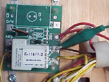
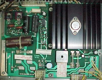
The 50 volt Coils.
On all system11 games, some coils such as the flippers and
the kick backs are high voltage 50 volt coils. On system11 and
system11A games (Fire! and before), to power
these coils a "50 volt power supply board" is used (the power supply board
itself does not supply this voltage). The 50v power supply board is a 6"x4"
skinny board on the far right side of the backbox. This board has an output voltage
fuse for the flippers, and an input voltage fuse mounted to the inside
of the backbox wood. Sometimes the 50 volt's bridge rectifier on this board dies.
If there is voltage at the AC lugs of the bridge, but no DC voltage on the position
and negative leads, the bridge has failed and gone open
(remember, the "offset" lug of the bridge
is the positive lug, and the negative lug is directly opposite). Bridges also
can short, which will cause the associated fuse to blow immediately.
On games before Big Guns (system11 and system11a), Williams used under-playfield
mounted 50 volt relays for the 50 volt coils. The TIP122 CPU board transistor
would momentarily energize the relay, which would in turn momentarily complete ground
to the 50 volt coil. This required a relay board to be mounted under
the playfield for each 50 volt coil. Williams stopped this with System11b (Big
Guns and later). Instead they used the Auxiliary Power Board, which had large eight TIP36
transistors to drive the 50 volt coils. The CPU board's TIP122 transistors
would pre-drive the Auxiliary Power Board's TIP36 transistors, which would
sink 50 volts and energize the 50 volt playfield coils (this means the TIP36
transistors became essentially solidstate 50 volt relays). The Auxiliary
Power Board (APB) also had eight fuses, one for each of the TIP36 transistors.
Hence the 50v power supply board is no longer used on system11B and
later games. The Auxiliary Power Board also
had a bridge rectifier for the 25 and 50 volts circuit. The APB board is
mounted directly below the power supply board on the right side of the
backbox.
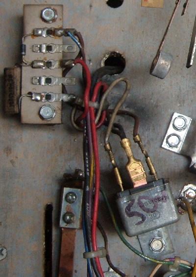
A 50 volt relay mounted under the playfield on High Speed for
the left side kickback. The diode for this relay is mounted on the
circuit board at the upper left.
|
The Bank Selected Solenoids and the A/C Relay.
On all System 11 games,
transistor Q7 or Q8 controls the "solenoid A/C select relay".
This is the relay that controls which bank (either "A" or "C") that TIP122 transistors Q22-Q25
and Q30-Q33 will control. This means one TIP122 transistor can control two different
devices (usually a flasher on bank C, and a solenoid on bank A). This
was called "multiplexing". Note
on System11 and System11A games before Big Guns (no Auxiliary power driver board), transistor
Q7 controls the solenoid A/C select relay. On System11B and System11C games Big Guns
and later (with an Auxiliary power driver board), then Q8 controls
the A/C relay mounted on the Auxiliary power driver board.
The solenoid A/C select relay is a 24 volt DC, 10 amp, DPDT relay (NTE R14-11D10-24P).
The location of the A/C relay is somewhat confusing. On High Speed and
Grand Lizard there is no A/C relay, as these two games do not use
system11's multiplexing feature. On F-14 Tomcat the A/C relay is mounted under
the playfield. Finding the A/C relay on system11A games can be challenging
because under the playfield can be a lot of relays! This happens because
prior to Big Guns all playfield 50 volt coils are activiated via a relay
board. The 50 volt and A/C relay board are identical looking. Just remember
on system11 and system11A the relay on the power supply is for the General
Illumination, and the relay on the CPU board is for the flippers. The remaining
playfield mounted relays are either a 50 volt coil relay or the A/C relay.
Also remember some System 11 games do not utilize the solenoid A/C select relay.
The first two system 11 games (High Speed and Grand Lizard) do not. There are
enough transistors on the CPU board so there is no need for any
transistors to be shared between two devices. In this case transistor
Q7 is used for a 50 volt kickback lane relay (on High Speed),
and the A/C select relay not used.
The A/C relay on a F-14 Tomcat (system11A), mounted on the bottom edge of the
playfield (center relay; the other two relays are 50 volt coil relays).
|
Test the Solenoid A/C Select Relay.
If the solenoid A/C select relay is not working correctly,
there will be strange game operation issues. A messed up
A/C relay, if stuck on bank "C", won't give any power
to coils 1 to 8.
If the relay is constantly energized (stuck on bank "C"),
it's probably because it's driver transistor (either Q7 or Q8)
is shorted. If it's stuck on bank "A" (where the relay
sits at rest) or won't energize, the flashlamps in the game won't work.
If the A/C relay won't energize, the game will fire coils when
its supposed to energize flash lamps! Or vice versa. This can give some
very strange game behavior.
If you are wondering what a particular relay does,
any individual relay can be activated quite easily. All relays should
have a 1N4004 diode associated with the relay. On playfield mounted
relays, this diode is mounted right next to the relay on the relay board. On the power
supply, CPU board, or Auxiliary Power Board the 1N4004 diode is right above the relay.
With the game in diagnostic mode, connect an alligator test clip to ground.
Touch the other end of the test clip to the NON-BANDED side of the relay's diode.
This will energize the relay. If the game is in solenoid test and is testing
one of the eight multiplexed solenoids, manually enerigizing the A/C relay
should switch the test from the solenoid to a flasher (assuming the game
is using a flasher for that multiplexed transistor). If it is a GI relay,
when the relay is energized the GI lights it controls should turn off.
If it is the flipper relay, energizing it should activate the flippers
via the cabinet flipper buttons (note the flipper relay will automatically
be energized when entering dianostic mode, so try this in attract mode).
The solenoid A/C select relay can also be tested via
its driving transistor. To do this, take your aligator test wire
and connect it to the metal tab on transistor Q7 (Fire! or
before) or Q8 (Big Guns or later). Then with the game on and
in attract or diagnostic mode, touch the other end of the
aligator clip to the ground strap in the backbox. You should
hear the A/C select relay click on and off. This will make
finding the relay a bit easier on system11 and system11A games.
If you don't hear the A/C relay "click", you should now test
transistor Q7/Q8. The quick and easy way to do this is:
- Turn the game off.
- Put your DMM on ohms (buzz tone).
- Put one lead on the ground strap in the backbox.
- Touch the other lead to the metal tab on transistor Q7/Q8.
- If you get zero ohms (buzz), the transistor is bad! (shorted on)
Is the Solenoid A/C Select Relay Bad?
Be aware that relays can go bad too. This can especially
happen if transistor Q7/Q8 locks on for some time, and leaves power to the
relay turned on. The relay can actually get so hot, it burns the
relay contacts together. Also, the solder joints on the A/C select
relay can go "cold" or fatique too. This often will make an A/C select relay not work
(but reflowing the relay solder joints can often fix this). If you need
to replace the A/C select relay, it's a 24 volt DC, 10 amp, DPDT relay.
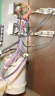
Turning on Relay A/C to test both coils/flashers that driver
transistors Q22-Q25 and Q30-Q33 control. Here transistor Q8's
metal tab is grounded with an alligator clip.
|
|
Special Solenoid Logic Flow.
For Special Solenoids (SSa to SSf), here is the logic flow. This
is useful to know if you are having a problem with a special
solenoid. I've had the Special Solenoid TIP/2n4401 transistor(s) lock on,
and back flow to kill its driving 7402 (this is quite common).
But it can go back one step further and kill the 7407 at U49 too
causing multiple other Special Solenoids to lock-on.
Luckily having a Special Solenoid kill its PIA is rare.
SSx:    6821 PIA    7407    7402   2N4401    TIP122
---------------------------------------------------
SSa:  U38 (pin 39) to U49  to U45  to Q74    to Q75
SSb:  U41 (pin 39) to U49  to U45  to Q70    to Q71
SSc:  U41 (pin 19) to U49  to U45  to Q72    to Q73
SSd:  U38 (pin 19) to U49  to U45  to Q68    to Q69
SSe:  U54 (pin 19) to U49  to U50  to Q76    to Q77
SSf:  U54 (pin 39) to U49  to U50  to Q78    to Q79
Since pre-Big Guns games use hardware logic to fire the solenoids (they
are not CPU controlled),
there are some other smaller (and easily damaged!) components
that can fail too. Check capacitors C70 to C75 (.01 mfd), and resistor
network SR20 (4.7k). If these become damaged, a special solenoid
can "stick on". Even if your game is Big Guns or later (CPU controlled
special solenoids), damage these components can cause problems.
Transistor Testing procedures, circuit board out of the game.
If you have a circuit board out of the game for some reason,
I would suggest testing all the solenoid/flasher driver transistors. It only
takes a moment, and will ultimately save you time.
To test a transistor, you'll need your
digital multi-meter (DMM) set to the "diode" position.
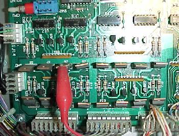
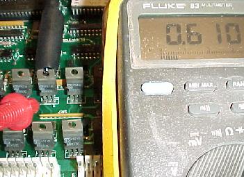
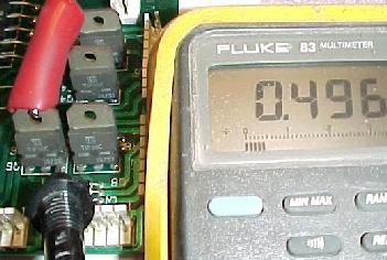
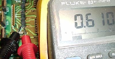
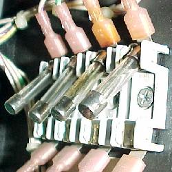
Testing a TIP122/102 transistor on the CPU board.
|
|
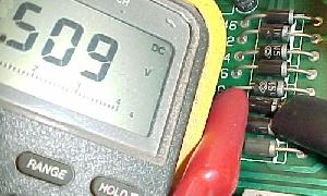
- TIP122/102: Put the black lead of your DMM on the center lead
or on the metal tab of the transistor. Put the red lead of your DMM on
each of the two outside legs of the transistor one at a time. You should get a reading
of .4 to .6 volts. Any other value, and the transistor is bad and will need
to be replaced.
Testing a TIP36c on the Auxiliary power driver board.
|
|
- TIP36c: Put the red lead of your DMM on the center lead
or on the metal tab of the transistor. Put the black lead of your DMM
on each of the two outside legs of the transistor one at a time. You should get a reading
of .4 to .6 volts. Any other value, and the transistor is bad and will need
to be replaced.
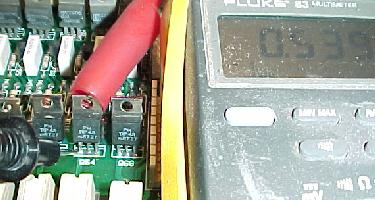
Testing a 2N4401 pre-driver on the CPU board.
|
|
- 2N4401 (pre-drivers): Put the red lead of your
DMM on the center lead of the transistor
(note this transistor doesn't have a metal tab).
Put the black lead of your DMM on each of the two outside
legs of the transistor one at a time. You should get a reading of .4 to .6 volts. Any other
value, and the transistor is bad and will need to be replaced.
Testing a TIP42 lamp matrix column driver transistor on the CPU board.
|
|
- TIP42: Put the black lead of the DMM on the base lead
(as facing the transistor, the left leg) of the transistor. Put the red lead of the
DMM on each of the two transistor legs (center and right), one at a time. The DMM should show
a reading of .4 to .6 volts. Any other value, and the transistor is bad and will need
to be replaced.
Most often transistors short when they go bad. This will usually
give a reading of zero or near zero, instead of .4 or .6 volts.
To enter diagnostics, the red center button must be
in the "down" position (as shown here). If the center
button is "up", you will enter the audits menu instead.
|
|
Testing Transistors/Coils, circuit boards installed in a (near) WORKING game,
using the Diagnostics Test.
If your game powers on, you can use the diagnostics to test most
devices. From the attract mode:
- Press the center red button inside the coin door to the "down" position.
- Press the black button closest to the coin door once.
- Press the center red button inside the coin door to the "up" position.
- Press the black button closest to the coin door to move
from test to test.
Solenoid Doesn't Work during Diagnostic Tests.
If a solenoid doesn't work from the diagnostic tests, here's what
to check. Turn the game off before doing this.
- Check all the fuses. A non-working
solenoid could be as easy to fix as just replacing a fuse.
- Find the solenoid in question under the playfield. Make
sure the wire hasn't fallen off or become cut from the coil
(a very common problem).
- If the above is correct, make sure the windings of the coil
haven't broken off from the solder lugs. If one has broken, you can
re-solder it. Make sure you sand the painted enamel insulation
from the wire before re-soldering.
- Check the coil diode. For games before Big Guns, the
coil diode will be right on the coil, with the banded side of the
diode connecting to the power side of the coil. For games with an
Auxiliary power driver board (Big Guns and later), the coil diodes
are mounted on the auxiliary power driver board
(flipper coils should always have diode(s) though, for all system 11 and WPC games).
Moving the diodes away from the coil increases reliability
as the diode is not subject to the jarring and heat a coil can
produce. It also eliminates the need for the operator to know which
coil wire goes to the banded side of the diode when replacing a coil!
A Coil doesn't Work, What To Do.
The following procedures will start at the coil, and work back
to the CPU board, testing components. This will eliminate things
and make finding the problem easier.
Testing for Power at the Coil.
Most pinball games (including system 11) have power at
each and every coil at all times. To activate
a coil, GROUND is turned on momentarily by the driving transistor
to complete the power path. Since only ground (and not power) is turned on and
off, the driving transistors have less stress on them. With this in
mind, if we artificially attach a coil to ground, it will fire
(assuming the game is turned on and in attract mode).
- Turn the game on and leave it in "attract" mode.
- Lift the playfield.
- Put your DMM on DC voltage (100 volts or greater).
- Attach the black lead of your DMM to the metal side rail.
- Touch the red lead of your DMM on either/both/all lugs of the coil in question.
- You should get a reading of 25 to 80 volts DC. Switch your red test
lead to the other lug of the coil, and you should get the same voltage again.
On flipper coils, test all the lugs of the coil for power.
If you don't get any voltage reading, no power is getting to the coil.
If you don't get power at all lugs, then you have a broken
winding on the coil itself. Replace the coil or fix it (if the winding
is an outside winding, you can remove the paper label and unwrap a turn
of wire, sand the insulation off, and resolder the coil winding to the lug).
- If no power is getting to the coil at any lug, it may be a coil that is
A/C relay selected. Push the center red coin door button down,
and press the black button closest to the coin door. This will
put the game in diagnostics mode. This should
de-energize the solenoid A/C relay, and turn the power to the coil
in question on. If there is still no power, put an aligator clip
on the metal tab of transistor Q7 (Fire! and before) or Q8 (Big Guns
or later) to activate the solenoid A/C relay, and retest for power
at the coil again.
- A broken solenoid A/C relay can cause power to not get
to a coil. But this will affect more than one coil. Cold solder
joints on the A/C relay-to-board solder pads can do this too.
- If no power is getting to the coil, a wire is may be
broken somewhere. Trace the power wire. Remember, the power wires
are "daisy-chained" together. So if there is a break in the wire
at a previous coil, the coils down stream will not get power.
Coil Test to Make sure Coil is Good.
Here's another method of testing coils, which is more "low-level".
This will test if the coil itself is good, and that there is power
at the coil.
- Game is on and in "attract" mode, and the playfield lifted.
- Connect an alligator clip to the metal side rail of the game.
- Momentarily touch the other end of the alligator clip to the GROUND lead of the coil
in question. This will be the coil lug with the single (thinner) wire attached.
On coils with a diode, the ground coil lug is the one with the non-banded side of the
diode connected. On FL11630 flipper coils F-14 Tomcat and later, touch the middle lug to ground.
- The coil should fire (if you accidentally touch the alligator clip
to the power side of the coil, the game will reset and/or blow a fuse,
as you are shorting solenoid high voltage directly to ground).
- If the coil does not fire, it may be a coil that is
A/C relay selected. Push the center red coin door button down,
and press the black button closest to the coin door. This will
put the game in diagnostics mode. This should
de-energize the solenoid A/C relay, and turn the power to the coil
in question on.
- If the coil still does not fire, either the coil itself is bad,
or the coil's fuse is blown and power to the coil is not present.
Testing the under-the-playfield Relay Board.
On most system 11 games, there are a mix of some 50 volt
and 25 volt coils. For games without Auxiliary power driver boards,
most games use relay boards to power the 50 volt coils. A TIP122/102
transistor on the CPU board energizes the under the playfield
relay board. This relay then turns on the ground to the 50 volt
coil, motor or other device. This was done because the original TIP122 on the CPU
board can't handle the current draw of a 50 volt coils or motors.
The under the playfield relay boards were no longer required on 50 volt coils
with games that had an Auxiliary power driver board (APDB). That's
because the APDB had TIP36c transistors to control the
50 volt coils, replacing the need for the small relay boards.
But some games even with the APDB still used
under the playfield relay boards for other uses (like turning off
specific strings of GI lights, like on Big Guns).
Under-the-playfield relay boards were still used after the introduction
of the Auxiliary power driver board. Their function was to turn sections
of the playfield GI lamps off.
|
|
It is easy to test the under the playfield relay boards.
Connect an alligator clip wire to the "DRV" lead on the small
relay board. Connect the other end of the alligator clip
to ground (the game's metal side rail). This will energize the relay (you should hear a
"click"), and the device it powers should also operate (or possibly
turn off a section of GI lights).
Cracked Solder Joints on the 50 Volt Coil Relay Boards.
On system11 games before Big Guns (those games without the Auxiliary
Power Driver board), Williams used small relay boards under the playfield
to drive the 50 volt coils. Since the games were really set up for
28 volts coils, a 28 volt relay was driven by the driver board TIP122/102
transistor, and hence the relay would turn on the 50 volt power to the
desired coil. This was only on games before Big Guns, as the Auxiliary
Power Driver board utilized eight TIP36c transistors which could handle the
50 volt coils without using a relay board.
On the games using relay boards for the 50 volt coils,
often the solder joints on the under the playfield relay boards
are cracked or "cold". If you are having a problem with any device
that is controlled by a relay board, re-solder all the header pin solder points
on the relay board. Also the 150 ohm resistor used on the relay board
can burn and go open.
Locked On 50 Volt Coil, Sys11/Sys11A.
If a system11 and system11a game (Fire! and before) have
a 50 volt coil is locked on at game power-on, this is
usually a under-playfield mounted relay board problem.
The CPU board TIP122 turns the 28 volt relay board's relay on.
This in turns completes the 50 volt power path to the coil
through the relay switches.
If the 1N4004 diode on the 50 volt coil fails, the relay
switches for this relay will take extreme abuse (big huge
blue spark). Eventually this will burn the switch contacts
to the point where they weld together. And this will cause
the 50 volt coil to lock-on at game power on.
To fix this problem first make sure the coil's 1N4004 diode
is not broken or shorted. Then look at the associated relay
on the relay board. You will have to remove the plastic cover
from the relay, which should pry off. Examine the switches
on the relay, and adjust/clean as needed. To clean these
relay switches, use a Flexstone file (this unlike cleaning
the gold contact playfield switches, which should *never* be
filed). Also make sure the 150 ohm resistor on the relay board
is not burnt. When done, push the plastic cover back on the relay
(it should snap in place).
To test the relay and the 50 volt coil it powers, use the game's
diagnostics. Or ground the non-banded side of the 1N4004
diode on the relay board (which complete 28 volts power to the relay board).
This will energize the relay, which
in turns energizes the 50 volt coil. Note there are two 1N4004
diodes on the relay board. The one you want to ground is the non-banded side of the
1N4004 diode that is by itself (*not* next to the 150 ohm resistor).
Grounding the "DRV" lead with an alligator clip on the under
the playfield relay board to energized the device this board
controls.
|
|
Testing TIP122/102 Transistor and Down-Stream Wiring/Coil.
If the coil fires in the above test, you may have a transistor problem.
You can also test the everything from the TIP122/102 downstream to
the coil itself (but note this does not test the transistor itself).
Only do this for the TIP122 or TIP102 transistors! Damage can occur if this
test is done on other transistors (like TIP42 or TIP36). This test
will test everything from the CPU board's TIP122/102 down to the coil itself. If
this test passes, and your coil still doesn't
work in game play, you have a problem more "up stream". All that is
left is the TIP122/102, the 2N4401 pre-driver transistor, the logic TTL chip
that ultimately controls the whole process (a 7402 for the special
solenoids or 7408 for the standard solenoids), and possibly the driving PIA 6821 chip.
- Game is on, and in diagnostic mode (push the center red coin door button down,
and press the black button closest to the coin door; this will
put the game in diagnostics mode).
- Remove the backglass.
- Find the transistor that controls the coil and/or flasher in question
(refer to the manual).
- Attach an alligator clip to the grounding strap in the bottom
of the backbox.
- Momentarily touch the other lead of the alligator clip to the metal
tab on the TIP122/102 transistor (only works on these).
- The coil or flasher should fire.
- If the coil or flasher does not fire, it may be a transistor that is multiplexed
through the solenoid A/C relay.
- To energized the solenoid A/C relay (which will fire the other coil/flasher
that is multiplexed), attach an alligator clip to the grounding strap in the
backbox. For games prior to Big Guns (no Auxiliary power driver board), connect
the other end of the alligator clip to the metal tab of transistor Q7. For
games Big Guns and later (with an Auxiliary power driver board), connect
the other end of the alligator clip to the metal tab of transistor Q8. This will
energize the solenoid A/C relay on the power supply or the Auxiliary power driver board.
- If the coil or flasher does not fire, and the coil or flasher
did fire in the previous test, you probably have a wiring problem.
A broken wire or bad connection at the connector would be most common.
It is also possible you have a bad driver or pre-driver transistor. Use your meter
and test the transistors on the board (see
Transistors Testing Procedures for details).
I've Done the Above Tests & they Work, but the Coil still doesn't
work in Game mode.
You have preformed all the above tests and replaced/tested the coil, TIP36c, TIP122/102
and/or the 2N4401 transistors. But the coil still doesn't work in game mode!
If the coil in question is a special solenoid (pop bumpers, slingshots),
you need to look at the driving components.
There are some other smaller (and easily damaged!) components
that can fail too for the special solenoids.
Check capacitors C70 to C75 (.01 mfd), and resistor
network SR20 (4.7k). If these become damaged, a special solenoid
can "stick on". Even if your game is Big Guns or later (CPU controlled
special solenoids), damage to these components can cause special solenoid problems.
There are more components that needs to be tested or replaced too,
if the transistors themselves are good. This is the hardware
logic chips that drive the pair of TIP102/2N4401 transistors:
- Q2/Q6, Q3/Q7, Q10/Q14, Q11/Q15: 7408 at U17, 6810 PIA at Uxx.
- Q4/Q8, Q5/Q9, Q12/Q16, Q13/Q17: 7408 at U18, 6810 PIA at Uxx.
- Q18/Q22, Q19/Q23, Q26/Q30, Q27/Q31: 7408 at U19, 74LS374 at U28, 6810 PIA at U54 or U38.
- Q20/Q24, Q21/Q25, Q28/Q32, Q29/Q33: 7408 at U20, 74LS374 at U28, 6810 PIA at U54 or U38.
- Q68/Q69, Q70/Q71, Q72/Q73, Q74/Q75: 7402 at U45 (special solenoids).
- Q76/77, Q78/Q79: 7402 at U50 (special solenoids).
- Q80, Q81, Q82 TIP122/102 lamp row drivers: 7406 at U55, 6810 PIA at U54.
- Q83, Q84, Q85, Q86, Q87 TIP122/102 lamp row drivers: 7406 at U56, 6810 PIA at U54.
Turning on Relay A/C to test both coils/flashers that driver
transistors Q22-Q25 and Q30-Q33 control. On Big Guns and later,
transistor Q8's metal tab is grounded with an alligator clip.
On pre-Big Guns (games with no Auxiliary power driver board),
transistor Q7's metal tab is grounded instead.
| |
|
Installing a New Transistor.
If you have determined a coil's transistor is bad,
there are a few things to keep in mind. Most TIP122/102 transistors
also have a "pre-driver" transistor (2N4401 or NTE123AP).
If you replace a coil's TIP122/102 transistor, it's a good idea to also replace
its corresponding pre-driver. It will be located near the TIP transistor.
See the schematics to determine
the specific pre-driver transistor(s).
Game with an Auxiliary power driver board (Big Guns and later),
use a bigger TIP36c driver transistor for high voltage devices. These
TIP36c transistors have TWO pre-drivers: a TIP122/102 and a 2N4401
transistor. Again, if the TIP36c has failed, it's a good
idea to replace both corresponding pre-driver transistors.
Replacing the pre-driver transistors is optional (if they test
Ok). You can always test these pre-drivers instead of just
replacing them. But if the driver transistor has failed, the
pre-driver was probably over-stressed too.
It is a good idea to replace the pre-driver transistor(s) too.
Replace TIP122 transistors with TIP102?
This is a very common question. The TIP102 is a more "hardy" transistor
than the TIP122, but works exactly the same. So why not replace a bad
TIP122 with a TIP102? Well, actually I recommend the TIP102 over the TIP122.
Some people may argue with this, claiming the TIP102 will not go bad as quickly,
and therefore can cause more heat and damage the circuit board before or
while it fails. But if the transistor is already shorted, it really doesn't
matter if it's a TIP122 or TIP102. It's still shorted, and will
still cause the same heat and damage. So my recommendation is to
replace all bad TIP122 transistors with the more robust TIP102.
After all, this is what Williams started using on their next generation
of pinball boards (WPC) after system 11. The TIP102 if far more robust
than the TIP122 (which frankly was barely robust enough for the given job).
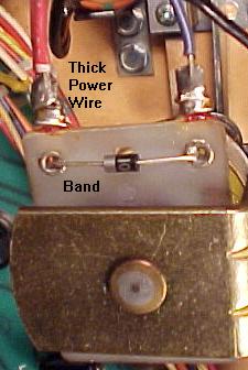
The diode mounted right on the coil,
games Fire! and before. Note the thicker
red power wire on the left goes to the
banded side of the diode. The thinner
wire on the right lug goes to ground.
|
|
Coil Diodes.
On all electronic pinball games, each and every CPU controlled
coil must have a coil diode.
This diode is VERY important. When a coil is energized, it
produces a magnetic field. As the coil's magnetic field
collapses (when the power shuts off to the coil),
a surge of power as much as twice the energizing voltage
spikes backwards through the coil. The coil diode prevents
this surge from going back to the circuit board and damaging components,
or causing the CPU to get confused (which often results in a game
reboot).
If the coil diode is bad or missing, it can cause several problems.
If the diode is shorted on, coil fuse(s) will blow. If the diode
is open or missing, strange game play will result (because
the CPU board is trying to absorb the return voltage
from the coil's magnetic field collapsing). At worst a missing
or open diode can cause the driver transistor or other
components to fail.
When Replacing a Coil Diode...
Remember to always install a coil diode with the banded end
of the diode to the power wire coil lug! The power lug is the the one
with the thicker red or purple wire connected to it.
This is usually the lug with TWO wires connected to it (because
the power wires "daisy chain" from coil to coil). If you install
a diode in reverse, it will instantly short and be ruined when power is applied.
Diodes Mounted on the Coil.
Sometimes a diode lead breaks on the coil
from vibration. When replacing a coil, the repair person
can install the coil wires incorrectly (the power wire should always be
attached to the coil's lug with the banded side of the diode).
To prevent this, Williams moved the coil diodes off the coils
and onto the Auxiliary power driver board starting with Big Guns.
This isolates the coil diode from vibration and
eliminates the possibility of installing the coil's wires in reverse.
This was done on most coils except the flipper coils.
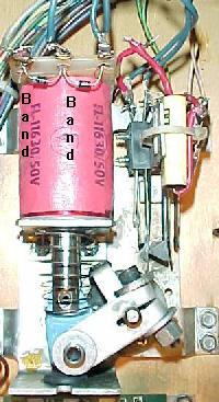
The coil diodes on a FL11630 flipper coil, F-14 Tomcat and later.
Note the solo center blue wire and the blue wire on the right lug
goes to the EOS switch. The left lug (or gray/yellow) is the "hot" wire.
The second blue/violet wire on the right lug continues to the cabinet
switch and ultimately ground. Note the orientation of the diode bands.
|
|
Testing Diodes on the Auxiliary power driver board.
If you suspect a problem with a coil diode (game resets during
multi-ball when lots of coils are firing), you can test the
coils on the Auxiliary power driver board. Just set your DMM
to "diode" setting, and put the black lead on the banded side
of the diode, and the red lead on the non-banded side. You should
get a reading of .4 to .6 volts. If you reverse the leads, you
should get a null (no) reading.
Testing a coil diode on the Auxiliary power driver board.
|
|
Test a Diode on a Coil?
You can test coil diodes. They do fail and they do break. This is true mostly for just
the coil diodes that are actually mounted on the coil itself. Testing
coil diodes is somewhat a waste of time. If you suspect a coil diode is
bad, just cut the old one off and solder on a new one. They are so inexpensive,
it's not really worth trying to test them. Most bad coil diodes are physically
broken, and you can usually see the damage.
But if you want to test a coil diode, you can.
If the coil diode is mounted on the coil,
you will need to clip one end of the diode off the coil lug to
test it (that's why just replacing the diode is a good idea if
you suspect a problem). If you game has an Auxiliary power driver
board (Big Guns or later), the coil diodes are mounted on the Auxiliary
power driver board. These rarely go bad.
Use your DMM set to "diode" setting, and test the board
mounted coil diode. With the black lead on the banded side of the
diode and the red lead on the non-banded side, you
should get between .4 and .6 volts. Reverse the
leads (red lead to banded side of diode), and you should get
a null reading. If you don't get this reading, cut one lead
of the diode from the circuit board, and repeat the test.
If you still don't get these results, replace the diode with
a new 1N4004 diode.
Test the Coil Resistance with a DMM.
After replacing the driver transistor, ALWAYS measure the resistance
of the associated coil. This is important.
If a coil gets hot (becuase its driver transistor was shorted),
it can burn the painted
enamel insulation off the coil windings. This lowers the overall resistance
of the coil because adjacent windings short together.
If resistance gets much below about 2.8 ohms, the coil becomes
a "short", and will fry its associated driver transistors very quickly!
To test the coil's resistance, it is best to remove the attached wire
from one (either one) of the coil's lugs. Then set the DMM to low
resistance, and put the DMM leads on the lugs of the coil. Most coils should
be in the 5 to 15 ohm range, but could go as high as 150 ohms, or as low
as 2.5 ohms. If the coil is below that, it should be replaced with
a new coil of the same type. Coils with resistance below 2.5 ohms are
basically a dead short, and this will fry its associated driver transistor.
Installing a New Coil.
Many replacement coils will come with a diode soldered across
its solder lugs. On System 11 games Big Guns and after, all coils except the flipper
coils have the diode mounted on the Auxiliary power driver board.
For these coils you can cut the diode off the coil before installing. You can
then solder the coil wires to either coil lug. You
can leave the diode in place, but you must install the
coil wires correctly. Though you still have the circuit board mounted diode as protection,
you could damage the coil's driver transistor.
For games Fire! and before (with no Auxiliary power driver board),
the coil's ground wire (usually the smaller wire) MUST go to the
lug of the coil with the non-banded side of the diode. The power wire
connects to the lug with the banded side of the diode. If you have
the wires reversed, this essentially causes a shorted diode,
which destroys the diode.
Coil Doesn't Work Check List.
If a coil doesn't work in a game, here's a check list to
help determine the problem.
Before you start, is the coil stuck on? (Hint: is there heat, smoke and a bad
smell?). If so, the coil's driving transistor has probably failed.
Turn the game off and check the driving
transistor, and replace if needed. See Transistors
Testing Procedures for more info.
If the coil just doesn't work, here's a list of things to check:
- Have the power wires fallen off the coil's solder lugs?
- Is the coil damaged? Has the internal winding broken off the
coil's solder lug?
- Is there power at the coil? See Testing for
Power at the Coil for more details.
- If there is no power at the coil, check its fuse.
Always remove the fuse from the fuse holder, and check the
fuse with a DMM set to ohms.
- Check the other coils that share one of the same wire colors.
Are they working too? If not, suspect the fuse that handles these coils.
- Power to coils are often ganged together. If the power wire
for this coil has fallen off a previous coil in the link, power may not get
to this coil.
- Using your DMM and its continuity test, make sure the coil
connects to the correct connector/pins on the CPU board.
- With the game on, ground the non-banded diode side of the coil,
to see if the coil works.
- Check the driving transistor. Usually this transistor will short on
when it fails, but not always.
- With the game on, momentarily ground any of the 28 volt coil's associated
TIP122/102 driver transistor's metal tab. The coil should energize. This checks the wiring
from the driver board to the playfield coil.
End of System 11 Repair document Part One.
* Go to System 11 Repair document Part Two
* Go to System 11 Repair document Part Three
* Go to the Pin Fix-It Index at http://pinrepair.com
|

