3c. When thing don't work: Game Resets/Boot-Up Problems, and Immediate Blowing Fuses.
Random Game Resets and Lock-Ups.
A very common problem with System 11 games is random game resets and lock ups. This can happen
any time, but seems most prevalent during hard game play (like multiball). The game
just locks up, no scoring, displays are frozen, lamps locked in their last state.
Or the game resets, seemingly turning itself off and back on.
This generally happens during game play because all the coils are firing, putting stress on the
power supply. Supplying all this high current to the coils can cause a marginal
power supply to sag. If the regulated +5 volts drops below about 4.8 volts DC even
for a micro-second, the game can reset or lock up. Or if a coil's EMF spikes back
to the CPU board, a lock up or reset can occur (more on this below).
Broken Coil Diodes Cause Game Resets and Strange Behavior.
The most common cause of the reset/lock up problem is a broken diode on the flipper coil(s).
If a diode breaks (or fails) on a coil, this allows a demagnetizing spike to
go back to the CPU board. As a DC coil magnetic field collapses when it is de-energized, it creates
an electrical spike many times higher than the voltage supplied
to energize the coil. This EMF (Electro-Motive Force) travels backwards
through the circuit, and can freak-out or even damage the CPU board.
The purpose of the coil diode(s) is to
stop this EMF spike from going back to the CPU. But the constant jarring of a
coil can cause the diode or its solder joint to break or crack.
Because of this, starting with "Big Guns",
all coil diodes (except the flipper diodes)
were moved to the Auxiliary power driver board to isolate them from coil vibration.
But games "Fire!" and prior have the diodes mounted right on each coil.
Other popular coils to break their diodes are the pop bumpers and slingshot
coils. These coils get lots of action, and can easily break their
diodes (on games "Fire!" and before).
If one of these coil diodes fails it can also damage the CPU board, inparticular that
coil's driving TIP122/TIP102 transistor and even the logic circuit that
drives it.
The best solution is just to replace every flipper coil
diode. These 1N4004 diodes are very cheap and easy to replace. It only
takes a few minutes to cut the old ones off and replace them with new
1N4004 (or 1N4007) diodes. Testing these diodes really is a waste of
time, as they are so cheap (and can often test as good when they are
really bad). As for the other coils (pop bumpers, etc.)
and their diodes, just do a general
inspection to make sure they are installed and not cracked. A gentle tug
on the diode with the fingers is all that is needed to see if a
coil diode is cracked.
Other Things That Cause System11 Game Resets.
If the flipper and other coil diodes are Ok,
here' a list of other things to check on system11 games with reset/lock up problems:
- Inspect every coil diode for cracks or loose/broken leads,
especially the flipper coils.
- Put the game in diagnostic switch test, and press all the playfield
switches. Make sure no one switch activates two
switches (or more) on the score display during this test (indicating a switch matrix
problem, which can slam tilt a game into a reset).
- Check the +5 volts on the CPU board with the game in attract
mode. Should be 4.9 volts to 5.2 volts DC. If it is not in this
range, there is a power supply problem (even if the voltage is in
this range, there can still be a power supply problem!)
- Check the input (wall) voltage to the game. It should be in the
115 to 125 volt AC range. If it is below 115 volts, resets can occur.
- Check the power supply fuse holders F5 and F6. Sometimes these
can tarnish or crack, or the fuses themselves can become resistive.
- Replace the +5 volt filter capacitor C10 (18,000 mfd, 20 volts)
on the power supply. These games are 15+ years old, and these
filter capacitors have an approximate lifespan of about 10 years.
So every system11 game is really due to have this capacitor replaced!
- Replace the power supply capacitor at C8 (47 mfd, 50 volt).
This cap often goes open and will cause a low +5 volts.
- If the +5 volts is still low or the game is still resetting,
replace the power supply bridge rectifier BR1. This is a 35 amp 200 volt
lug lead bridge.
- If the +5 volts is still low or the game is still resetting,
replace the +5 volt Darlington transistor on the power supply at Q5 (2N6057, but
replace with a 2N6059).
- If the +5 volts is still low or the game is still resetting,
replace the +5 volt regulator chip on the power supply at IC1 (MC1723C,
also known as a 723C).
- If the game is still resetting, look for
cracked solder joints on the backs of the connector pins on all of
the boards in backbox. This is a common problem and can cause reset
as well. The most likely connectors to cause reset problems are power supply
connector 3J6 (power out) and CPU connectors 1J17 (power in).
Resoldering these circuit board connectors.
The Diode's Band: Install them Right.
Remember when replacing coil diodes you MUST install the new diode
with the band in the same direction as the removed diode (though this isn't always
a good thing to assume!).
The diode's band is always connected to the power lug of
a coil. This is usually the lug with the red or purple, thick
wires going to it (there is often two power wires, because power is
"daisy chained" from coil to coil). If a diode is installed in reverse, that is the equivalent
to having no diode installed! The reversed diode will immediately
short and be ruined when power is applied.
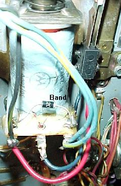
Note that diode installation is slightly more complicated
to figure out on three lug flipper coils. See the below picture for
a reference. But on two lug coils, the power lug is usually the thicker
of the two wires. Always check the schematics if you are not sure.
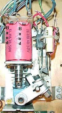
Left: The coil diodes on a FL11630 flipper coil, F-14 Tomcat and later games.
Note the solo center blue wire and the blue wire on the right lug goes to the
EOS switch. The left lug (or gray/yellow) is the "hot" wire. The second
blue/violet wire on the right lug continues to the cabinet switch and ultimately
ground. Notice the orientation of the diode bands.
Right: The diode on a series wound FL23/600-30/2600 flipper coil. Notice the
two wire on the right lug. These are the power wires. There are two because
the power "daisy chains" to the next coil down the line. These power wires
connect to the BAND side of the diode. The EOS switch connects to the far left
lug (the ground connection), and the middle lug. The far left lug is the "thick
coil winding wire" lug.
|
|
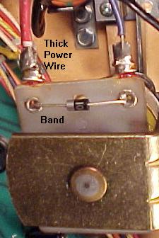
The coil diode on a regular two lug coil.
Notice the band goes to the power
(thick wires) side of the coil. Games Fire!
and before have diodes mounted
right on all the coils. After Fire!,
the diodes are moved to the Auxiliary
power driver board.
|
|
Game Just Won't Power On Consistently.
System 11 games can develop a problem with the POR (Power On Reset) circuit.
If this circuit isn't working correctly, ofen you won't get the
CPU to boot-up consistently, or at all. This can
mean a "7", "8" or blank in the LED diagnostics box (system 11) or 7 or 8 LED flashes
system 11a, b, c).
One thing that can cause the POR circuit to no operate is out of
spec +5 volts. This can be caused by a bad +5 volt bridge or filter capacitor.
The easiest thing to do is to isolate the power supply from the CPU board.
To do this, remove the CPU board from the backbox. Then power the CPU board
from an external power supply (as described below). If the problem still
exists (inconsistent CPU booting), the problem is on the CPU board itself.
To "go around" the POR section of the board, you can do a simple test.
After attempting to boot the CPU board, ground the /RESET line on the
CPU chip (pin 40 of U15) momentarily with
a test clip. If the board boots up consistently
without a problem (correct flashes or "0" in the LED),
then the POR section is definately at fault.
The POR section's job is to look at the +5 and +12 volts, and make sure
they have stablized, as determined by zener diodes ZR1 (1N5996A, 6.8 volts .5 watt) and
ZR2 (1N5990, 3.9 volts .5 watt) before
starting the CPU. This is done by transistors Q34, Q36 and Q38, but
before these three transistors can work, capacitor C30 and resistors
R55 and R56 provide a delay to allow the voltage to stabilize. Only
then the /RESET line can be released.
Any of these POR components could be bad, and not causing the
CPU board to boot properly. If the board boots inconsistently,
first look at capacitor C30 (a 22 mfd 10 volt electrolytic). If you don't have
any way to test the capacitor, just clip another 22 mfd electrolytic
cap across the leads of the existing C30 cap (positive to positive, negative
to negative, a parallel connection). If the board now boots up
consistently, you have found your problem! If not, check resistors
R55 (4.7k 1/4 watt) and R56 (10 ohm 1/4 watt),
and transistors Q34, Q36, Q38 (2N4401).
Bridges in System 11 Games.
Bridge failure is a much less common occurrence on system 11 games than
on Williams' newer WPC games. But it does happen. Usually when the BR1 +5
volt power supply bridge
fails, fuse F5 or F6 (7 amp slo-blo) on the power supply blows. If you replace this
blown fuse, turn the game back on and the fuse immediately blows; this
means the +5 volt bridge BR1 on the power supply board is shorted
and must be replaced.
Be aware that bridges which are circuit board mounted have wire
legs. Bridges that are screwed to the back of the backbox have
lug style legs.
Here are a list of the bridges and their associated filter capacitors:
- BR1 on Power supply board: +5 logic volts, through C10 (18,000 mfd 20 volts).
After filtering, goes to a voltage regulator and to Q5 (2N6057) with a
large heat sink. Just before the bridge are fuses F5 and F6. If either
fuse blows immediately upon powering the game on, bridge BR1 on the power
supply board has failed.
- BR1 on Auxiliary power driver board (Big Guns and later):
+25 volt solenoid power, through
C3 (100 mfd 100 volts), and to the solenoid A/C select relay.
On games Fire! and before, this bridge is mounted to the back
of the backbox (not on a board).
- BR2 on Auxiliary power driver board (Big Guns and later):
+50 volt solenoid power, through
C1 (100 mfd 100 volts), and to the solenoid A/C select relay.
On games Fire! and before, this bridge is mounted to the back
of the backbox (not on a board).
- 6BR1 (lower right corner of backbox): +18 volts for the lamp matrix, through
a 30,000 mfd 25 volt filter capacitor (mounted next to the bridge).
- BR1 on the Flipper power supply board (Fire! and before): flipper
+50 volts, through C1 (100 mfd 100 volts).
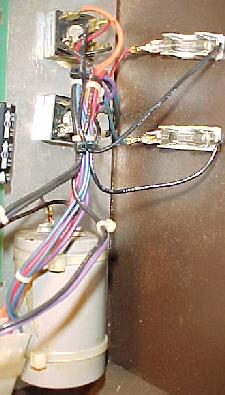
The +25 volt solenoid power bridge and
+18 volt lamp matrix power bridge, and its
large 30,000 mfd cap. These components
don't fail often. Note the two fuses added
on the right. Games prior to Fire! need these
fuses added to the solenoid and lamp matrix
bridges on the left. If a bridge or cap shorts,
a fire could occur without these fuses.
|
|
When Replacing BR1 on the Power Supply Board, Replace C10 too.
Capacitor C10 on the power supply board is a 18,000 mfd 20 volt filter cap. Its job is to
make the +5 volts smooth. This cap is fed from the bridge rectifier BR1
on the power supply board. If this bridge has failed, you should also
suspect its associated capacitor C10 to be bad (or close to bad) too.
These two components work together, and both need to be in good shape
to have nice smooth +5 volt logic for all the circuits in the game.
Capacitors are largely a mechanical device, and they do wear out.
Expect a 10 year life from a filter capacitor. That means replacing
C10 is a good idea anyway (because all system 11 games are at least 10 years
old now). A good C10 capacitor will also put less stress on all the +5 volt
logic circuits.
"IRQ Failure" Error Message at Power-on.
This message is often seen when the +5 volts is too low.
Check the +5 volts, should be in the 4.9 to 5.1 volt DC range.
3d. When thing don't work: Power Supply Issues.
The power supply on system11 games uses a 2n6057 (or 2n6059) as the
voltage regulator. It also has a support chip MC1723 to aid in the
voltage regulation. THis isn't as slick or nice as say the Bally
system (which uses an LM323 and has far less parts to fail), but
hey it's what Williams felt was right at the time.
Note that system11 used two different flavors of power supplies.
High Speed to Swords of Fury (pre-Taxi) used the same D-8345 power supply
as System9 games (with a slight modification to the GI power supply connectors).
This power supply output -12, +12, +5, -100, +100. In addition +18 (lamp matrix)
and +25 (coils) power is turned around through the power supply to inplement fuses
(though it's not rectified by the power supply). A separte small "flipper"
power supply board rectifies/outputs 50 volts for high power coils.
When the Auxiliary Power Supply board was introduced with Big Guns, the D-8345
power supply was not fully populated, as the GI, lamp matrix, and coil fuses
and related connectors were deleted from the design. They did this in steps.
For Big Guns the lamp matrix and 25 volt
coil connectors were removed, as were these associated fuses, but the GI connectors
were still present. By Banzai Run, the GI relay/connnectors were gone, and the
D-8345 power supply only had three fuses (one for high voltage, two for the 5/12
volt bridge rectifier). This under populated D-8345 power supply was used on Big Guns,
Space Station, Cyclone, Banzai Run, Swords of Fury). The lower section with the
GI connectors (on the lower right) was left blank (no GI relay or GI connectors).
Also the 18 volt lamp matrix connector/fuse was removed, as was the 25 volt
low-power solenoid connector/fuse.
With Taxi Williams changed to a physically smaller power supply board #D-12246 that outputed
-12, +12, +5, -100 and +100 volts DC and had just three .156" Molex connectors
(no longer was the rectangle 12 pin input connector used). This was done so the
new power supply could not be used in pre-Taxi games. All other voltages (18 volts
lamp matrix, 25 volt low-power coils, 50 volt high power coils, GI) was generated and
fused by the Auxiliary power supply board (or inter-connector board in the case of GI).
So the physically size of this new power supply was much smaller.
What about the circuits on the two power supplies? Effectively they are the same.
Just a different footprint and layout. So the information below about repairing
a power supply applies to both designs.
The Three Small Cap Kings and the Big Boy.
Note this information and parts designations applies to
both system11 power supply designs.
Because there's a large heat sink for the 2n6057 voltage regulator, anything
close to it can be tormented by heat. This can be a problem for three small
(but important) capacitors. They are 100 mfd (c7), 47 mfd (c8), and 330 mfd (c12). I highly
suggest changing these three caps if you have the power supply out for any
reason. It's like $1 worth of parts, and will save you quite a bit of potential
trouble down the road.
The 100 mfd cap at c7 is really important, as it's not a filter
cap (not tied to ground). Instead it's inline with the fuse, and if it fails,
the entire +5 volt rail will go low and perhaps to nearly 0 volts. The other
two small caps are filters to ground, and if they go bad, it's less of a
problem. But again all these are close to the large heat sink, and can
get cooked. Worse case is they physically leak, which is corrosive (like
a battery), and can cause other mayhem. I've seen these leak and corrode
the board, and even short the high voltage section of the power supply!
In addition there's a single large 18,000 mfd capacitor at c10. This is used to
filter the raw 12 volts before it's rectified to +5 volts. Examine the
cap and look for buldging at the ends. This is a sign of a bad capacitor.
If you see this, replace this cap.
Low +5 volts from the Power Supply board.
Note this information and parts designations applies to
both system11 power supply designs.
A low +5 volts (below 4.9 volts DC) coming from the power supply
can often be attributed to the c7 100 mfd 25 volt cap and the
c8 47 mfd 50 volt capacitor. If these
caps fail (opens up), a low +5 volts will result. A low +5 volts can cause
your game to reset randomly. Note you can replace the 47 mfd C8 cap
with a 100 mfd version.
Also a bad capacitor at C10 (18,000 mfd 20 volts)
can cause a low +5 volts. This cap is the main +5/12 volt filter cap. To test
this cap, turn the game on and put your DMM on AC volts. Put the leads of your
meter on the positive and negative leads of the C10 capacitor. If you get
more than .3 AC volts, replace this capacitor. Filter caps don't last forever.
Expect about 10 to 20 years life from them (which means most system 11 games
are on the short side of that curve). But when in doubt, just replace
C10 as it's probably due to be replaced anyway.
Lastly, resistor R7 (1/4 watt 2.15k ohms, either s11 power supply design)
can be manipulated to get
a greater 5 volt output from the 2n6057 regulator. For example, changing
this resistor from 2.15k ohms to 2k, can change the regulator output
from say 5.04 volts to 5.16 volts (that's the latest example where
I did this modification.) Using a 1.8k resistor will get about 5.25 volts.
Note this works on early System7 and System9 power supplies,
and early Dataeast power supplies
too (but the resistor designation is R2 on Dataeast.)
Low +12 volts from the Power Supply board.
If your +12 volts is low (below 10.5 volts), check/replace the large
power transistor 2N6057 on the power supply board.
Sometimes the socket used to connect this transistor is
corroded or simply not making good contact.
3e. When thing don't work: Power-On Tones and Sound Diagnostics/Problems
"System 11 sound used 'FM sound', which is
generated from the YM2151 8-voice FM synthesizer chip. Digital sound data from
the YM2151 is converted into an analog signal in the YM3012 DAC chip. A preamp
MC1458 chip pre-amplifies this analog signal before it is sent to the mixer and final amplifier.
System11 usually assigned a pair of FM-voices for an instrument. This is what made
system11 FM-synthesis stand out in sound quality and innovation.
The synthesizer was also capable of making noise sounds and this was used for most of the
cymbal and hi-hat sounds.
Williams used the term 'general sound' for any sound created by the MC1408 DAC chip.
Sampled sounds, such as drums, are processed through the DAC. These are all 8-bit samples
stored in ROM.
Algorithm-based sounds are also processed through the DAC. These sounds are created by
software algorithms. They are played monophonically (only one sound can play at one time), and are
easily distinguished this way. Algorithm-based sound was used widely in Williams system 3
through 11B games, and it was stopped starting with system 11C games.
All speech is generated from the 55536 CVSD chip. Digital speech data is clocked serially
into the CVSD chip and converted into an analog signal. A preamp chip (MC1458) pre-amplifies
this analog signal before it is sent to the mixer and final amplifier."
From www.dreamstasys.com/system11.htm.
Power-on Tone(s).
When the system 11 games boots,
it produces power-on tone(s). Here is the breakdown of the tone(s):
- No Sound: sound/speech board is not operating, or a failure is affecting
the sound circuitry (broken or disconnected cable, dead amplifier, bad speaker).
- One Tone: sound/speech system OK.
- Two Tones: sound/speech RAM problem.
- Three Tones: U4 problem.
- Four Tones: U19 problem.
- Five Tones: U20 problem (System 11C).
CPU Sound Diagnostic Switch SW1.
Testing the sound circuitry is only possible after successful completion
of the system 11 power-on CPU tests (as described above). That is,
the game must boot properly and go into "attract" mode, with no
power-on beep tones.
On the left side of the CPU board there are two switches.
The top switch SW1 is the sound diagnostic switch. If you press this
button, you should get two test sounds. This shows that the CVSD (Continuously Variable
Slope Delta) modulator, which produces the game's voices, and the DAC (Digital
to Analog Converter) sound circuits are working.
After pressing CPU switch SW1 you should get some tones. Here
is the breakdown:
- No Sound: sound/speech board is not operating, or a failure is affecting
the sound circuitry (broken or disconnected cable, dead amplifier, bad speaker).
- One Tone: U23 RAM chip error.
- Two Tones: U21 ROM chip error.
- Three Tones: U22 ROM chip error.
- Four Tones: U21 ROM chip error.
- Five Tones: U22 ROM chip error.
No Sound when CPU switch SW1 is Pressed (but sound heard during
diagnostic tests).
Check the sound select inputs (U9 pins 2-9) with a logic probe to see if they
pulse during Sound Test 01. Also check the -12 volt supply voltage on
the CPU board. If this voltage is low (or AC ripple seems high), perform
the following checks (you can check for ripple using your meter set to AC volts;
more than .75 AC volts is probably too much AC ripple).
- Check the gray and gray/green transformer secondary wires for 19.4 volts AC.
- Check the CPU board filter capacitor C26 for -12 volts DC.
- Check the CPU board filter capacitor C26 for AC ripple (over .75 volts AC).
If the above tests did not find the problem, turn the volume control up all the
way, and momentarily touch a powered-on AC soldering pencil on the center
tap of the volume control (do NOT use a solder iron over 40 watts, and a
cordless soldering will not work for this test). If you hear a low hum,
this means the power amplifier (U1, TDA2002), the volume control, the
speakers, and the sound cabling are all working.
If you don't hear the hum in the above test, turn the volume control
down slightly, and repeat the soldering iron test. This should
isolate if the volume control is at fault.
Also check the cable connectors for proper mating, and that no wires are broken.
System 11 Sound Board Generations.
All system 11 games used sound board D-11581 except High Speed, Grand Lizard,
Pinbot, Road Kings, Space Station, and Jokerz:
- High Speed (sys11): Background music board D-11297.
- Grand Lizard (sys11): Background music board D-11297.
- Road Kings (sys11): Sound board D-11298 (first game to use a Yamaha YM2151
sound chip on the sound board).
- Pinbot (sys11a): Sound board D-11298.
- Space Station (sys11b): Sound board D-11298.
- Jokerz (sys11b): Used a special stereo sound board D-12338 with different sound board
power requirements and cabling. Also CPU board jumpers W1,W2,W4,W5,W7,W8,W11,W14,W16,W17,W19
must be installed.
The commonly used system11 D-11581 sound board utilized a 68B09E CPU,
YM2151/YM3012 8-voice FM sound synthesizer (8-bit sound), a MC1408
DAC (Digital/Analog Converter), and a 55536 CVSD speech chip.
The U4 EPROM contains the sound board operating system and
YM2151 music data. EPROMs U21 and U22 contain speech and/or 8-bit
sample data. If looking for this sound board, it can usually be
bought cheaply because it was also used in some late 1980s Williams video
games (Arch Rivals, Trog, Smash TV, High Impact, and Strike Force).
High Speed and Grand Lizard used background music board D-11297.
It used a 68B09E CPU, a single MC1408 DAC for processing 8-bit digital samples
stored in EPROM. On this board the U4 EPROM chip contains the operating system and
8-bit digital sample data. The operating system on this chip is compatible with the
D-11581 sound board.
Pinbot, Road Kings, and Space Station used sound board D-11298.
It utilized a 68B09E CPU, YM2151/YM3012 eight voice FM sound synthesizer,
and a MC1408 DAC for processing algorithm-based data (8 bit).
The U4 EPROM on this sound board contains the operating system,
YM2151 music data, and algorithm sound coding.
Jokerz used stereo sound board D-12338. This too used a
68B09E CPU and a YM2151/YM3012 8-voice FM sound synthesizer (8 bit).
The U4 EPROM on the sound board contains the operating system and
YM2151 music data.
D-11581 Sound Board Use in System11/11A/11B Games.
The D-11581 sound board can be used in all System 11 games except Jokerz,
providing two sound board jumpers are modified.
A system 11 game can have from one to three EPROM chips installed on the
sound board. All of these EPROMs installed need to be the same EPROM size,
and sound board jumpers W2 and W3 must be configured for this:
- 27128 or 27256 Sound Board EPROMs: remove W2, install W3.
- 27512 or 27010 Sound Board EPROMs: install W2, remove W3.
The System 11A and 11B CPU boards also had its own sound generation circuitry.
This was basically a subset of the D-11581's sound hardware, but was mounted
on the CPU board. This too used a 68B09E CPU, 55536 CVSD speech chip,
and a MC1408 DAC for processing algorithm-based 8-bit digital data.
System 11C CPU boards used a similar System 11A/11B CPU board, but without
the sound section. Instead the system 11C games used the D-11581 sound
board as it handled all the sound needs.
System 11 Speech Chip.
The speech chip used on the system11 sound boards is the
Motorola HC-55536 or HC-55564.
These are pretty difficult to find and are basically obsolete.
Evan Oswald says there's a replacement, and it's the
Motorola MC-3417 and the MC-3417L chips.
However the MC-3417 is a 14 pin package, and
the MC-3417L is a 16 pin package, and the
MC-3417L (16 pins) seems easiest to find.
The pinouts for the 16 pin package is the
same as the 14 pin chip,
if you hang pins 8 and 9 out of the socket.
Pins 8,9 are not needed and don't need to be tied high or low
because of the NC (Not
connected) designation in the data sheet.
The Data sheet is available at
spies.com/~arcade/dataSheets/55564.pdf
Contant and Loud Sound "Hum".
Problem: system11 game makes a loud and constant "hum" from the speakers.
Tone of the hum varies, depending on what the score displays or
feature playfield lamps are doing. Loudness of hum does NOT change when
volume control is turned all the way down or up.
Solution: CPU board is not adequately attached to the backbox. Make sure
all eight screws holding the CPU board are in place, and that the
screws are tight. These screws maintain the grounding path for the
CPU board. If loose or missing, the CPU board (where some of the sound
circuitry is located) will not be adequately grounded. Likewise, check
that all the screws holding the sound board are in place and tight.
Since the "hum" did not vary when the volume control was turned down or
up, this indicated there wasn't a problem with the amplifier circuit itself.
3f. When thing don't work: CPU LED Codes and Game Diagnostics
When you turn the game on ("boot up"), the CPU performs a self test.
If all the tests pass, the games goes into "attract" mode (to attract
players to the game). If a test does not pass, the game will display
a message before proceeding to the next portion of the test. Only
after all the tests pass will machine allow game play.
System11 Diagnostics.
System 11 diagnostics can be accessed in the following manner:
- Press CENTER button DOWN (usually red, but not always). This button
should click and hold in place (either up or down), and is known as the
"Auto Up/Manual Down" button.
- Press the ADVANCE button (usually the button closest to door).
- The game should respond with DISPLAY TEST.
- Press CENTER button UP. This should start the display test,
with the score displays showing numbers 0 to 9 and then all segments for
each letter of each display. If you would like to freeze this test,
press the CENTER button DOWN.
- To go to the next test, press the ADVANCE button (make sure
the Center diag button is UP).
- Some tests will require the user to press the game's Start button to
execute the test.
- Note there is not way to "go backwards" through the tests.
That is, if you have gone to the sound test, and want to go back to the
display test, you will need to power the game back on and enter Diagnostics
again from the beginning. (This was a problem corrected with WPC games.)
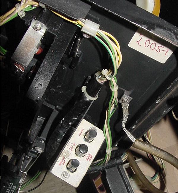
Inside the coin door is a bank of three switches used for the diagnostics (from bottom
to top, "HighScore Reset", "Auto Up/Manual Down", "Advance") on Banzai Run.
|
|
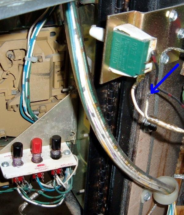
What if the Diagnostic Switches Don't Work?
If the diagnostic switches inside the coin door don't work,
there's some simple things to check.
- Coin door must be open. There's a switch that opens when the
coin door is open. This switch needs to work for the diagnostic buttons
to work properely. Also there's a common wire on this switch that goes
to the diagnostic buttons - if this wire is broken, the diag switches won't work
(see the picture below.)
- Broken common wire on the three diagnostic switches. This too is a common
problem, where a wire comes off one of the switch lugs.
- Bad switches. This is pretty common, the switches just wear
out or get corroded. Replacement is best, but sometimes a couple drops of 3-in-1
oil on the shaft of the switch and some rapid "exercise" can bring a dead switch
back to life.
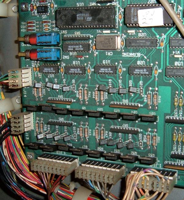
- CPU board connectors 1J13/1J14. On the CPU board at the lower left corner
there are two 4-pin connectors. The lower connector (1J13) should have black wires - this
is a common ground connector. The one right above it (1J14) is the diagnostic
switch connector. Since these two connectors are pinned alike, they are easy to
get mixed up. If this happens, the game will go into diagnostics and will continually
"advance" through the audit/adjustment menu. Mixing up these two connectors will not
cause any damage - just the game's diagnostic switches won't work.
Why don't the diagnostic switches work? Here the broken wire on this F-14 coin door
switch is the problem.
|
|
System 9 and System 11 (not A, B or C) LED Codes.
System 11 games (with no letter suffix) like High Speed,
Grand Lizard, Road Kings and all the system9 games have a 7 segment
display instead of a LED lamp that flashes. The software on these
games (only) supports the 7-segment LED display. If an early system11 CPU
board is transplanted into later games, the 7-segment display will
be irrelevant. But here's the LED segment display codes for the
early sys11 and sys9 games:
- 0 = Test Passed (games goes to attract mode). BUT if zero displayed
during memory chip test, this means the blanking circuit is bad!
- 1 = CPU board lockup. Check memory protection circuit and U25 RAM.
- 2 = U27 game EPROM bad.
- 3 = U26 game EPROM bad.
- 4 = Unused.
- 5 = Blanking signal "stuck". Could be coin door is closed and
memory protection circuit faulty, or U25 RAM bad. If the coin door
is closed, open the door and if all is good, a "0" code should appear
(this may require press the Diag button again with the coin door open).
- 7 = No 12 volts to CPU board, or bad/blank game EPROM(s).
- 8 = Blanking Circuit is working correctly (displayed during memory chip test only).
- No Indication = System failure. Check +5 volts, or U26 game EPROM bad.
Note if an early system11 CPU board is installed in later
sys11a,b,c games, the segmented LED will not work correctly, and
will give 'garbage' results. This is because the ROM software
is expecting the two LED lights (plus a +5v LED), and not a segmented LED display.
On system 9 games (Space Shuttle for example)
I have seen a power-on LED code "7". This was caused by
mixing the dreaded white and black playfield connectors,
causing severe damage to the CPU board (the game and sound ROMs will fry,
as will at least one PIA and several support TTL chips). When assembling the two large
rectangle black and white connectors, make sure the wire colors match
(the plug colors should also match, but double check the male/female
plug wire colors). If these two plugs are reversed, a quick way to tell
is the right flipper will energize as soon as the game is turned on
(but hopefully you have not turned the game on with these two plugs reversed!)
System 11 diagnostic switches on the CPU board. The top button (SW1) is for the
sound board, the bottom button (SW2) is for the CPU board. Also shown are
the 4 pin connectors J13 and J14 (lower left), which can be mixed up, making
the diagnostic coin door switches inoperative.
|
|
CPU Board Test Switches.
There are two test switches on the left side of the CPU board. The bottom switch (SW2)
labeled "CPU" performs a "Memory Chip Test" (the same test performed when the
game is first turned on). You can press this button at any time to
do a CPU test (as explained below).
System 11a, 11b, 11c Diagnostic Flashes.
These games do not have a 7 segment display. Instead there is a
LED which indicates the memory chip test being preformed.
To start the memory chip test, turn the game on or
press the bottom CPU diagnostic switch button SW2 on the left side of the CPU board.
Quickly count the CPU board LED flashes of the middle (diagnostic) LED, and compare
them to the follow chart.
| Flash |
Display Message |
Explanation |
| 1 |
U25 RAM Failure |
U25 RAM could not be used. No other tests are performed; the game is
locked here until the problem is fixed. |
| 2 |
Memory Protect Failure |
This message means: (A) the coin door may be shut; (B) the Memory
Protect switch may be stuck in the ON position; (C) the Memory Protect
logic is protecting the audit memory; (D) a U25 RAM failure is occurring.
Note this test assumes the coin door is OPEN since this test is initiated ONLY by
pressing the CPU diagnostic switch (SW2). |
| 3 |
U51 PIA Failure |
6821 PIA at U51 has failed (score display circuit). * |
| 4 |
U38 PIA Failure |
6821 PIA at U38 has failed (switch matrix, spec sol A&B) * |
| 5 |
U41 PIA Failure |
6821 PIA at U41 has failed (score display data 1J2, spec sol B&C). * |
| 6 |
U42 PIA Failure |
6821 PIA at U42 has failed (sound board). * |
| 7 |
U54 PIA Failure |
6821 PIA at U54 has failed (lamp matrix, spec sol E&F). * |
| 8 |
U10 PIA Failure |
6821 PIA at U10 has failed (Sound outputs, solenoid drives, flipper relay). * |
| 9 |
IRQ Failure |
IRQ has malfunctioned. It may be missing or too slow or too fast. |
| 10 |
U27 ROM Failure |
The ROM (or EPROM) at U27 did not pass its internal checksum. This could
be a ROM failure, or its associated components and connections may be
causing this problem. U26 ROM test is skipped. |
| 11 |
U26 ROM Failure |
The ROM (or EPROM) at U26 did not pass its internal checksum. |
* Alternatively, the PIA's associated connections or components are causing
the PIA to appear bad.
Low +5 Volts Causing U10 PIA LED Error.
On a F14 Tomcat and other sys11 games,
occasionally a power-on U10 PIA failure error is seen
via the diagnostic LEDs, but the game still play fine after a sucessful
power-on (the U10 error would happen spuratically).
This can often be attributed to an issue with the +5 volts being
too low, below 4.9 volts DC (check the +5/12 volt power supply filter cap, as
this may be the problem). If this issue is not fixed, it can
fry the special solenoid circuit and other circuits.
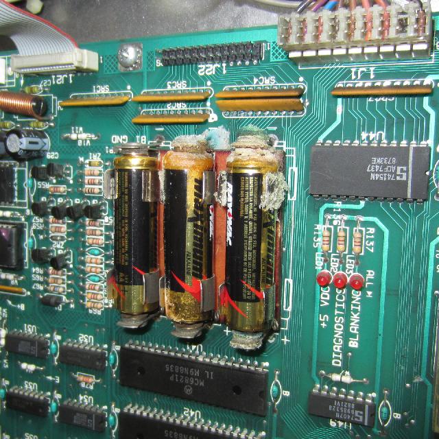
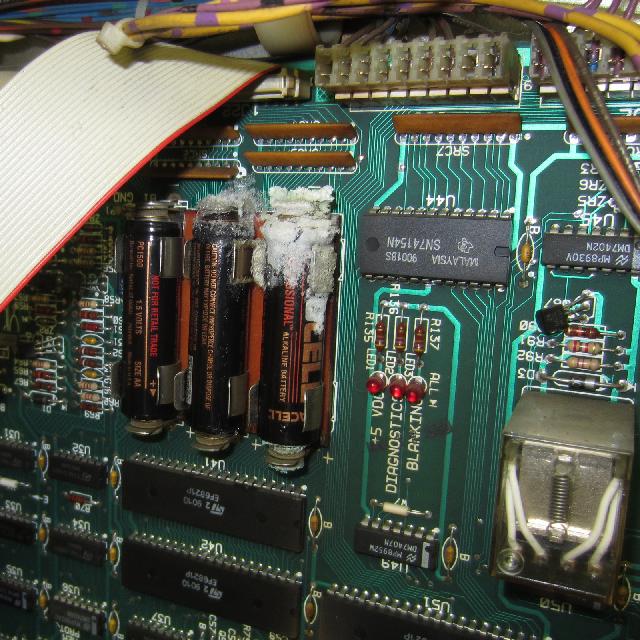
3g. When thing don't work: Battery Corrosion Issues.
Unfortunately, the memory battery back up used on all system11 CPU boards
are three AA batteries. These have a habit of leaking. Since they are
mounted on the CPU board dead top center, their ability for circuit
board damage is immense. To make things worse, there are a number of
very small board traces that go right under and around the battery
holder. This makes repair of battery corrosion more difficult.
Battery corrosion on a Williams system11b Cyclone.
More battery corrosion on a Williams system11c Rollergames.
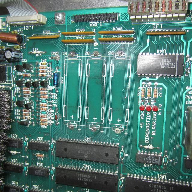
Battery corrosion on a Williams system11b Cyclone,
underneath the battery holder. Notice the fine traces
that are easily compromised by corrosion.
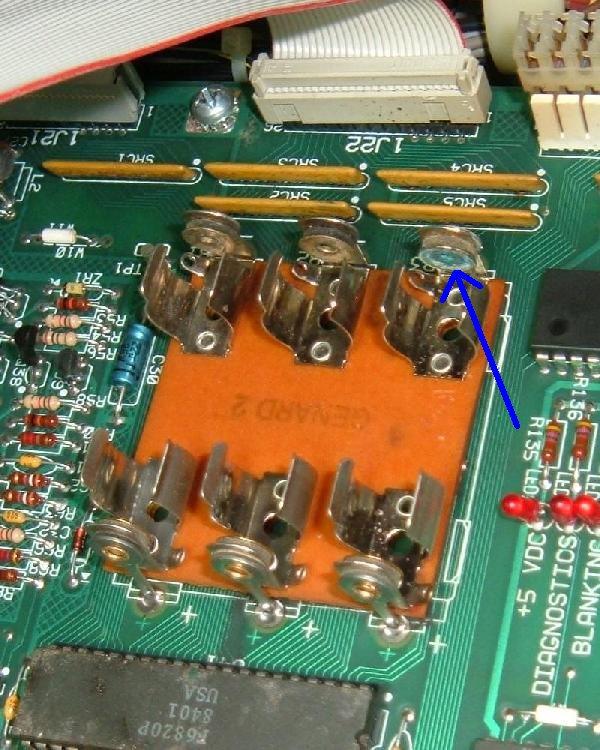
Minor damage to the battery holder only is often fixable.
But to install the same style battery holder again, seems
like making the same mistake over.
Light battery corrosion on a system11 battery holder.
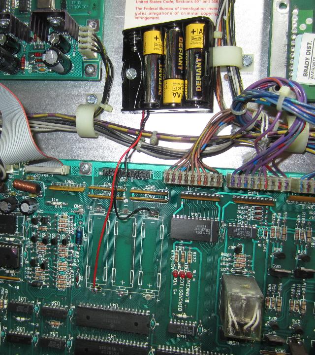
Remote AA battery packs work well, and are very inexpensive
and easy to implement. Below shows a picture of this set up.
Though it gets the batteries off the board, it does not fully
solve the battery corrosion problem. As batteries corrode,
they "out gas" noxious fumes, which are heavier than air.
This means the items below the batteries are often effected.
It's good to have batteries off the board - using a solution
like shown below gets you about 98% there (which is pretty good!)
But there is an even better solution to the battery problem.
Remote battery mount on a Williams system11b Cyclone.
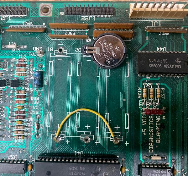
Lithium Coin Battery.
Something I have found to be an excellent, yet easy to implement
and very inexpensive, is using a Lithium coin battery instead
of the AA batteries.
Using a CR2032 Lithium coin battery on a Williams system11b board.
The positive side of the coin battery goes to the left, as seen
in this picture. The yellow jumper wire on the bottom two AA battery
terminals is required to make this work.
A Lithium coin battery holder costs less than a dollar, as does the
CR2032 battery. Now yes if you go to the local drug store, you will pay
through the nose for a CR2032 Lithium battery. But most online
sources (like BGmicro.com) sell
both the battery holder and battery for a song. The battery holder
does require a single 1/16" hole to be drilled in the board
to accomodate the negative lead of the battery holder. That isn't
mandiatory, but it does make for a better looking installation
(as seen above.)
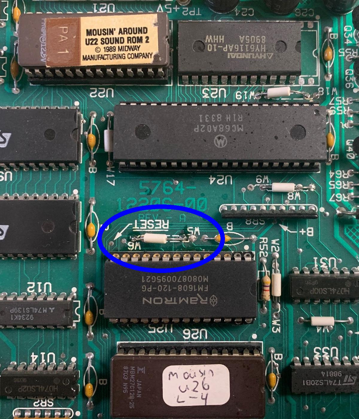
RAMTRON usage at U25.
A Ramtron style chip can be used for the game RAM at U25 instead
of the stock 6116 RAM chip. That advantage to the Ramtron is
no batteries are needed on the CPU board! A lot of people are doing this
modification so they never have battery corrosion problems, and never
have to remember to change a battery. The Ramtron is a 6264 style
RAM. That is it's 28 pins not 24 pins like the original 6116 chip. You will have
to unsolder the original 6116 RAM from the CPU board at position U25,
and install a 28 pin socket. The CPU board is already set up for a 28 pin chip
(just the right most four pins are not populated.) So once the original 6116 chip (24 pins)
is (cleanly!) removed, a 28 pin socket can be installed. Then the Ramtron plugs directly
into this 28 pin socket. Also the CPU board needs one jumper changed (to let the
board know you're using a 6264 style RAM, instead of the stock 6116 RAM.)
6264 at U25: W6=in, W5=out
Using a RamTron chip at the game RAM position U25. Jumper W6 (installed) and W5 (removed)
will be needed to do this.
Battery Corrosion.
So what if the AA batteries did corrode, and have caused problems
on the CPU board? This is pretty common. The traces underneath
the original battery holder and to the north/south of it will be
at risk. These are the PIA lines going to the ribbon cable connectors
from PIA U41/U42 and go to ribbon cable connectors J21/J22. They
pass through some resistor/capacitor SIP networks along the way too
(which are often damaged by battery corrosion.)
If you game is missing some sounds or the display is missing some
segments, battery corrosion is something to look for. With this
in mind, here's the pinout from the J21 (sound) and J22 (score
display) connectors to the PIAs u41 and u42. If there's any corrosion
these connections should be "buzzed out" using a DMM set to continuity tone.
If a line is missing, it can usually be repaired with some wire wrap.
Note the ribbon cable connectors are labeled as to pin1 and the last pin
on the circuit board. (The numbering
moves vertically down, and then to the left, with pin1 at the top right.)
Sound Ribbon Cable J21 to PIA connections.
- J21 p1 - ground
- J21 p2 - blanking to J22 p2 and to U50 p12 (and other chips)
- J21 p3 - u42 p10
- J21 p4 - u42 p11
- J21 p5 - u42 p12
- J21 p6 - u42 p13
- J21 p7 - u42 p14
- J21 p8 - u42 p15
- J21 p9 - u42 p16
- J21 p10 - u42 p17
- J21 p11 - u41 p18
- J21 p12 - u42 p18
- J21 p13 - u42 p19
- J21 p14 - u41 p34
- J21 p15 - u41 p40
- J21 p16 - u42 p40
- J21 p17 - u42 p21 and U41 p21
- J21 p18 - u42 p39
- J21 p19 - u42 p25
- J21 p20 - No connection
Display Ribbon Cable J22 to PIA connections.
- J22 p1 - ground
- J22 p2 - blanking to J21 p2 and to U50 p12 (and other chips)
- J22 p3 - u42 p2
- J22 p4 - u42 p3
- J22 p5 - u42 p4
- J22 p6 - u42 p5
- J22 p7 - u42 p6
- J22 p8 - u42 p7
- J22 p9 - u42 p8
- J22 p10 - u42 p9
- J22 p11 - u41 p2
- J22 p12 - u41 p3
- J22 p13 - u41 p4
- J22 p14 - u41 p5
- J22 p15 - u41 p6
- J22 p16 - u41 p7
- J22 p17 - u41 p8
- J22 p18 - u41 p9
- J22 p19 - u41 p10
- J22 p20 - u41 p11
- J22 p21 - u41 p12
- J22 p22 - u41 p13
- J22 p23 - u41 p14
- J22 p24 - u41 p15
- J22 p25 - u41 p16
- J22 p26 - u41 p17
As for actual battery corrosion removal, I have found the only
effective way to deal with this is using a bead blaster.
The media is small ceramic beads. This gets rid of the corrosion,
allows for soldering, and looks good. After bead blasting the
effected area, a very light spray clear coat of lacquer or
similar product is applied. This locks out air and prevents
the area from corroding again.
3h. When thing don't work: Fixing a Dead or Semi-Dead CPU Board.
Skip to using various Test EPROMs for
testing the system11 cpu board. There are several different test ROMs
by various individuals like Leon, Ed Cheung, Williams, Germans.
Sometimes your game is just dead. No CPU flashes, nothing. This can be
caused by a number of problems. You'll need to do some "low level" diagnostics
work, and it is not for the casual pinball fixer. At minimum you'll
need a DMM (digital multi-meter), a logic probe, and ideally an oscilliscope. What follows is the order
and things I check first.
Depending on the era of system11 board, there may be a segmented display
that shows error messages. Only High Speed,
Road Kings, Grand Lizard and system9 games have software that supports this.
If an early system11 CPU board with a 7-segment display is transplated to a
later system11 game, the segmented display info is irrelevant garbage.
- 0 = Test Passed (games goes to attract mode). BUT if zero displayed
during memory chip test, this means the blanking circuit is bad!
- 1 = CPU board lockup. Check memory protection circuit and U25 RAM.
- 2 = U27 game EPROM bad.
- 3 = U26 game EPROM bad.
- 4 = Unused.
- 5 = Blanking signal "stuck". Could be coin door is closed and
memory protection circuit faulty, or U25 RAM bad. If the coin door
is closed, open the door and if all is good, a "0" code should appear
(this may require press the Diag button again with the coin door open).
- 7 = No 12 volts to CPU board, or bad/blank game EPROM(s).
- 8 = Blanking Circuit is working correctly (displayed during memory chip test only).
- No Indication = System failure. Check +5 volts, or U26 game EPROM bad.
System 11a, 11b, 11c Diagnostic Flashes.
These games do not have a 7-segment display. Instead there is a
diagnostic LED which indicates the memory chip test being preformed.
To start the memory chip test, turn the game on or
press the bottom CPU diagnostic switch button SW2 on the left side of the CPU board.
Quickly count the CPU board diagnostic LED flashes, and compare
them to the follow chart.
| Flash |
Display Message |
Explanation |
| 1 |
U25 RAM Failure |
U25 RAM could not be used. No other tests are performed; the game is
locked here until the problem is fixed. |
| 2 |
Memory Protect Failure |
This message means: (A) the coin door may be shut; (B) the Memory
Protect switch may be stuck in the ON position; (C) the Memory Protect
logic is protecting the audit memory; (D) a U25 RAM failure is occurring.
Note this test assumes the coin door is OPEN since this test is initiated ONLY by
pressing the CPU diagnostic switch (SW2). |
| 3 |
U51 PIA Failure |
6821 PIA at U51 has failed (score display circuit). * |
| 4 |
U38 PIA Failure |
6821 PIA at U38 has failed (switch matrix, spec sol A&B) * |
| 5 |
U41 PIA Failure |
6821 PIA at U41 has failed (score display data 1J2, spec sol B&C). * |
| 6 |
U42 PIA Failure |
6821 PIA at U42 has failed (sound board). * |
| 7 |
U54 PIA Failure |
6821 PIA at U54 has failed (lamp matrix, spec sol E&F). * |
| 8 |
U10 PIA Failure |
6821 PIA at U10 has failed (Sound outputs, solenoid drives, flipper relay). * |
| 9 |
IRQ Failure |
IRQ has malfunctioned. It may be missing or too slow or too fast. |
| 10 |
U27 ROM Failure |
The ROM (or EPROM) at U27 did not pass its internal checksum. This could
be a ROM failure, or its associated components and connections may be
causing this problem. U26 ROM test is skipped. |
| 11 |
U26 ROM Failure |
The ROM (or EPROM) at U26 did not pass its internal checksum. |
* Alternatively, the PIA's associated connections or components are causing
the PIA to appear bad.
All of the above failures (except #9) may mean that the device has failed. But it could
also mean that the 6802 is unable to communicate with another chip.
For example, if the CPU is attempting to checksum the
game ROM u27, but one of the 8 data lines leading to u27 is cut,
the wrong data will be received by the 6802 and the checksum test will
fail (even though the ROM may be fine.)
Also note a u25 RAM failure can occur without actual 6116 RAM failing. One of the most
common reasons is lack of power to the u25 RAM chip.
If the D1 diode (1N5817) goes open, power will no longer have a path
to the u25 RAM. However if the D2 diode (1n4148) blocking diode is Ok, and the
battery holder and batteries are good, power will stay to the u25 RAM.
Even though the batteries will die prematurely if diode D1 has shorted (because
the batteries are trying to power the entire board.) Another reason
why u25 RAM is no longer powered by the +5v power is due to a cut trace
(often caused by battery corrosion.)
As a side note, a side effect to the U25 RAM failure blink code is that the
blanking LED can blink 10 times after the single blink from the diagnostic LED.
Low +5 Volts Causing U10 PIA LED Error.
On a F14 Tomcat and other sys11 games,
occasionally a power-on U10 PIA failure error is seen
via the diagnostic LEDs, but the game still play fine after a sucessful
power-on (the U10 error would happen spuratically).
This can often be attributed to an issue with the +5 volts being
too low, below 4.9 volts DC (check the +5/12 volt power supply filter cap, as
this may be the problem). If this issue is not fixed, it can
fry the special solenoid circuit and other circuits.
How did your game "die"? (the "cascading" effect)
The way in which your CPU board died can be important.
For example, did a coil lock on just before the game died?
If so, more than the driver transistor could have been effected.
It could have "cascaded" back beyond the driver transistor,
and to the driving PIA itself. If the PIA failed, this can
cause a CPU board to be "locked up".
Here's another example of the cascading effect. Say you were
playing a game, and the high voltage for the score displays
blew a fuse, and the game locked up. Again, this problem could
have back-tracked it's way to the CPU board, and killed the
PIA.
If you don't know how your game died (for example, you just bought
the game already "dead"), carefully look for evidence of
problems. What fuses were blown? Look at the PIA chips and notice
any "black ring" in the center of the chip (indicating the PIA
got really hot at one time).
The Six PIA's and What they Control.
The 6821 PIA chips at U10, U38, U41, U42, U51, U54 can stop a CPU board
from booting. Note all six PIA's connect to the main 6802 CPU reset and IRQ circuits.
Here's what each of the six PIA's controls:
- U10: Sound output selects, solenoid drives, CPU board flipper relay K1.
- U38: Switch matrix columns and rows, special solenoids A & D.
- U41: Score display data (1J22), special solenoids B & C.
- U42: Sound board (1J21)
- U51: Score display circuit (1J1, 1J2, 1J3).
- U54: Lamp matrix columns and rows, special solenoids E & F.
In additions there is one more sound PIA at u9 which is controlled
by a separate 6802 processor. If this PIA has failed, the game
will not have speech or sound (though it could still have background
music, since hat is handled by a separate sound board.)
Examine Prior Repair Work.
A good thing to do with any non-working game that you just
acquired is to look for prior repair work. Examine the back of the
CPU board for example, looking for solder flux (which indicates
a component was removed and replaced). Buzz out all the traces
on any new socket or component installed to connecting components
(you'll need the schematics for this). This will make sure no traces
were broken in prior repairs. Other people's "hacks" can often be
the only thing wrong with a board!
Remove all Unneccessary Connectors Before Starting.
Before you power on a locked up CPU board, it's a good idea
to remove all connectors from the board that aren't needed.
This will limit the "cascading" effect that could possibly
damage other boards. Here is a list of CPU connectors:
- 1J1: Display Digit Strobe
- 1J2: Display Digit Strobe
- 1J3: Display BCD
- 1J4: Lamp matrix +18 volt power
- 1J5: Lamp matrix ground
- 1J6: Lamp matrix rows
- 1J7: Lamp matrix columns
- 1J8: Switch matrix columns (mechanical)
- 1J9: Switch matrix columns (opto, sys11 only)
- 1J10: Switch matrix rows
- 1J11: Solenoids 1-8 (Q22-Q25, Q30-Q33)
- 1J12: Solenoids 9-16 (Q6-Q9, Q14-Q17)
- 1J13: Solenoid ground.
- 1J14: Direct switches (coin door diagnostic switches)
- 1J15: Speaker outputs (system 11, 11a only)
- 1J16: Volume control (system 11, 11a, 11b only)
- 1J17: CPU POWER (ground, +5, +12, -12 volts)
- 1J18: Special solenoids switches 1-6 (not used on games Big Guns and later)
- 1J19: Special solenoids 1-6
- 1J21: Ribbon cable to Audio board
- 1J22: Ribbon cable to Master display board
The only connector that should be attached is 1J17 (CPU power). This
connector provides the power to CPU board, and is the only one
needed to measure voltages and to check for board signals.
Check for Battery Corrosion.
It's a big problem, those three AA batteries right dead center top
of the CPU board. And they can cause all kinds of havoc if they
leak, ruining the PIA chips directly below the batteries, and
the board traces going to these chips.
Move to the Work Bench.
It is not very easy to
try and fix a dead CPU while it's still in the game. You are
much better off fixing it on your workbench. Fixing it on the workbench
means you have issolated the bad CPU from the rest of the game (including
it's power supply!) This can be done using a computer power supply
with +5 and +12 volts.
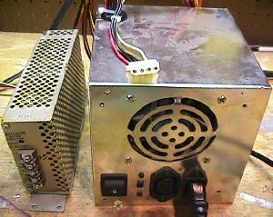
Left: a video game switching power supply. All voltages
and ground are clearly marked on these.
Right: a computer power supply. You'll have to check the
power supply lines to get the right voltages on these.
But 99% of the time, red = +5 volts, yellow = +12 volts,
and black = ground. Double check them with your DMM.
|
|
The best power supply for your CPU is one of those switching video
game power supplies, or an old computer power supply. You need to get
+5 and +12 volts, and ground from the power supply. On computer power
supplies most of time red = +5 volts, yellow = +12 volts,
and black = ground.
Hook up the power supply to the CPU board using aligator clips.
Here's the pinout for the power connector 1J17 on the CPU board.
- CPU 1J17 pins 1,2,3 = ground
- CPU 1J17 Pins 4,5,6 = +5 volts DC
- CPU 1J17 Pin 7 = key (not used)
- CPU 1J17 Pin 8 = -12 volts DC (only used for audio, IGNORE)
- CPU 1J17 Pins 9 = +12 volts DC
With the CPU on the workbench and issolated from the game, you
can test the board much easier. Note the usage of -12 volts. You
do not need that voltage to test the CPU board. It is only used
for the audio section of the CPU board.
Test for Proper voltage on the boards.
Your game will never run if you don't have +5 volts
on the CPU board. But first you must test for ground on the CPU board.
To test for ground, turn the game off and set your DMM to
"ohms". Make sure you get zero ohms from the ground test point TP1 (to the
left of the batteries) on the
CPU board, to the metal shield or ground strap in the backbox.
Next set your DMM to DC volts. Turn the game on, and test for +5 volts at
TP2 on the CPU board (TP2 is to the right of chip U21). Make sure the black
lead of your DMM on ground (backbox grounding strap).
Now test for +5 volts right at the chips themselves. For example,
test for +5 volts at U15 (the 6808 CPU) at pin 8. The 2764 EPROM at U26 and
the 27256 EPROM at U27 will have +5 volts at pin 28. The 6821 PIA's
at U10, U38, U41, U42, U51, U54 will have +5 volts at pin 20.
Remember, pin 1 of all chips is by the "notch" in the chip. Also
there is usually a white "dot" printed on the circuit board
to show pin 1.
Finally, test for voltage on the power supply. Here are the test points
to check:
- P.S. TP1 = +5 volts on the power supply board.
- P.S. TP2 = ground on the power supply board.
- P.S. TP3 = +12 volts on the power supply board.
- P.S. TP4 = -12 volts on the power supply board.
Check the EPROM's.
The game EPROMs at U26 and U27 contain the boot up code for the game.
If the EPROMs are bad, the game may not even try to boot. If the
opaque tags have fallen off the quart windows on these chips, that's
a good indicator that the EPROMs may have been damaged. Ultraviolet
light can "erase" these chips, and the opaque tags block light
from entering the EPROM chips. New game EPROM's can be burned for
a nominal fee by many pinball user groups and service centers.
Usually your old EPROMs can be reused too. Another great approach
is to use Leon's Test EPROM as only one
EPROM will be needed, and it uses a minimal amount of CPU board
circuits to boot.
Replacing the CPU chip.
Early system 11 games used a 6802 CPU chip at U15. This chip is
now more difficult to buy, but can be replaced with a 6808 chip. Occassionally
the CPU chip at U15 does go bad.
Replace the RAM chip at U25 (Game RAM).
At this point I usually replace the 6116 RAM chip at U25. If this chip is
bad, this can stop the CPU from booting. This is a 2k by 8 CMOS static
24 pin RAM chip. The part number will be 2016 or 6116 or NTE2128.
Early system 11 games specify this chip as a 5177, but it can be
replaced with a 6116 instead. Jumper W5 and W6 control the RAM size.
That is, jump W5=in (W6=out) and a 6116 RAM is used. Jumper W6=in (W5=out) and a 6264 RAM is used.
Note the U25 game RAM is the battery powered RAM. That is, the three AA
batteries (if you are using those) keeps this RAM alive by supplying voltage
to pin 24 of the 6116 chip.
Check for Battery Corrosion underneath the Battery Holder.
Under the battery holder there are a bunch of lines coming from the PIA chips.
If there was battery corrosion on the CPU board in the past, these lines could
be compromised with corrosion. You will have to remove the battery holder
to see this, but it's well worth checking.
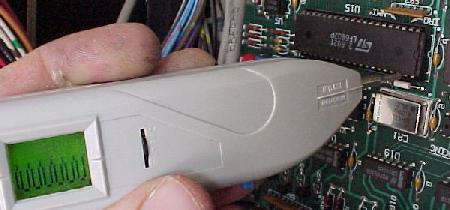
The clock signal at pin 39 of the 6808 CPU at U15, using the nifty Wittig
Technologies
(wittig-technologies.com)
osziFOX Probescope, logic
probe oscilloscope.
|
|
Check the Clock Signal.
If you have good RAM and EPROMs, and +5 volts at the CPU board, now
is time to check the "clock signal". The clock signal is generated
by the CPU board's crystal and some other components. The clock signal ends up
at the U15 6808 CPU at pin 39. Using an oscilloscope or logic probe, check
for a signal here with the game on. It should be a square wave. If all you get is a constant
low or high, you have a problem in the clock section of the CPU board.
Check the Reset Line.
The reset section's job is to hold the reset line on the U15 CPU chip (pin 40)
low for half a second or thereabouts, so the +5 volts can stablize. After this
the CPU pin 40 reset goes high, and boot process can continue.
Using a logic probe, check the "reset" line on the U15 6808 CPU, pin 40.
When the game is first powered on, pin 40 should be low for just a
moment, then go high, and stay high. If the signal goes low then high then low
then high, over and over, the game is trying to reset itself over and over.
If this is the case, there is a problem with the reset section of the board.
Note this reset line goes to PIA U10. So if this 6821 PIA chip is bad, the
CPU board may never reset. Also since the reset line is connected to each
of the six PIA's, if one of the others is bad, that can cause reset
problems too.
If the CPU board is locked up, power the board up on the workbench.
Then ground the CPU Reset line (pin 40 of U15) momentarily with a test lead.
If the board boots up, the problem is with the POR (Power On Reset) circuit.
The POR section's job is to look at the +5 and +12 volts, and make sure
they have stablized, as determined by zener diodes ZR1 (1N5996A, 6.8 volts .5 watt) and
ZR2 (1N5990, 3.9 volts .5 watt) before
starting the CPU. This is done by transistors Q34, Q36 and Q38, but
before these three transistors can work, capacitor C30 and resistors
R55 and R56 provide a delay to allow the voltage to stabilize. Only
then the /RESET line can be released.
Any of these POR components could be bad, and not causing the
CPU board to boot properly. If the board boots inconsistently,
first look at capacitor C30 (a 22 mfd 10 volt electrolytic). If you don't have
any way to test the capacitor, just clip another 22 mfd electrolytic
cap across the leads of the existing C30 cap (positive to positive, negative
to negative, a parrallel connection). Also test the resistors R55 (4.7k 1/4 watt) and R56 (10 ohm 1/4 watt),
and transistors Q34, Q36, Q38 (2N4401).
Reset Section and Games that Won't Boot Consistently.
Another problem sometimes seen is a game that will "turn on"
inconsistently. For example, after the game is off for a period of time,
it is powered up, yet the game does not boot. Then it is turned off
and back on, and it comes on. This is usually a reset section problem
on the CPU board, and is capacitor related. Check the 22mfd cap at C30,
and perhaps the 100mfd cap C29, as mentioned above.
Check the 6821 PIA Chips with a DMM.
Now test the PIA chips U10, U38, U41, U42, U51, U54 (and U9 if pre-sys11c)
with a DMM. With the game off, set your DMM to
the "diode" setting, and put the red lead on ground (pin 1).
Then put the black lead on pins 2-9 (PA0-PA7) and pins 10-17 (PB0-PB7),
one by one. You should get a reading between .5 to .6 volts (only exception
being U51 pin 9 showing zero if tested in the board). If you get
a zero reading (a short) for any pin 2 to 17, replace that PIA.
This test can be performed with the PIA chips in the board.
This isn't a fool-proof testing method, but it will show a short
in a PIA chip (I have fixed a number of bad PIAs using this method).
Another way to check the 6821 PIA chips is to remove the PIA chips
(with the game off), one at a time,
and put them in a working CPU board (in the same chip position).
This way you can see if putting in the questionable PIA chip causes
the otherwise working board to fail. Another great way to check the
PIA chips is to use Leon's Test EPROM.
"Heat Checking" the PIA's.
This is a really crude way of checking the PIA's. With all
the supporting connectors disconnected, turn the game on.
Now carefully and gently touch each of the six 6821 PIA's
at U10, U38, U41, U42, U51, U54. Are any of them warm?
If so, this indicates a problem with the PIA. Also look
for a "black ring" on the center of the PIA, indicating
a heat problem before. Also heat check the 6116 RAM memory
at U25 too.
Check the 74LS244 chips at U11 and U13.
If either of these two chips is bad, the game will never
boot. Check both of these chips using your DMM with the game off. Set your DMM to
the "diode" setting, and put the red lead on ground (pin 10).
Then put the black lead on pins 1-9 and pins 11-18.
You should get a reading between .4 and .6 volts. If you get
a short (zero) reading, replace that chip.
The Blanking Signal.
The blanking circuit is a protection circuit. If the CPU board does not boot
properly, it will shut down many functions on the
board (including the score display strobes, so the display glass isn't
damaged). The blanking circuit must be inactive for the CPU board to
boot and function, and is shown by the blanking LED (which should always
be on). The blanking circuit is reset by the display strobes.
Blanking problems can also be caused by a short in any connecting logic chips.
The blanking signal is the CPU board's flag to the Driver board that
the CPU has booted properly. But wait, I know you are saying, "there
isn't a driver board, what are you talking about?" Actually there IS a
driver board. Step back to Williams' system3 to system7 and remember
the CPU and driver board were separate, linked by a 40 pin interconnector.
With Williams system9 and system11, Williams combined the CPU and driver
board into a single physical board, eliminating the problematic 40 pin
interconnector. Hence on System11 logically the CPU and Driver boards are two
separate devices, but physically they reside on the same printed circuit board
(which increases reliability).
The blanking signal is easily seen on the CPU board by the blanking LED.
At power on, blanking is low very momentarily. As the CPU finishes
booting, blanking goes high, enabling the driver board and
turning the blanking LED on. Often
the blanking signal will never go high or will immediately be
high right at power-on (no initial blanking low signal).
If the blanking signal is always high even at first power-on,
this can possibly cause a brief energizing of all the solenoids and the flipper relay.
This will usually blow the game's solenoid fuse.
Often this is the 555 timer chip at U43 that is bad,
the Q50 transistor (2N4403), and/or capacitor C58 (1uF electrolytic).
If you look at the schematics, the blanking signal is actually
tied to the reset signal on cpu U15 pin 40 reset. After the game
boots, the U15 pin 40 reset goes high, and feeds the 555 timer U43 pin 4.
The timer output U43 pin 3 becomes the blanking. The center leg of Q50 (2n4403)
should be about 3v, and the bottom leg of Q50 about 1.2 volts. If this isn't
true the cap at C58 is suspect.
There's more though... The blank signal drives a ton of TTL chips.
Though rare one of these chips could fail and hold the blanking low.
Here's the list:
- U17 pin 2,4,10,13 (coil blanking)
- U18 pin 2,4,10,13 (coil blanking)
- U19 pin 2,4,10,13 (coil blanking)
- U20 pin 2,4,10,13 (coil blanking)
- U52 pin 2,5,10,13 (lamp blanking)
- U53 pin 1,5,9,13 (lamp blanking)
- Connector J3 pin 12 (displays)
- U55 pin 1 (becomes inverted signal for sound/display blanking J21p2 and J22p2)
A way to test the blanking signal is to boot the CPU board
with only +5 volts and ground (no +12 volts). This will
keep the reset line low, and hence the blanking signal
should also be low. If blanking is high there is a problem
in the blanking circuit. Check the U43 the 555 timer chip
and Q50 2N4403 transistor - these are the guts to
the blanking circuit. Don't forget cap C58 (1mfd), as it
does fail, and it this happens, will keep the blanking signal low.
Note the blanking signal can be checked at the 555 timer chip U43 pin 3
(it should be high.)
Bad IRQ.
If the CPU is booting up, and stops after the 9th flash, there is an IRQ problem.
This can be attributed to a number of problems. Use a logic probe on the
CPU IRQ line (pin 4 of the 6808 CPU at U15) and see if it is pulsing. If not, it could be
the ROMs (unlikely if you got to flash #9), or chips U36 (7404), U35 (74LS10)
or U29 (4020), which actually does the IRQ counting.
Testing for Pulsing Address and Data Lines.
At this point the next step is to look at the address and data lines,
and to make sure they are pulsing. A missing address or data line
will definitely make a CPU board not run! To do this work you will
need a logic probe or a scope - in most cases a logic probe works fine.
If a line is missing that usually means a broken trace, bad socket,
or the chip itself is bad.
Test for the following signals at the chips listed below.
U15 (6802/6808) CPU Chip.
- u15 pins 9-20 = a0-a11, pulsing
- u15 pins 22-25 = a12-a15, pulsing
- u15 pins 26-33 = d7-d0, pulsing
- u15 pin 34 = R/W, pulsing
- u15 pin 39 = clock, pulsing
- u15 pin 40 = reset, high
U26 (27128) EPROM Chip.
- u26 pins 3-10 = a7-a0, pulsing
- u26 pins 24-25 = a9-a8, pulsing
- u26 pin 21 = a10, pulsing
- u26 pin 23 = a11, pulsing
- u26 pins 11-13 = d0-d2, pulsing
- u26 pins 15-19 = d3-d7, pulsing
U27 (27256) EPROM Chip.
- u27 pin 2 = a12, pulsing
- u27 pins 3-10 = a7-a0, pulsing
- u27 pins 24-25 = a9-a8, pulsing
- u27 pin 21 = a10, pulsing
- u27 pin 23 = a11, pulsing
- u27 pins 11-13 = d0-d2, pulsing
- u27 pins 15-19 = d3-d7, pulsing
U25 (6116) RAM Chip.
- u25 pin 1-8 = a7-a0, pulsing
- u25 pin 9-11 = d0-d2, pulsing
- u25 pin 13-17 = d3-37, pulsing
- u25 pin 19 = a10, pulsing
- u25 pin 22-23 = a9-a8, pulsing
- u25 pin 21 = R/W, pulsing
U10, U38, U41, U42, U51, U54 (6121) PIA Chips.
- pins 26-33 = d7-d0, pulsing
- pin 21 = R/W, pulsing
- pin 34 = reset, high
Leon's Test EPROM Chip.
Now is a good time to use Leon's test chip installed at U27.
(Info on this can be found here.)
If the game boots with Leon's chip, the LEDs and flipper relay
will "flash" on and off about once a second. Using a test LED
or a scope, the outputs of the six PIA chips (pins 2-17) can be tested
to see if they pulse high and low (note on PIA u38 only the switch
rows need to be shorted for this test to work.) A bad PIA can
stop the CPU board from booting, but with Leon's chip, this
can be tested and fixed.
What if the CPU board boots with Leon's test EPROM, but
doesn't work with the game ROMs? (That is, only the +5 LED is lit.)
This can be caused by a bad IRQ signal, since Leon's test chip does
not care about the IRQ. Often the problem is PIA u51 (pin4), chip u44 (74154),
and/or chip u36 (7404).
The CPU still doesn't boot, now what?
At this point, things get real complicated. Perhaps sending
the board out for repair to a professional board repair locations
is appropriate at this point.
System 9 Reset Section Componenets.
If battery corrosion has made replacing all the reset components on a
System 9 CPU board necessary, here are the parts that typically need
to be replaced. This information thanks to Seymour Shadow.
- (4) 2N4401 (Q1,Q2,Q3,Q5)
- (1) 2N4403 (Q4)
- (1) 1N5235B or 1N5996 (ZR1), 6.2 volt zener diode.
- (3) 100 mfd 25 volt electrolytic (C2,C5,C7)
- (5) .001 mfd (C1,C3,C4,C6,C8)
- (2) .01 mfd (C10,C11)
- (1) 22 mfd 10 volt electrolytic (C9)
- (1) 10k 1/2 watt (R1)
- (4) 1k 1/2 watt (R2,R3,R8,R11)
- (1) 4.7k 1/2 watt (R4)
- (1) 10ohm 1/2 watt (R5)
- (2) 390ohm 1/2 watt (R6,R10)
- (2) 220ohm 1/2 watt (R7,R9)
- (1) 47ohm 1/2 watt (R12)
- (1) 56ohm 1/2 watt watt (R13)
- (2) 1N4148 (D3,D2). Note D2 was actually a 1N5019,
which is no longer available. This is only the battery
blocking diode, so a 1N4001 or 1N4148 can be used instead.
3i. When thing don't work: CPU Test EPROMs and Game ROMs.
German System 11 Test EPROMs.
This is the most complicated test ROMs I have seen for the system11 board.
But it's also the reliable. It will find problems other test ROMs will not.
This includes two test 27256 EPROM images for u26 and u27 (though the u26 ROM is optional, see instructions.)
German u27 available here and
German u26 available here and
PDF instructions availiable here.
Williams System 11 Test EPROM.
Williams has a CPU test fixture EPROM image available. Basically this
provides slightly more in-depth diagnostics for any system 11 game. You will
need to have it burned into a 27256 EPROM though, using an EPROM programmer.
The Williams test 27256 EPROM image
is available here.
This test EPROM plugs into the CPU at U27 (make sure you install it with
the EPROM "notch" pointing to the right). You can keep the existing
game EPROM installed at U26 (you don't need to remove it). The game will
boot with the test EPROM just like the game EPROM does. There is even
a standard "attract" mode (which states you have the "test fixture" EPROM
installed.
To run the diagnostics, just enter the diagnostics as you normally would.
Have the center coin door red button in the down position, and press
the black button closest to the coin door. Then press the red button
again to the up position, and use the black button closest to the
coin door to move from test to test.
The diagnostics in the test EPROM aren't much different than the standard
diagnostics available in all game EPROMs.
Leon System 11 CPU Test EPROM.
Leon Borre (RIP)
has also developed a System 11 test EPROM and a testing procedure to use
with his EPROM. His test EPROM will verify the
CPU chip, the memory chip and all connected PIAs. The PIAs
(there are seven 6821) are used to send all signals to the external
circuits, to the displays, solenoids, lights and via the switch matrix
to all switches. When the CPU and PIAs are fine, it's almost certain
the CPU board will boot, and other problems can be easily found using the
built-in internal system 11 tests. Download his
Williams System 11 version5 test EPROM file and burn it
to a 27512 EPROM and install at U27. This is the same Test EPROM program he developed for DataEast,
and the test procedure (and the EPROM) is the same.
Note this EPROM is burned into a 27512, where on the system11 CPU
board the normal size is a 27256. That doesn't matter here, as the 27512 will plug
right into U27 without any modifications (and also works in the Dataeast CPU board.)
To use Leon's test EPROM, first
remove the CPU board from the machine. Now
connect the CPU board to 5 volts. A computer power supply can be easily
used for this task. Connector 1J17 pin 4 gets +5 volts, and 1J17 pin 3 gets ground.
It is also necessary to make a temporary connection with an aligator jumper wire
between the right side of zener diode ZR1 and +5 volts. ZR1 is located just to
the left of the batteries.
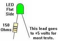
Another optional tool for this test is a "Tester LED". This is a simple
LED and a 150 ohm resistor connected as shown below.
This is connected between +5 volts and CPU chip U15 pin 15.
The "Tester LED".
|
|
Install the test EPROM into socket U27 (remove the present
game ROM and set aside). The test EPROM has a non-blocking test which
sets all outputs the seve PIAs alternating high (+5v) and then low (ground). Non-blocking
means the program will continue to run even if one of the PIAs is bad. Now
check (using a DMM or logic probe) the PIA outputs to make sure they are
alternating at about 1 second intervals between 0 and +5 volts. If none
work, the problem is on the CPU chip or the select (address/data) lines. The optional
Tester LED connected to CPU chip U15 pin 15 (address line 6) should blink in
on and off, showing the CPU chip is indeed running the test EPROM.
If the program doesn't run, we'll have to look at the basics and that's the
U15 6808 CPU chip itself. First replace the 6808 with a known good one.
Still doesn't work, then check the socket.
Now check these pins: 2, 3, 8, 35, and 40 they all have
to be positive (around 4 volt). On pin 39 there's the clock signal, on
pin 4 IRQ and on pin 5 VMA signal, and on pin 37 signal E (syncro for
external parts). These should all be around 2 to 3 volts (measured with a DMM).
If the program still doesn't work it's possible the test EPROM can't be found, or the
CPU or PIAs cannot be found.
Now remove the test EPROM from the board and power-on
the board again. The cpu will now work without a program, and it will execute all
NOP's (Non Operatieve Instructions). It goes through all its addresses from
0000-0000-0000-0000 to FFFF-FFFF-FFFF-FFFF over and over. With this we can
check all PAI address lines which should move and can be measured at U15 pins 9 to 25
(except pin 21 which is ground), and should give 2 volt. Note U15 pins 24 and 25 are
a bit less, around 1 volt. An address line which doesn't move
has a short. To test this, bend the concerning pin up, and plug the cpu chip
back in. If it works then there's a short on this address line. You can trace
this by cutting the address line at several parts and locate the defective chip
which causes the problem. The only other thing to go wrong is the selection of the
program chip or PIAs.
If there is a selection problem, we continue to work without any
program chip. Because the CPU goes through all
addresses, it will also come across every selection address of every PIA and
program chip. The selection pulses come in at these pins: for PIAs check
pins 23,24,25,35,36 which should give alternating signals (around 3 volt).
With the test EPROM installed check U27 pins 20 and 27 (2 to 3 volt). If there are
pins which don't get pulses but are always +5 or ground, then the selection has
a problem. Check the schematics to find the IC where the selection signal comes from.
One last case, there's something wrong with one or more data lines. Data lines of
the 6808 or 6802 are U15 pin 26-33. These must move and have around 2 to 3 volts. If one is
missing look for a short. Don't forget the 6808/6802 has already been replaced so
this can't be the problem, the short has to be on the data line. This can
quickly be checked by bending the pin of the data line up and see if there now
is a signal out of this pin. If so then there's a short and the buffer is
broken, because all signals go through chip U16 which buffers them. Inputs
are pins 11 to 18, outputs pins 2 to 9. If all signals go into the buffer
but not out of it, then U16 is certainly broken. If only one or two signals
don't come out then there's probably a short on these outputs. With a short
you'll have to interrupt the data line temporary and trace the IC which
causes the short.
Assuming all is good and the test EPROM is running, now it's time to test
the PIA chips.
There are seven PIAs (U51,U10,U38,U54,U9,U41,U42). On each of these PIAs
pins from 2 to 17 should be alternating from 0 to 5 volt in a one second
interval. Note there are a few exceptions:
- PIA U38 pin 2 to 9 (switch matrix) will not alternate unless 1j10 pins 1-9 are grounded.
- PIA U9 pins 10-17 (sound outputs PB0 to PB7) will not alternate.
These are connected with the D/A (digital to analog) convertor U2 and take care of
the sound. Note system11c boards do not have a U9 PIA chip.
- PIA U51 pin 9 will not alternate. This is connected via jumper W7 to ground.
- All other PIAs (U51,U10,U38,U54,U9,U41,U42) pins 2 to 17 should alternate
between 0 and 5 volts.
If one PIA output doesn't move, short it with the PIA output next to it. If both go up and
down then the PIA is broken. If both don't move, then the PIA is broken
or there's a short in the output (which didn't allow it to move in the first place). To know
which of the two problems exist, disconnect the output (cut the trace or pin, but
be sure to repair it later!) and re-check if it works.
If it moves, then there's a short, if not it's the PIA which is certainly bad.
There is also a CPU board U25 memory test. Assuming all PIAs test good, proceed to the memory test.
While Leon's test EPROM is running, push the diagnostic push button. If the memory
chip U25 is OK, the flashing of the U15 pin 15 control LED will pause for just
a moment and then continue. If the memory chip reads
bad the LED flashing will stop. As a reference,
U25 data pins 9,10,11,13,14,15,16,17 should be between 1,5 and 2,5 volts.
U25 Address pins 1,2,3,4,5,6,7,8,22 and 23 should be around 2 volts.
U25 Address A10 pin 19 should be arond 0.5 volts.
U25 Pins 12 and 20 should be 0 volts, and pin 21 about 3 volts, pin 24 about 5 volts,
pin 18 about 3.5 volts.
If you have these signals but the memory test is failing, the chip itself must be bad.
What if the CPU board boots with Leon's test EPROM, but
doesn't work with the game ROMs? (That is, only the +5 LED is lit.)
This can be caused by a bad IRQ signal, since Leon's test chip does
not care about the IRQ. Often the problem is PIA u51 (pin4), chip u44 (74154),
and/or chip u36 (7404).
System 11 Sound Test EPROM by Leon.
The sound section on the CPU board contains a separated CPU chip
(U24), a PIA (U9), a memory chip (U23), the sound EPROM (U21), the
amplifier (U1), and the D/A converter (U2).
This is only the case with CPU boards system 11 or system 11A.
On the later system 11B and system 11C boards, the sound section is no longer present on the
CPU board (moved to a separated sound board). For example on the system 11b board
there is no connector 1J15 (speaker). For this
test we can solder a speaker directly to the holes that
normally have the connector pins at 1J15.
To test this circuitry we place the 27128 Leon test EPROM in U21.
Before powering up the board, replace the normal game ROMs at U26,U27 to avoid
conflicts with the running test program. Afther power up check if the sound test EPROM is
running at U24 pin 15. The signal there is constantly alternating from 0 to 5
volts. If not the program is not running. Check the basic signals coming to the
U24 CPU chip, like the clock and reset. These are the same as the ones at
the "normal" CPU discussed above.
If the test does not run chaznge CPU chip U24.
Now the test EPROM is running, check the output pins of the PIA
U9 pins 10-17. They should alternate between 0 and 5
volts (U9 pins 2 to 9 will not move they are at 0 volt by a direct connection to the
outputs of PIA U10). If U9 pins 10-17 do not move, check first the selection signal
of the PIA U9 pin 23, as we need a pulse there. If OK change the PIA. If not check
the selection chip at U8. Inputs are at pins 1,2,3, as you need pulses at all three pins.
The output is at pin 4. Only pin 4 should be at 0 volts, all others have to be a steady +5. If
there is another pin at 0 volts, the input is bad. If all stay at 0 or 5 volt
the chip is bad.
Check the sound memory at U23.
Push the test "sound" switch once. The outputs of the U9 PIA come to an halt
for a short while, then restart. This means the memory U23 is OK.
If the U9 PIA out "dancing" does not restart the memory test is running continously.
Check the signals at the memory chip. If the signals are OK, replace the memory chip.
System 9 Test EPROM.
Leon also has a System 9 test EPROM file available:
Williams System 9 test EPROM file
(and the sound test EPROM file). Burn the CPU test file and Sound test file
into their own 27128 EPROM.
Connect the system9 CPU board to power:
- Ground at 1J17 pin 1,2,3 (any single pin will work).
- +5V at 1J17 pin 4,5,6 (any single pin will work).
- +5V to anode (top side) of VR1. VR1 is located to right of the batteries.
It is easiest to jumper 1J17 pin 6 to the anode of VR1.
- Install the CPU test ROM in socket U20
(this is the case for any system9 game regardless of jumper settings).
If the system 9 CPU board is booting properly with the Leon test EPROM installed at U20,
the CPU's LED display will show alternating 0 and 7.
There are four PIAs (U15,U14,U4 and U5), all pins from 2 to 17 will alternate
from 0 to 5 volt, which can be seen with a DMM or tester LED. There are however a few
exceptions: PIA U5 pin 9 will not change, this pin is grounded.
The PIA U15 has PA0 to PA7 used as inputs (U15 pins 2-9), to see these move
you'll have to connect J10 pins 1 to 9 to ground. Only then will
the U15 pins 2-9 outputs alternate between 0 and 5 volts.
To launch the memory test push the SW1 located near 1J14.
The alternating 0/7 on the display will stop (can stop on 7 or 0).
After a short moment it restarts alternating between 7 and 0 again.
This means memory chip U18 is good.
If the display remains on a steady 7 or 0 the memory test indicates a memory fault.
Nevertheless the memory test is running continously, and we can check if the signals
coming to the memory chip if desired.
The System 9 sound section on the CPU board contains a separated CPU chip
(U11), a PIA (U13), a memory chip (U12), and the sound EPROM (U49).
The amplifier is U59 and the Digital/Analog converter is at U48.
To test this circuitry, insert the
system 9 SOUND test 27128 EPROM in position U49.
Make sure the normal game ROM at U20 is installed
to avoid conflicts with the running test program.
Afher power on check if the test EPROM is running by examining U11 pin 15.
The signal there should be constantly changing from 0 to 5 volts.
Then check the sound PIA U13 to make sure it's outputs are alternating
between 0 and 5 volts (U13 pin 2 to 17, U13 pin 39, U13 pin 19).
Next check the sound memory at U12 (6810) by pushing the SW2 test button once
(SW2 is near 1J16). The outputs of the PIA should come to
a halt, and then restart. This means
the U12 sound memory is good. If the PIA does not restart it's output pulsing,
the memory test is running continously.
Game ROM Software.
The Williams web site has software for the game and sound ROMs which can be
programmed into EPROM. Mistake
- Pinbot, where the U22
chip is wrong in their download. You may download a corrected ZIP of this
here.
- Road Kings here.
- Grand Lizard here.
System9 ROM Jumpers w11/w12
On system9 games, remember that the game Sorceror uses two game EPROMs (added 2732 at u19),
where Comet and Space Shuttle use one 2764 game EPROM at u20. Hence a system9 CPU
board has different jumpers for Sorceror (w12=out, w11=in), than it does for
Comet and Space Shuttle (w12=in, w11=out).
- Sorceror: w12=out, w11=in
- Comet and Space Shuttle: w12=in, w11=out
Note that no change is required to use the Leon Test ROM in a Sorceror since
U20 is unaffected by the Sorceror jumper settings.
3j. When things don't work: Problems with Flippers
Flippers connect the player to the pinball
game. Having perfectly working flippers is extremely important. Here
are some common flipper problems and answers.
Remember, all flippers (regardless of the game) will have
EOS (end of stroke) switches. This tells the game a flipper is
at full extension, and to turn off the flipper high power. If
this switch is broken, it will cause problems.
Bad EOS switches should always be fixed.
Also all system 11 games will have diodes attached at the flipper
coil. Make sure these diodes are oriented like the ones pictured
below.
How Flippers Work.
Flipper coils are actually two coils in one package.
The "high power" side is a few turns of thick gauge
wire. This provides low resistance, and therefore
high power. The "low power", high resistance side is many turns of much
thinner wire. This side of the coil is important if
the player holds the cabinet switch in, keeping the
flipper coil energized. The high power low resistance side of the
coil is only active when the flipper is at rest. But when the flipper is
energized and at full extension, the low powered side
of the flipper coil is used so the coil doesn't get hot and burn.
Parallel vs. Series Wound Flipper Coils.
Flippers worked differently on games High Speed to Millionaire.
These games used a series wound FL23/600-30/2600 flipper coil. The common
lug (where both the low and high powered coil wires were
connected together) on these flipper coils
was the middle of the three lugs. Also these
coils used ONE diode across the two outside lugs. The EOS
switch on these games, when opened, enabled BOTH the high
power and low powered coils together. This style of flipper
coil did NOT use a 2.2 mfd anti-spark EOS capacitor. The problem
with this series wound coil was the "back spike" of current
that occured when the EOS switch was opened. This cause the
EOS switch to excessively wear and pit.
With the introduction of F-14 Tomcat, Williams changed to
the parallel wound FL11630 style flipper coil. This coil now used an
outside lug as the common lug (where both the low and high
powered coil wires were connected together). Also TWO diodes
were used and required on these flipper coils. This parallel
wound coil eliminated the "back spike" of current when the EOS
switch opened. It also allowed the use of a 2.2 mfd 250 volt capacitor
to further limit EOS switch sparking and pitting.
Now when the EOS switch opens,
this removed the high powered side of the
coil from the circuit. The low powered side of the flipper
coil is always in the circuit, but is essentially ignored
when the high powered side is in the circuit. This happens
because the current takes the easiest path to ground
(the low resistance, high power side of the coil).
The low power high resistance side of the
flipper coil won't get hot if the player holds the
flipper button in.
Should Series Wound Flipper Coils be Converted to Parallel Wound?
If a flipper coil needs to be replaced, the answer is "yes". Use the
newer parallel wound flipper coil, as EOS switch life will be greatly
increased. note both flipper coils do not need to be converted
at the same time. See the Rebuilding Flippers
section of this document for more information on this.
The CPU Board Flipper Relay K1 - Flippers won't turn off or on.
The flippers are only enabled during game play and in
diagnostic mode. The flipper enable relay is what turns
the ground off and on connected to the flipper coils through
the two pin connector at J19 (orange wires.)
The flipper enable relay is located on the CPU board
at K1 near the special solenoid section.
When you enter diagnostic mode, you should hear
the flipper relay K1 click on (activating the flipper
buttons). This relay is a 4PDT (4 pole double throw), 40 ohm, 6 volt relay,
and a suitable replacement can be found at Mouser.com,
part #528-7810-1 (MagneCraft #W78CSX-1, $5.50).
It connects through transistor Q67 (2N4401) and a 7402 at U50
and a 7406 at U56, and ultimately the 6821 PIA at U10 pin 19. If any of these
components are bad, the relay may not activate the flippers. First test transistor
Q67 (2n4401), as this fails the most often.
Lastly test the flipper relay itself, as the relay does go bad
(the CPU board will need to be removed to do this). A 9 volt
battery can be used on the relay's coil lugs (the two isolated
lugs from the other 12) or across the relay's snubber diode D3 (band is positive voltage.)
With the power off use the battery and check if the relay
actually pulls its armature in and out (it should click nicely).
The way this works is the U10 pin 19 PIA is high in game over mode.
When a game is started, U10 pin 19 goes low, turning the K1 relay on.
This goes to U50 pin 11/12 NOR gate (output pin 13.) This feeds to U56 pin 5 inverter
chip where the signal is reversed (output pin 6.) Then back to U50 pin 8/9 NOR gate (output pin 10)
and to the Q67 transistor and the relay.
If the flipper relay is always on, start at U10 pin 19. If this is always low
(meaning the flipper relay is told to be "on"), then the PIA chip is bad.
Move down the stream outlined checking the signal's state with a logic probem.
Note if you short U56 pin 5 and 6 together, it should change the state
of the K1 relay. That is, if the relay is on, shorting these two pins
should make it go off (or vice versa.) This is a good way to test
part of the circuit after the U56 chip.
Left: The coil diodes on a FL11630 flipper coil, F-14 Tomcat and later games.
Note the solo center blue wire and the blue wire on the right lug goes to the
EOS switch. The left lug (or gray/yellow) is the "hot" wire. The second
blue/violet wire on the right lug continues to the cabinet switch and ultimately
ground. Notice the orientation of the diode bands.
Right: The diode on a series wound FL23/600-30/2600 flipper coil. Notice the
two wire on the right lug. These are the power wires. There are two because
the power "daisy chains" to the next coil down the line. These power wires
connect to the BAND side of the diode. The EOS switch connects to the far left
lug (the ground connection), and the middle lug. The far left lug is the "thick
coil winding wire" lug.
| |
|
Flipper Diagnostics.
If the flipper(s) don't work at all...
- Check the flipper fuses. There is one fuse for each flipper.
- Clean the flipper cabinet switch contacts and the
EOS switch contacts with a small metal file. Make sure this normally closed
EOS switch is adjusted properly with a 1/8" gap at full flipper extention.
- Check for +50 volts at the flipper coil. Put your DMM on DC voltage.
Put the black lead on ground (metal side rail of game). Put the red
lead on any of the three lugs of the coil. You should get between
50 and 80 volts. No voltage means a fuse is blown, or a wire has
broken. Note on all System 11 games, there
is a separate 50 volt power supply for the flippers and some coils.
On games Fire! and before, this is a "Flipper power supply board", which
is a long thin board on the far right inside of the backbox. After Fire!
(Big Guns and later), the 50 volt poewr supply is on the Auxiliary power
driver board. These two
power supplies can have a bad bridge rectifier, or a blown fuse.
Test for voltage going into this board. If no voltage is going out, but there
is voltage going in, the bridge rectifier on this board is probably bad.
- Test the flipper coil itself. To do this, turn your game on and
leave it in attract mode. Attach your alligator test lead to
ground (metal side rail of game), and momentarily touch the other
end of the test lead to the middle lead of the flipper coil (on F-14 Tomcat and later games). The coil
should activate.
- You can also check the flipper coil with your DMM set to
ohms. With the game turned off, try this:
- Notice the three solder lugs for the flipper coil. On FL11630 flipper coils,
as used on F-14 Tomcat and later games, one of
the outside lugs has both a thick and thin coil winding attached to it.
On games High Speed to Millionaire using a FL23/600-30/2600 coil, the center
lug has both the thick and thin wires connecting to it. This is the "common" lead.
- Put one lead of your DMM on the common flipper lug (the
one with the thick and thin coil winding attached to it).
- Put the other lead of your DMM on the thick wire lug. You should get
a little more than 4 ohms. This is the high powered side of the coil.
- Put the leads of your DMM on the thin wire lug of the coil.
You'll get a litle more than 4 ohms until you
move the flipper manually to the full extended position, opening
the EOS switch. Now you'll get about 160 ohms. Note if you get more
than about 5 ohms when the flipper is at rest in this test, your EOS
switch is pitted and causing some resistance. Clean it for stronger
flippers.
- If you don't get approximately these readings, the flipper coil is bad.
Typically the hold side of the coil goes bad more often that the power side.
- Test the flipper diode(s). To do this you'll have to cut one lead
of each diode off the coil lug. Then set your DMM to the diode setting.
Put the black lead of your DMM on the banded side of the diode. You should
get .4 to .6 volts. Reverse the leads and you should get no reading.
When done, re-attach each diode lead. Note games using flipper coil FL23/600-30/2600
only have one coil diode. Games F-14 Tomcat and later use a FL11630 flipper
coil and have two diodes.
- The CPU board flipper relay K1 is not engaging. If the relay that turns the
ground on to the flippers (when a game starts) has failed, the flippers will never work.
Replace this relay or examine the logic that controls this relay. This is
a 4P, 40 ohm, 6 volt relay. It connects through transistor Q67 (2N4401)
and a 7402 at U50 and a 7406 at U56, and ultimately the 6821 PIA at U10.
If any of these components are bad, the relay may not activate the flippers.
First test transistor Q67, as this fails the most often.
If the flipper works, but "Flutters".
- When activated, doesn't hold up (the flipper "flutters"). This often means
the hold winding on the coil itself is broken. The hold winding on the coil is the thin
wire. If it is broken, you can usually see the wire has broken away
from one of the solder lugs (the middle lug should have both the
thick and thin wire attached to it). Test the coil (see above) with a DMM.
Sometimes the break can provide an intermittent connection.
- Another problem could be the EOS switch is not adjusted properly.
If the moving EOS switch blade does not have enough tension against the other
switch blade, flipper flutter can occur. Sometimes adjusting the EOS switch
with the game on and the flipper button held in is the best way (but be careful
not to short the high voltage EOS to a low voltage lane change switch!), because
wear in the flipper linkages can give wrong EOS switch measurements when moving a flipper
bat by hand.
- Also check the cabinet switches for proper tension and that they are clean.
- Lastly, try replacing the coil stop. A very worn coil stop can cause flipper flutter.
If one or both flippers are weak...
- Rebuild the flippers. Play and wear in the flipper
parts is the primary reason for weak flippers. A mushroomed flipper
plunger dragging against the coil sleeve is a classic cause of weak
flippers.
- Make sure there is about 1/16" up and down play on the flipper.
To test this, from the top of the playfield, grap the plastic flipper and
pull up. There should be some play. If not, the flipper could be binding
on the nylon playfield insert. This gap is adjustable from under the
playfield by changing the flipper pawl's grip on the flipper shaft.
- Clean the EOS switch contacts and the
cabinet flipper switches. These are high-voltage tungsten switch contacts,
and you'll need a metal file to clean them. These switch contacts often
become pitted and tarnished, and resistance develops.
- Check the fuses. The right and left flipper fuses could be Ok, but
if another 50 volt fuse is blown, that could make the flippers weak (this
will effect both flipper equally). For example, on games with an Auxiliary
power driver board (Big Guns and later), if fuse F7 is blown, both flippers
will be very weak, but will still operate.
- Check the
bridge and capacitor that supplies voltage for the flipper
coils. An open diode in the bridge
rectifier that supplies power to the flippers can cause weak flippers.
A fatigued or cracked solder joint on this bridge (or its associated capacitor)
can do that too. This is rare, but does happen. This problem will
affect BOTH flippers equally.
See the section, Testing Bridge Rectifiers for more information.
Flipper coil gets very hot...
- Check the EOS switch to make sure
it is adjusted properly (1/8" gap at full flipper extension),
and that the contacts are clean and filed. If the coil is getting
hot, this means the EOS switch is not opening.
- Check if the "hold" winding is broken on the coil.
The hold winding is the thin flipper coil winding.
A flipper gets stuck in the up position...
- Check the EOS switches and the flipper pawl. Often the
rubber coating on the flipper pawl that contacts the EOS
switch will wear. This causes the flipper pawl to hang up
on the end of the EOS switch. The end of the EOS switch
can even get torn and fray from this. See "Rebuilding Flippers"
for information on fixing this.
- Flipper is too tight inside the playfield flipper bushing. This causes
binding between the playfield bushing and the flipper crank assembly. There should be
about a 1/32" gap. If the flipper paddle doesn't have any vertical movement,
it's too tight. Use the flipper adjustment tool included with the game to
fix this (see rebuilding flippers for more info).
- Check the flipper return spring. Is it broken or missing?
- Check the flipper cabinet switches. Are the switch contacts fused together?
If so, try and separate and then use a metal file and file the switch
contacts smooth (or just replace the switch contacts/blades!)
- On system 9 games (Space Shuttle for example), if the two
large rectangle white and black playfield connectors are mixed,
the right flipper will energize as soon as the game is turned on.
Mixing these two plugs will most likely damage the CPU board.
3k. When things don't work: Flash Lamp Problems
Flash lamps on system11 games were almost an after thought.
Why do I say this? Well flashers are a 12 volt device. Yet on
system11 games, they are run by the 28 volt DC solenoid circuit.
Now why is that? How can that be? Well what Williams did was
to use 28 volts, but to prevent it from immediately smoking the
12 volt flash lamps, put a big 5 or 10 watt resistor in series with the flash lamps.
So depending on how many flash lamps are in a circuit (from one to four is
typical, all wired in series), Williams used a large sand resistor to add more
resistance to the lamps. The value of the 5 or 10 watt sand resistor varies any where from
3 ohms to 11 ohms. The less flash lamps in series on any circuit, the more resistance
is needed to prevent the 28 volts from smoking the 12 volt flasher(s).
In addition a 330 ohm resistor was used on early games as a "warming" resistor.
this kept the bulb filiment warm, in hopes of extending flash lamp bulb life.
That proved to not really be needed, and around Big Guns stopped using the
330 ohm warm up resistor. NOTE ON LED FLASH LAMPS. If using LED#89 flash lamps,
you must remove the warming resistor (just cut it out and discard.) If you don't,
the power going through the warming resistor will be enough to permanently light
the LED#89 flash lamp!
28 Volt Flash Lamps.
On some games, Williams used the 28v coil voltage for flash lamps.
In this case, they used special 24v light bulbs (#1251 and #1683.)
In this case no resistors were used to warm or down power the flashers,
as these 24v lamps could be connected directly to coil voltage.
Here's the games they did this:
- Big Guns - used in the 'invincible lamp'
- Cyclone - used in the subway
- Pinbot - two used in the backbox 'eyeballs', two in the visor
- Space Station - used behind the 'space station'
- Swords of Fury - used on the mini playfield
- F14 Tomcat - three used in the topper beacons
- High Speed - One used in the topper beacon
Prior to Big Guns,
flash lamps had their large resistors mounted under the playfield
on small sub-boards. Because these resistor boards were mounted under
the playfield, their component resistors easily broke. This would make the flash lamp(s)
inoperative. With Big Guns all the flash lamp
10 watt resistors were moved to the backbox.
Left: An under the playfield "double" flasher board, as used in games Fire!
and before. Vibration and heat from the resistors often caused the resistors
to break and fall off the board.
Right: An under the playfield "single" flasher board, as used in earlier
system11 games.
|
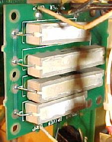
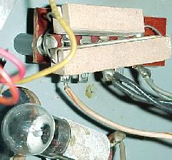
|
330 Ohm Pre-Heat Resistor Dropped from the Flash Lamp Circuit.
Starting with Big Guns/Space Station/Cyclone, the flash lamp resistors were moved
from under the playfield to the backbox. This isolated the resistors
from shock so they didn't break off the board. Then starting with Banzai Run,
an "interconnect board" was used to hold all the flash lamp resistors in the
backbox. At this time Williams also dropped
resistor R1 from the circuit and only used R2 on the interconnect board.
This greatly increased reliability because it seemed like resistor R1
(330 ohms 7 watts) was the resistor that broke the most.
I've repaired F-14 Tomcat games (this is prior to Big Guns)
where all the R1 (330 ohm 7 watt) power resistors
and some of the R2 (5 ohm 10 watt) resistors were broken on the
under-the-playfield resistor board. It was
quite stunning to fix these and have all the flashers work again!.
Interconnect Board Flash Lamp Resistors.
Starting with Banzai Run, the flash lamp resistors were moved
to the interconnect board. This kept the problem of vibration
to a minimum. But it did *not* solve the problem of the flash
lamp resistors breaking, disabling the flashers. The interconnect
board flash resistors can still get hot enough to desolder themselves
from the board, or have the resistor break from vibration.
Also the value of flash lamp resistors on the interconnect
board can vary from 3,4,5 or 11 ohms (depending on the number
of flasher bulbs being driven by a single transistor).
The wattage of the resistors decreased too, from 10 watt
to 5 watt on the interconnect board.
- 1 flasher: 11 ohm sand resistor
- 2 flashers: 5.6 ohm sand resistor
- 3 flashers: 4 ohm sand resistor
- 4 flashers: 3 ohm sand resistor
The interconnect board on a Banzai Run. These eight resistors can still have problems!
R1/R2 are 11 ohm, but the R3 to R8 resistors (8 ohms) often get hot enough to
desolder themselves from the board, or break from vibration. Of course the 330 ohm
warm-up resistors were removed from this circuit in the prior three games starting
with Big Guns, Space Station and Cyclone.
|
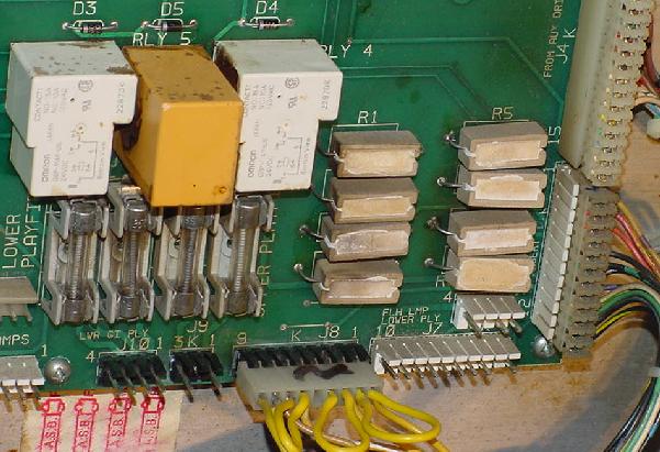
|
Norbert Snicer's drawing of the flash lamp circuit. V+ is the flash lamp
voltage. Note how R1 is a permanent path to ground for the lamp, through a
330 ohm resistor. This keeps the lamp "on" very slightly, until the
transistor on the left completes the path to ground thru 5 ohm resistor R2
(which will actually make the lamp "flash"). Remember current takes the
path of least resistance! This theory allows the lamp to flash very brightly,
but not burn out, because the lamp is "pre-warmed". Unfortunately this also
means the 330 ohm R2 resistor can get quite hot. Due to vibration and heat,
it is very common for the R2 resistor to fall off.
|
|
Why are there Low-Ohm Resistors in the Flash Lamp Circuit?
Williams used a 5, 7, or even 11 ohm five or ten watt resistors in the flash lamp
circuit. But why? The reason is simple, they were using 25 volts
to power a 12 volt #89 flash lamp bulb. The added resistor allowed
the higher voltage to be used without immediately burning out the
#89 flash bulb. This saved from having a separate 12 volt flash lamp
circuit (which they did design into the newer WPC board system).
Flashers on a High Speed playfield. The white 5 ohm resistors have
been replaced because the originals vibrated and desoldered themselves
from the board.
|
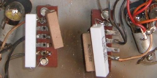
|
Flashers on a F-14 playfield. The board on the left has desoldered
the 5 ohm resistors.
|
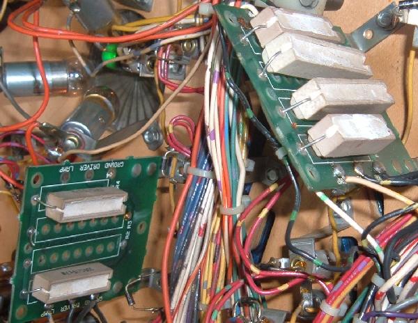
|
Flashers on a F-14 playfield. Here the broken resistors were replaced.
|
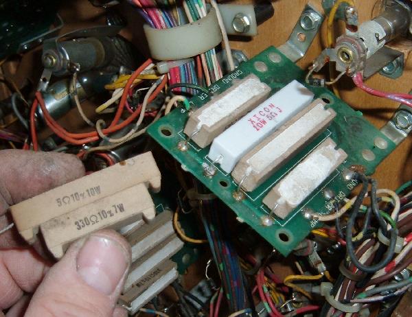
|
Flash Lamp Resistors Desoldering Themselves!
Another common flash lamp problem (for all system 11 games) has
to do with resistor R2 (usually 5 ohms 10 watt resistor).
These resistors can get so hot they actually
desolder themselves from the board! Always check these resistors
if you are having problems with your flash lamps.
Looking at the schematic above,
note how R1 is a permanent path to ground for the flash lamp, through a
330 ohm R1 resistor. This keeps the lamp "on" very slightly, until the
transistor on the driver board completes the path to ground thru 5 ohm resistor R2
(which will actually make the lamp "flash"). Remember current takes the
path of least resistance! This theory allows the lamp to flash very brightly,
but not burn out quickly, because the lamp is "pre-warmed". Unfortunately this also
means the 330 ohm R2 resistor can get quite hot. Due to vibration and heat,
it is very common for the R2 resistor to fall off.
Also the value of flash lamp resistors
can vary from 3,4,5,7 or 11 ohms (depending on the number
of flasher bulbs being driven by a single transistor).
Flash Lamps in Series.
On some games, multiple flash lamps were driven by the same driver
transistor, and were wired in series. This means if the "first"
bulb in the chain burns out, power will be cut to the second
flasher bulb. Keep this in mind when you see a pair of flashers that
are not working, which are next to each other. Flash lamps in series
do last longer though, because the overall power to the lamps is lower
(compared to wiring them in parallel).
1251 Flash Lamp Bulbs and 50 volt Flash Lamp Circuits.
On some system 11 games, Williams used a 1251 flash lamp bulb
instead of an 89 bulb. They did this because the 1251 flash lamp is
a higher voltage bulb. This allowed Williams to use a flash lamp
in a high power 50 volt solenoid circuit, instead of using
a #89 bulb in a 25 volt solenoid circuit. If your #89 flash lamps
are REALLY bright or constantly burning out, this may be a 50 volt
circuit and require a #1251 bulb.
You can measure the voltage at the lamp socket, using your
DMM set to DC volts, with the black lead on ground (metal side rails), and the red
lead on either lug of the flash lamp socket. But if this flash
lamp is on an solenoid A/C select circuit, you may have to
activate transistor Q7/Q8 (to switch between the A/C select circuit)
to get voltage at this socket (see the
transistor testing procedure above for details on this).
Flash Lamps Still Not Working - Tried Everything Else!
Remember flash lamps on most system11 games share a
driving transistor. The A/C relay kicks in to alternate
the power between a coil or a flash lamp. If the A/C relay
does not work (this can be tested in the game's solenoid test),
the flash lamps will never work. Instead the game will fire
a coil when it wants to fire a flash lamp. There's only a couple
games that don't use the A/C relay for flasher (High Speed
and Road Kings for example, which have flasher on their own
TIP transistors.)
With this in mind, there can other problems that cause
flash lamps to not work. For example, on games that have an interconnect
board (Banzai Run and later), in particular Jokerz and Space Station,
a failed optoisolator U1 (chip 4n25) on the interconnect board
can cause the flasher to not work. Normally this opto isolator
is used for the game to sense when the player
has pressed a fliper button (for lane change.) When this opto chip
senses coil voltage, it triggers a switch matrix switch. If the opto chip is bad,
the CPU board may not send data to the TIP transistor drivers when they are on "C"
side of the A/C relay (remember the "C" side is what direct power to the
flash lamps.) Interestingly the game will still drive the "A" side coils just fine.
To diagnose this problem, go to the switch edge diagnostic test.
Now press both flipper button (one at a time.) The display should
show the flipper lane change buttons as "closed" upon hitting either
flipper button. If this does not work, there is a problem with
the opto isolator on the interconnect board (4n25).
"A/C Secect Switch Error (Earthshaker and later).
On Earthshaker and maybe one or two other later system11 games,
switch#2 in the switch matrix is actually connected to a switch on the
A/C relay. So Earthshaker knows when the A/C relay closes.
If it doesn't see this switch#2 close, the flash lamps will
not work - that is the game will not send a signal to pulse
the TIP driving transistors for the flash lamps.
So bottom line if the A/C relay switch#2 does not close,
the CPU will not allow the flashers to work.
So if the A/C relay is broken (or the switch#2
which is part of the A/C relay does not close), none of the flash
lamps will work. This was probably done so if there was a problem
with the A/C relay, where the game would normally do a flasher "light show",
the game would fire off all the solenoids instead of the flasher.
If this switch doesn't close the CPU assumes the A/C relay is at
fault, and hence not pulse the flash lamps.
3L. When things don't work: the Lamp Matrix
Lights controlled by the CPU (not the General Illumination lights), are
controlled in a similar fashion as a switch matrix. That is, there
are eight lamp rows, and eight lamp columns. This gives a total of
64 CPU controllable lamps. These lamps are powered by +18 volts DC.
This voltage is strobed (turned on and off very quickly),
and hence the final power to the lamps is about 6 volts.
System 11 lamp matrix of 8 rows and 8 columns.
|
|
The lamp columns are controlled by TIP42 transistors that switch
the +18 volts on and off many times within a second. The lamp rows are controlled by TIP122/102
transistors that switch the ground on and off.
Because the TIP42's source the current (instead of sinking the ground
like a TIP122/102), lamp column TIP42 transistors go bad more often
than TIP122/102 lamp row transistors.
The most common CPU Controlled Lamp Problem.
The most common controlled lamp problem is if the fuse that connects
to the large 30,000 mfd capacitor in the backbox blows. If this happens, ALL the CPU
controlled lamps will not work! This fuse connects to this BIG capacitor
and a bridge rectifier right next to it. Check these components too for
a broken wire lug.
Overly Bright Lamps.
When a transistor or diode goes bad, generally it shorts on. If a transistor
shorts on in the lamp matrix, it will make all the
lamps in that row or column appear permanently on, and be very bright.
This happens because the
lamp matrix is actually +18 volts that is continually turned
on and off, a row or column at a time.
This nets a lower +6 volts that the lamps require.
The lamps are never allowed to get full brightness at +18 volts
before being switched off. If a transistor has
shorted on, a row or column of lamps will be turned on for a longer
time, and hence be brighter.
All the computer
controlled lamps in the lamp matrix should flash in attract mode,
or in the "All Lamps" diagnostic test.
If a number of lamps are just on (and they aren't general illumination lamps),
there may be a lamp matrix transistor problem.
If a number of lamps are out, check the bulbs and fuses first. If
a number of lamps are stuck on, check the game
manual and see if they are in the same row or column. If so,
you can test the individual transistor
(see the Testing Transistors and Coils section)
before replacing it.
Left: 44/47 lamp, socket and the orientation of the diode.
Note the banded end of the diode goes to the "middle" lamp lug.
The non-banded end goes to the lamp's tip lug.
Right: The playfield socket used for 555 lamps. The small metal
tabs on the outside of the socket often get bent. This prevents a
good connection to the board on which they plug. Bend them back
for better contact.
|
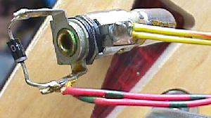
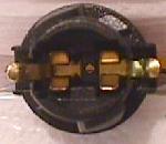
|
Left: the component (lamp) side of a lamp board. Note the diodes
mounted to the board, and the use of 555 bulbs.
Right: the solder (socket) side of a lamp board. Note the Molex
header pins soldered here. Often these Molex pin solder joints crack
or become fatigued, preventing the lamp(s) from working.
|
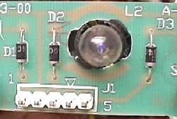
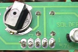
|
Testing a diode on a lamp socket circuit
board. The black lead is on the banded
side of the diode.
|
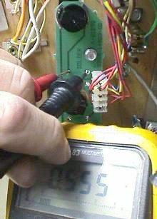
|
Lamp Diodes.
Each CPU controlled lamp will have a diode associated with it.
If this diode is bad (shorted on), it will cause other lamps
in that row or column (or even another row or column) to turn on.
You can usually see this in the "All Lamps Test".
The faulty row or column will light
TWICE in a single lamp matrix sweep (once when it should be on,
and a second time due to the short on ANOTHER row or column re-lighting it).
The lamp(s) in question are on twice as long as all the other CPU
controlled lamps.
If a lamp diode has broken (become open), or is disconnected
from the lamp socket, its lamp will not light.
Two Lamps On Instead of One.
If a lamp diode is shorted on (or installed incorrectly), this can cause
two lamps to act as one. This can be seen in the "Single Lamp Test".
Each individual lamp in the
lamp matrix (as displayed on the screen) should flash.
The "start game" button will move the test from one lamp to another.
If TWO lamps flash in this test instead of just one, suspect
this lamp has a bad or mis-installed lamp diode.
Testing a Lamp Diode.
In order to test a lamp diode, use your DMM set to diode test.
Turn the game off and put
the black test lead on the banded side of the diode. You should get
a reading of .4 to .6 volts.
Reverse the leads and put the red lead on the banded side of the diode.
You should get a null reading.
Any other reading and this lamp's 1N4004 diode should be replaced.
You don't have to remove the light bulb or desolder the diode
to perform this test. You can also test the diode soldered to the
circuit boards that hold the 555 lamps in the same manner.
Testing the lamp matrix columns using two test leads, a 555 socket
(pulled temporarily from the playfield), and a 1N4004 diode. One test lead
is attached to pin 1 of 1J6 on the CPU board, and is stationary. The other
end is attached to the light socket. Another test lead is connected to the
second lead of the lamp socket. A diode is clamped into the other end of the
test lead. Then the non-banded side of the diode is touched to each
pin of connector 1J7. The "all lamps" test should flash the lamp for each pin.
|
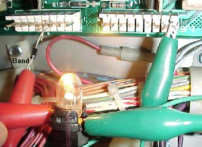
|
Testing the Lamp Columns.
If you suspect a TIP42 transistor that drives a lamp column as bad,
you can test it:
- Remove the backglass and fold down the display to gain access
to the CPU board.
- Unplug the connectors at 1J6 and 1J7 (lower right portion
of the CPU board).
- Turn the game on.
- After the game boots, press the center red button inside the
coin door into the down position. Then press the black button closest
to the coin door. Now press the center red button again. Pressing the
black button closest to the coin door will move from test to test.
- Go to the "All Lamps" diagnostic test.
- Connect your alligator test lead to pin 1 of 1J6. Pin 1 is the
right most pin, as facing the board.
- Connect the other end of this test lead to one lead of a 555 light socket.
You can temporarily get one of these from a playfield lamp
(make sure it's a working lamp first!).
- Connect another test lead to the second lead of the 555 light socket.
- On the other end of the test lead, clip on a 1N4004 diode,
with the non-banded end away from the alligator lead. Touch the non-banded end
of the diode to pin 1 of 1J7 (the columns plug).
Again, pin 1 is the right most pin, as facing the board.
- The lamp should flash.
- Move the diode/alligator lead on 1J7 to the next pin. Again, the lamp
should flash.
- Repeat the previous step, until the last pin of 1J7 is reached.
If a lamp column tested doesn't give a flashing test lamp, that column
is bad (or you have the test diode reversed!).
No light or a non-flashing, bright lamp are signs that the
respective TIP42 column transistor is bad. Test the transistor as described
in Testing Transistors and Coils.
Testing the lamp matrix rows using two test leads, a 555 socket
(pulled temporarily from the playfield), and a 1N4004 diode. One test lead
is attached to pin 1 of 1J7 on the CPU board, and is stationary. The other
end is attached to the light socket. Another test lead is connected to the
second lead of the lamp socket. A diode is clamped into the other end of
the test lead. Then the banded side of the diode is touched to each
pin of connector 1J6. The "all lamp test" should flash the lamp for each pin.
|
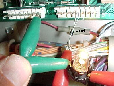
|
Testing the Lamp Rows.
If you suspect a TIP122/102 transistor that drives a lamp row as bad,
you can test it:
- Remove the backglass and fold down the display, to gain access
to the CPU board.
- Turn the game on.
- After the game boots, press the center red button inside the
coin door into the down position. Then press the black button closest
to the coin door. Now press the center red button again. Pressing the
black button closest to the coin door will move from test to test.
- Go to the "All Lamps" diagnostic test.
- Unplug the connectors at 1J6 and 1J7 (lower right portion
of the CPU board).
- Connect your alligator test lead to pin 1 of 1J7. Pin 1 is the
right most pin, as facing the board.
- Connect the other end of this test lead to one lead of a 555 light socket.
You can temporarily get one of these from a playfield lamp
(make sure the lamp works first!).
- Connect another test lead to the second lead of the 555 light socket.
- On the other end of the test lead, clip on a 1N4004 diode,
with the banded end away from the alligator lead. Touch the banded end
of the diode to pin 1 of 1J6.
Again, pin 1 is the right most pin, as facing the board.
- The lamp should flash.
- Move the diode/alligator lead on 1J6 to the next pin. Again, the lamp
should flash.
- Repeat the previous step, until the last pin of 1J6 is reached.
If a lamp row tested doesn't give a flashing test lamp, that row
is bad (or you have the test diode reversed!).
No light or a non-flashing, bright lamp are signs that the
respective row TIP122/102 transistor is bad. Test the transistor as described
in Testing Transistors and Coils.
Testing the Lamp Rows; Another Way.
The lamp rows are controlled by TIP122/102 transistor at Q80 to Q87.
With the game in diagnostics test mode (sound test is find),
run an alligator jumper wire from ground to the metal tab
on one of these TIP122/102 transistors. This will cause the entire lamp row to
light up.
The Lamp Matrix Power Resistors.
On the CPU board at the lower right corner, there
are eight .4 ohm, 3 watt wire wound sand resistors (R113, R116, R119, R122, R125, R128,
R131, R134). Sometimes these resistors get hot and de-solder themselves from
the CPU board and fall off (or the solder joints need re-soldered).
If you are having lamp matrix problems and it's not the row or column
transistors, make sure you check the resistors too.
Most Common Problems with Lamps.
- Bad bulb. Any light bulb can burn out. Often you can visually see
the bulb is burnt, but sometimes you can't. Test the bulb with your DMM,
set to continuity. Put your test leads on the bulb. No continuity,
and the bulb is bad.
- Wire broken away from the socket. This happens quite often and
requires re-soldering the wire back to the socket lug.
- Diode broken away from the socket. If the lamp diode becomes
disconnected from its socket, the lamp will not light.
- Corroded or Bad Socket. Games imported back into the US from other countries
exhibit this problem more often. Re-seating the bulb in its socket
often fixes this problem.
On 555 plug-in sockets, bend the contact tabs slightly for better contact.
- Blown Fuse. If several GI lights don't work, check the fuse associated
with them. If all the CPU controlled lamps don't work, check the fuse by
the BIG 30,000 mfd capacitor and bridge bolted to the back of the backbox.
- Burned Connector on the power supply or interconnect board. This happens most often with
GI (general illumination) lamps. See Burnt GI Connectors
for more info.
- Lamp matrix power resistors. On the CPU board, lower right corner, there
are eight .4 ohm, 3 watt wire wound sand resistors (R113, R116, R119, R122, R125, R128,
R131, R134). Sometimes these resistors get hot and de-solder themselves from
the CPU board and fall off (or the solder joints need re-soldered).
- Bad Column Transistor. The TIP42 transistors that control the lamp matrix
columns often fail. If this is the case, all the lamps in a particular column
will be brightly locked on.
- Two Lamps act as One. If a lamp diode has a shorted on, this can
cause two different lamps to act as one.
I replaced the Offending TIP122 and TIP42, and I've check the Lamp
Matrix Power Resistors, but the Lamp Matrix still
doesn't Work Right.
It is rare, but problems in the lamp matrix can occur further up stream.
For the lamp matrix columns,
transistors Q51, Q53, Q55, Q57, Q59, Q61, Q63, Q65 are 2N6427 transistors
which drive the TIP42 column transistors. Sometimes these can fail too.
And before the 2N6427 transistors are two 7408 TTL chips at U52 and U53
which drive the whole circuit. These all connect to the
6821 PIA at U54. Any of these components can fail too.
For the lamp matrix rows,
7406 TTL chips at U55 and U56 drive the rows though a series of 2N5060
(NTE5400) silicone controlled rectifiers at S1-S8. These also connect to the
6821 PIA at U54.
End of System 11 Repair document Part Two.
* Go to System 11 Repair document Part One
* Go to System 11 Repair document Part Three
* Go to the Pin Fix-It Index at http://pinrepair.com
|
