3k. When things don't work: the Switch Matrix
Switches on any pinball game are very important. On electronic games, when a switch closes,
it informs the CPU to score points, award a feature, and/or to activate a solenoid.
If a switch is stuck closed, the CPU will ignore this switch
(in most cases).
If a switch is not activated in a number of games, or is permanently closed, the
switch is assumed to be bad. This will create a test
report, which is shown when the game is turned on (implemented well
in system11b, prior to this not implement as well).
If a particular feature of a game is difficult to score,
it's associated switch may be (falsely) assumed bad (if not activated
in several games). To correct the test report, remove the playfield glass,
and activate the switch by hand within a game, or within the diagnostics
switch edge test.
All switches on a system 11 game (except for the direct switches at
connector 1J14 which
are only the test button switches, and the six special solenoid switches at 1J18)
are in the "switch matrix".
The switch matrix is controlled by eight switch columns, and
eight switch rows. The cross-section of any row and column designates any
one of the potential 64 different switches. The switch columns are controlled through
CPU board connector 1J8, which connects to
2N3904 transistors Q42-Q49. The output of these goes to a 74LS244 chip on the CPU board at U40.
The output of this chip then goes to a 6821 PIA at U38. The switch rows are controlled through
CPU board connector 1J10, which connects to 4011 chips at U30 and U39 (or U51/U52 respectively
on system9), where U30 (U51 on s9) are rows 1-4 and U39 (or U52 on s9) are rows 5-8. This then
connects to the same 6821 PIA at U38. Note early System11 CPU boards also have a
switch row connector at 1J9 that was to be used for opto switches, but this
connector was removed by System11a and was never implemented on any game.
Test Button Switches.
On system 11 games, the test button switches inside the coin door only are wired directly
to the CPU board at connector 1J14. These switches do not go through the switch
matrix on any system 11 revision. The test button switches are
direct switches to the CPU board, which directly to the CPU. The diagnostic
switch connects to the CPU's NMI line. Williams did this so if there is
a switch matrix short, you can still get into the game's diagnostic
tests without using any switches in the switch maxtrix.
Shorting the Switch Matrix to +50 volts.
When in a hurry, many make an under playfield adjustment
with the game turned on. Doing a switch adjustment with the power on
could easily short a coil lead (+25/50 volts) to a switch lead.
This will immediately blow the switch matrix, and can fry
most anything up to and including the 6821 PIA at U38.
Start with the switch column connector 1J8 which goes to eight
2N3904 transistors Q42-Q49, as these are first
inline (and test easily with a DMM set to diode test).
Often that is all that gets damaged, but it can go further.
The output of the 2n3904's goes to a 74LS244 chip on the CPU board at U40.
And the output of this chip then goes to a 6821 PIA at U38.
Depending on what switch contact was shorted to coil power, if the switch
matrix still does not work, check the
switch row logic path. The switch rows are controlled through
CPU board connector 1J10, which connects to 4011 chips at U30 and U39 (or U51/U52 respectively
on system9), where U30 (U51 on sys9) are rows 1-4 and U39 (or U52 on s9) are rows 5-8. This then
connects to the same 6821 PIA at U38.
If after replacing the suspect components,
disconnect the switch input plugs from 1J8 and 1J10 at
the bottom of the CPU board. Put the game into switch
test mode, and none of the switches should be activated!
If a whole row of switches is activated, that would mean
that something in the row chain is still bad.
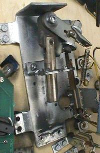
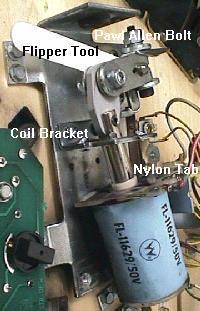
Shorting the Flipper EOS switch to the Lane Change switch.
Williams has a feature called "lane change" in many of their games.
This allows the player to change the lit lanes using the cabinet flipper
buttons. Prior to Banzai Run, this is done by doubling up a second switch on the flipper
EOS switches. The EOS switches are a +50 volt switch. The lane change switch is a
+5 logic switch connected to the switch matrix. These two switches are
insulated from each other by a small nylon "triangle" activator. But if
these two switches touch, the switch matrix will burn (as
described above).
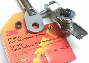
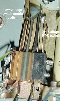
Games Cyclone and before: the EOS flipper switch
on these games is actually two switches. The switch
on the left (with the diode) is low-voltage and connected
to the switch matrix. This normally open switch closes
when the flipper is activated, and controls the lane
change and high score initials. The switch on the right
is the high-voltage flipper EOS switch. A nylon space
insulates the two switches from each other.
|
|
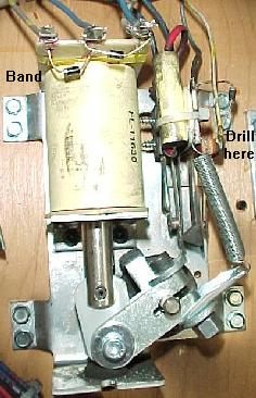
When adjusting or cleaning the flipper EOS switches or lane change switches,
make sure the game is turned OFF. This will prevent shorting these
two switches together. Also, do not clean the smaller lane change switch
with anything other than a business card.
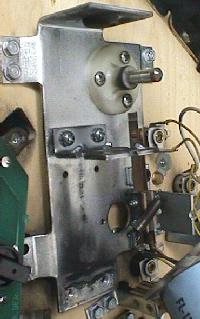
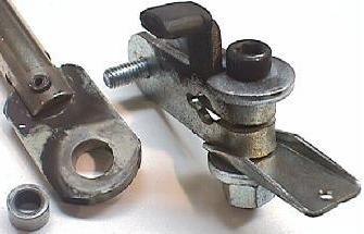
Banzai Run, Swords of Fury style lane change switch.
Instead of having the lane change switch matrix switch on the
EOS switch stack, these games used a micro-switch on the
cabinet flipper buttons.
|
|
Lane Change on games with Interconnect boards.
When the interconnect board was introduced on Banzai Run, Williams stopped
using a doubled up switch on the flipper EOS switches for the lane change.
Instead they moved the lane change switches to the flipper cabinet
switches using micro-switches. This was done at least up to Swords of
Fury (sys11b). Then Williams made a change to the interconnect board.
Circuitry was added on the interconnect board for Taxi using a MOC3010
optoisolator/triac output chip (NTE3047).
Just a game later (Jokerz), Williams changed to
the 4N25 opto isolator/NPN transistor output chip (NTE3040).
If having problems with the lane change on these games, replacing
the small opto isolator chip will usually fix the problem
(assuming it's a system11B or later game).
Also check the interconnect board's connectors
for burnt pins and burnt traces on the 50 volt solenoid voltage
lines. It is very common for a burnt connector or burnt traces on the board
to not allow the optoisolators to work, preventing lane change.
Switch Numbering.
Each switch has a number associated with it. Unlike WPC, system 11
switches are just numbered 1 to 64. There is no relationship to
what row or column number the switch number is (on WPC, switch 43
is column 4 row 3, for example). On system 11 games, switches 1 to 8
are column 1, rows 1 to 8. Likewise, switches 9 to 16 are column 2,
rows 1 to 8. This continues up to switches 57 to 64, which are
column 8, rows 1 to 8.
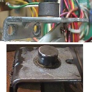
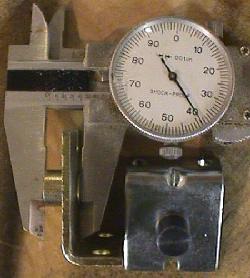
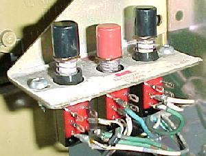
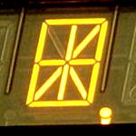
To enter diagnostics, the red center button must be
in the "down" position (as shown here). If the center
button is "up", you will enter the audits menu instead.
|
|
Using the Internal Switch Tests.
To test switches, use the internal test software. Press the center red
button inside the coin door down, then press the black button closest
to the coin door. Finally, press the center button again. The button
closest to the coin door will take you from test to test. Go to the
"switch level" test and
activate any switch on the playfield using a pinball (this simulates
real game play), and it should show on the
game's display.
If a Bad Switch is Found.
If a switch does not work, check these things:
- On the top side of the playfield, make sure the bad switch contacts
haven't been bashed together by an errant air pinball.
- If it's a micro-switch, check the actuator arm. Make sure it's
adjusted properly. Listen for the micro-switch's "click" when activating. No
click usually means the switch is mis-adjusted or broken.
- Check that the wires going to the switch are soldered well, and haven't
fallen off.
- Check the continuity (using your DMM's continuity setting) of the wire
between this switch and another working switch in the same column (white wire)
or row (green wire).
- If it's a blade or leaf style switch, check the contacts for proper
closure. Clean the switch contacts with a business card (do NOT use a file
as the contacts are gold plated). Put the card between the contacts, close
the contacts, and pull the card through the contacts. This is all that is
needed to clean gold plated switch contacts.
- Check the switch to make sure it works. Use your DMM's continuity
setting, and put one lead on the "common" lug (the lug to which the banded
end of the diode connects) of the switch. Put the other lead on the green
(normally open) switch lug. Your meter should only beep when the switch is activated,
and not beep when the switch is de-activated. Move the DMM's lead from the green to
the white wire (normally closed) switch lug. Your meter should beep when the
switch is de-activated, and NOT beep when activated.
- Check the diode on the switch. Make sure the diode is connected properly,
and is working (see below).
- Check other switches in that switch's row
or column. Two 4041 chips control rows, and 2N3904 transistors and 74LS244 at U40
control columns. Both rows and columns are controlled by a 6821 PIA at U38.
If the switch is bad, replace it. If all the switches are bad in a particular
switch column or row, start replacing components closest to the switch.
System 11 switch matrix of 64 switches: eight rows and eight columns.
|
|
Random/Phantom Switch Closures: a Shorted Switch.
-Or- One Switch Activates Multiple Switches.
-Or- Many Switches Activiate the Same Switch.
It's a strange problem. You're playing a game, and when the ball
goes down the right inlane, the left slingshot fires! Or when you
make a ramp shot, the game slam tilts. One switch closes, but a
completely unrelated event than occurs. Or whenever going into the
switch edge test, most of the switches came up as the same switch!
This is a classic problem of a shorted switch. It confuses the
switch matrix into thinking something else has occurred. This
can happen from an "air" pinball, that bashes an above playfield
switch's contacts together, causing a short. Also a bad switch diode
can do this too. In either case, you need to find the shorted
switch. Unfortunately, it won't be obvious. The switch
matrix is confused, so any diagnostics the game provides will
be of limited help.
First, try and find the switch that causes something unrelated ("phantom")
to happen. Take the playfield glass off, and start a game.
Activate the switches with your hand, and find the switch which activates
the phantom (unrelated) switch.
Once you have found the switch, go to the game manual and find
the switch's number, row number, and column number. Say for example,
switch 53 (column 7, row 5) is causing the phantom closure. Now you
need to get the other three switches that make up the "square" of this
row and column. First get the reverse switch number, switch 39 (column 5, row 7).
Then get the other two switches: switch 37 (column 5, row 5), and
switch 55 (column 7, row 7). Your switch short will probably be one of
these four switches.
For example, a reading was having a problem on his Road Kings where
the game tilted randomly. The problem was narrowed down to the right
slingshot; when it fired the game would occassionally tilt.
It turned out the slingshot switch was just barely
shorting with the Y-Ramp through switch. The problem was not
reproducable in the switch tests, but only with the playfield down
during game play.
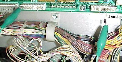
If you are having problems figuring out if the short is in the playfield
or the CPU board, try this. Put the game in switch edge test.
Remove connectors 1J10 and 1J8 from the CPU board. Using the manual,
find which row and column of the switch that is causing the phantom closure.
Then cross this row and column directly on the CPU board (with an alligator clip,
as described below in the "testing the switch columns/rows").
The row and column numbers for each pin of connectors
1J10 and 1J8 are listed below. If the phantom switch does not activate, the problem is
in the playfield. If the phantom closure still works, you have a CPU board problem.
If your phantom switch problem is on the CPU board, don't forget to look
at the resistor networks SR9, SR10 or SR11 on the CPU board. If one of these resistor
networks goes bad, it can cause weird switch behavior.
It can be tested with a ohm meter, but since the resistor networks are
"in circuit", the test is not necessarily conclusive depending on
which SIP network is involved (see below for more details on
this). Note F-14 Tomcat seems to *really* have problems with these
resistor networks.
More Strange Switch Closures: the Switch Matrix Resistor Networks.
The resistor networks in the switch matrix can fail, and this is weird
problem. This can cause random switch closures and generally
strange switch behavior like random scoring, random tilting, or even
the slam switch randomly activating. The only solution is to test
and replace the resistor networks involved.
There are two types of resistor networks (SIP) used on the system 11
CPU board; "Bussed" and "Isolated" (aka Discrete).
If a resistor network is "560 x 9R" and has 10 pins, that means it's BUSSED;
there are nine resistors, and they are all tied to one common pin
(this pin is labeled with a white square around it on the circuit board).
These can be tested out-of-circuit with a DMM set to ohms. Just put one
lead on the "dot" leg of the SIP, and test the other nine legs one at a
time. The same resistor value should be seen.
If a resistor network is "1K x 4R" and has 8 pins, this is an ISOLATED or DISCRETE resistor
network; there are four resistors in the same small package, and uses two
pins per resistor. Each pair of pins are a separate resistor. To test
out-of-circuit, put the two
DMM leads on a pair of pins to get the resistor ohm value.
Information on how to test the SIP resistor networks in-circuit is listed below.
|
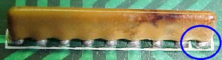
Left: A bussed resistor network.
Right: An isolated (discrete) resistor network.
|
|
Here are the different resistor networks used in the system 11 switch matrix (listed in
general order of failure):
- SR9/SR10* = 1k ohms x 4 resistors isolated/discrete (8 pins).
Used for the switch returns (rows). Mouser part# 652-4608X-102-1K.
Easy to test in-circuit.
- SR11* = 560 ohm x 9 resistors bussed (10 pins).
Used for the switch returns (rows). Mouser part# 652-4310R-101-560.
Easy to test in-circuit.
- SR3/SR15/SR17* = 4.7k ohms x 9 resistors bussed (10 pins).
Used for the switch drives (columns).
Mouser part# 652-4310R-101-472.
- SRC6* (1k/470 pfd) = resistor/capacitor network for switch matrix columns.
Has 1k ohm resistors with 470 pF caps in a single package.
Can not be tested in-circuit. Replace with a 1k ohm x 9 resistor bussed (10 pins) with
no capacitors. Cut off pin 10 (important!), and install pin 1 (common) in pin 1 of the board.
The cut pin 10 of the resistor network does not go into the board's pin 10 position. See notes
below for more info on this. Mouser part# 652-4610X-1LF-1K.
- SR14 = 3.3K ohm x 9 resistors (10 pins) bussed.
Used for the opto switch returns (rows). Not used in any game
for switches directly, but if this SIP is bad will cause switch matrix row problems.
Mouser part# 652-4310R-101-3.3K. Easy to test in-circuit.
- SR8 = 1k ohm x 9 resistors bussed (10 pins). Mouser part# 652-4610X-1LF-1K.
* Most commonly failed resistor networks in system11 boards.
All these Bourns resistor networks (except for the SRC6) can be ordered from
mouser.com or
greatplainselectronics.com.
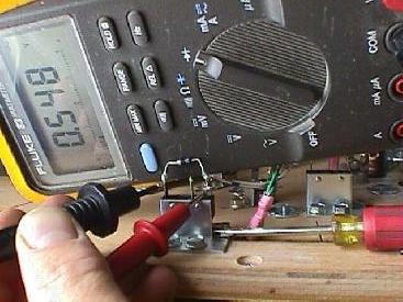
When testing a BUSSED resistor network, first find pin 1. This pin
will have a white square around it, to isolated it from the rest of the
pins. Use a DMM set to ohms, and put one lead on pin 1. Put the other
lead on each pin 2 and up. The same reading should be seen for each pin 2 and up.
Note "in circuit" (resistor network installed in the board) some networks may have
pins that measure differently than the other pins (for example, pin 10 of SR17 which
measures about half what the other pins measure).
Out of circuit (resistor network not installed in the board)
all pins should measure the same.
When testing an ISOLATED (discrete) resistor network, put the DMM leads on the two adjacent
pins furthest to the right or left, and note the reading. Then move both DMM leads
down two pins. The same value should be seen. Continue down the resistor, moving
both DMM leads two pins at a time, until all adjacent pins are tested.
Again note "in circuit" (resistor network installed in the board) some pins may
measure differently than the actual value. Out of circuit (resistor network not
installed in the board) all pins should measure the same.
Note: Testing resistors/capacitor networks "in circuit" is
may not be conclusive. A bad resistor network which is soldered into the
circuit board can test as "good", but in fact be bad. This does
happen (but pretty rare). My advice is this: if the resistor network tests "strange"
(as shown below), probably best to replace it. Note SR9, SR10 and SR11 are
the most commonly failed resistor networks in system11 CPU boards
(but luckily these are easy to test in-circuit). The SRC resistor/cap
SIPs are a bit more tricky to measure in-circuit.
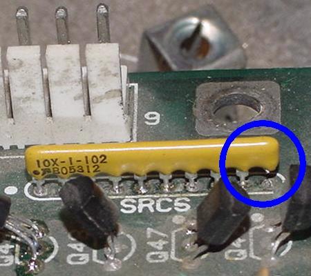
A bussed resistor network on a DataEast game. Note the white
square around pin 1; this is the common pin. DataEast's CPU
is basically a clone of system 11, except they use 9 pin
resistor networks.
|
|
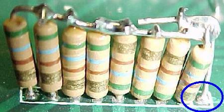
A "hacked" bussed resistor network (same DataEast CPU board as above).
If the correct resistor network can not be found, this shows how to
make a bussed resistor network from individual resistors. Note the
white square around pin 1; this is the common pin. This picture shows
quite well how a bussed resistor network is wired. Since some resistor
networks are hard to get, this repair will get more and more common.
|
|
Thankfully Williams used even pin number resistor networks
(unlike DataEast's CPU board, which is essentially a clone of
Williams' System 11 CPU board). The even pin
numbered devices are far easier to find than the odd pinned ones.
Resistor/Capacitor Network (SRC6).
On the CPU board at SRC6 there is also a resistor/capacitor network.
This is similar to the resistor networks
described above, but there are also capacitors inside the network, in addition
to the resistors. This Resistor/Capacitor network at SRC6 was removed
on System11b CPU boards and made into descrete resistors and capacitors.
But on earlier Williams CPU boards,
these SRC packs have eight resistors (1k or 4.7k ohms) and eight capacitors (470 pfd),
in a ten pin SIP package. Pin one of the network is tied to +5 volts and
connected to the eight resistors. Pin ten of the network is tied to ground
and connected to the eight capacitors.
These are a real bear to find, but they are made by
BI Technologies, their part series CR10-S with 4.7k ohm
resistor and 470 pfd capacitor. Unfortunately I can't find anyone
that has these in stock without ordering 5000 of them!
So just use a 1k resistor (1k x 9r) bussed SIP network without the capacitor.
That will work fine for SRC6.
Here's a run down of what these SRC networks are used for:
- SRC6 (1k/470 pfd) = switch matrix columns.
- SRC2,SRC4,SRC5 (4.7k/470 pfd)= score display data.
- SRC7,SRC8 (4.7k/470 pfd)= score display digit strobes.
- SRC9 (4.7k/470 pfd) = score display BCD.
- SRC1,SRC3 (4.7k/470 pfd)= "widget I/O" (the sound board).
Note that these SRC networks can not be tested "in circuit".
That is, they have to be removed from the board to get a good
test. Usually the resistance part of the SRC shows less than
the value stated for the SRC (.6 to 2.2k ohms, versus 4.7k ohms).
In order to test them they need to be removed from the circuit board.
Installing a SR instead of a SRC at SRC6.
In the case of SRC6 (switch matrix columns),
if the original SRC resistor/capacitor network can not be found,
it can be replaced with a straight SR resistor network (with no capacitor).
This may also work with the SRC1-SCR5 and SRC7-SRC9.
If this is done, a "1k x 9R" bussed resistor network can be used. But it
must be installed correctly! This bussed resistor network will have
ten pins, with one "common" pin (the pin with the "dot"). The common pin 1
of the resistor network must go in the board's pin 1 (for +5 volts).
BUT the last pin 10 of the resistor network should be cut and not installed
in the CPU board, because this pin on the CPU board goes to ground
(for the capacitor part of the SRC, which we are not using since
we're installing a SR and not a SRC). Using a SR instead of a SRC
works because Williams installed some optional capacitors at
C49-C56 (.01uF). If replacing SRC6 with a straight resistor network,
caps C49-C56 should be installed. In most cases these are installed
from the factory, but it's best to double check.
Again, to repeat, if using a SR resistor only network instead of a
SRC resistor/capacitor network, the last pin (pin 10) of the SR
should be modified for use in the
system11 CPU board. Just cut off the last pin (pin 10) on the resistor network opposite
the "common" pin. Remember the common pin
is the pin with the "dot", so cut off the 10th leg furthest away
from the dot.
Installing a SR in place of a SRC at SRC6 for the switch matrix
columns. Note pin 10 of the SR bussed SIP network is cut.
|
|
Bad Switch Diode.
Each micro-switch on the playfield also has an 1N4004 diode soldered to
it. This diode can short closed. It doesn't happen often though.
Important: If a switch diode does short closed,
all switches in that particular column or row
will exhibit strange behavior. If a switch diode goes permanently open,
the switch will never register. Keep this in mind when diagnosing switch matrix
problems.
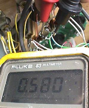
Fail-Safe Diode Test.
With the game off,
use your DMM set to diode position. With the black lead on the banded
side of the diode, you should get a .4 to .6 volt reading. Reverse the leads,
and get a null reading. If the diode test bad,
cut one lead of the diode from the switch to remove it from the circuit,
and test it again just to make sure the diode is really bad.
Reconnect the diode after testing, or replace it if bad.
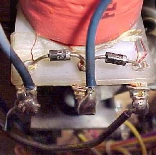
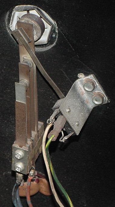
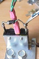
Testing a switch diode on a microswitch without removing the
diode. Not the screw driver keeps the switch activated, and the
middle green wire (ground) has been disconnected.
|
|
Testing a Microswitch's Diode, without removal.
You can test the diode on a microswitch without unsoldering a diode lead from
the switch. This technique assumes the switch is wired in the standard
configuration: green (ground)
wire to the center lug, the banded end of the diode to the far switch lug, and the
non-banded diode lead and the switch wire(s) to the close switch lug (as shown
in the pictures above).
- Disconnect the middle green (ground) wire from the switch. It should
have a quick connector. If the middle green ground wire is
soldered to the switch, ignore this test and
do the above "fail-safe" diode test.
- Put your DMM on diode setting.
- Connect the black lead of your DMM to the diode's banded side,
and the red lead to the non-banded side.
- Activate the switch.
- You should get a reading of .4 to .6 on the meter.
- Reverse the DMM's leads (red lead to the diode's banded side),
and keep the switch activated. You should get a null meter reading.
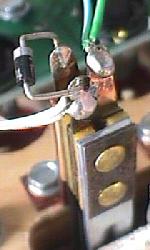
Testing a Blade/Leaf Switch's Diode.
Testing the diode on a leaf switch is far easier.
No wires need to be disconnected, and the switch should not
be activated. This technique assumes the switch is wired in the standard
configuration: green (ground)
wire to the center lug, the banded end of the diode solo, and the
non-banded diode lead and the switch wire(s) to the other switch lug (as shown
in the pictures below).
- Leave the leaf switch's diode and all wires connected.
- Make sure the switch isn't activated.
- Put your DMM on diode setting.
- Connect the black lead of your DMM to the diode's banded side,
and the red lead to the non-banded side.
- You should get a reading of .4 to .6 on the meter.
- Reverse the DMM's leads (red lead to the diode's banded side).
You should get a null meter reading.
Testing a switch diode on a blade/leaf switch, without
removing the diode. The switch doesn't need to be
activated, and no wires need to be disconnected.
|
|
Installing a New Switch Diode.
You can replace the diode with a 1N4004 (or 1N4002 or 1N4001)
diode. Make sure you install the new diode with its band in the same orientation
as the old diode (assuming it's correct!). If you're unsure, compare
the diode's band orientation to a working switch and diode. Most (but not all!)
switches have the green (ground) leads connected to the center (normally
open) lead of the switch. Then the row (white) wire is connected
to the switch lead closest to the center lead (the normally closed lead).
The banded end of the diode is connected solo to the far (common) switch leg,
and the non-banded end is connected to the same leg as the row (white) wire.
There are some exceptions to this mounting. Your game manual will specify
any non-standard switch installations.
Notice the orientation of the diode's band on these switches.
On a micro-switch, the ground (green) wire usually goes to the center
lug, the "live" wire and the non-banded side of the diode to the lug
closest to the center. The band on the diode goes to the solo,
far third switch lug. The leaf switch uses the same connection method
(ground to center, banded end of diode solo). Note there are some
exceptions to this mounting.
|
|
Switch Matrix Row or Column Problem: the Easy Test.
If you are getting an error message that you have a switch matrix
row or column problem, you need to determine if this is a CPU board problem
or a playfield problem. The easiest way to do this is to enter
the game's switch LEVEL diagnostics (coin door center red button down, press the black
button closest to the coin door), then unplug
the switch matrix row and column plugs at 1J10 and 1J8. If
the row or column problem is gone (no switch reports), you have a problem in the
playfield wiring. If the problem is still there, you may have a problem
on the CPU board. Note most shorted switch matrix column problems are caused by
a bad switch matrix column 2N3904 transistor at Q42-Q49 (which affects the
entire column).
Switch Matrix Plug and Pin Numbers.
If you are doing intensive switch matrix diagnostics with the
plugs removed at 1J10 and 1J8, you may want to simulate an actual
playfield switch closure, without using the playfield! This can
be done by using the internal switch edge test, and an alligator
lead connected to the particular row/column (switch) in question.
1J8 Switch Column Pin Numbers
- Pin 1 = Column 1, green/brown
- Pin 2 = Column 2, green/red
- Pin 3 = Column 3, green/orange
- Pin 4 = Column 4, green/yellow
- Pin 5 = Column 5, green/black
- Pin 6 = key
- Pin 7 = Column 6, green/blue
- Pin 8 = Column 7, green/violet
- Pin 9 = Column 8, green/gray
1J10 Switch Row Pin Numbers
- Pin 1 = Row 8, white/gray
- Pin 2 = Row 7, white/violet
- Pin 3 = Row 6, white/blue
- Pin 4 = key
- Pin 5 = Row 5, white/green
- Pin 6 = Row 4, white/yellow
- Pin 7 = Row 3, white/orange
- Pin 8 = Row 2, white/red
- Pin 9 = Row 1, white/brown
Testing the switch matrix columns: The diode is optional, but
here it is shown using a diode and a test lead. The test lead is attached
to pin 9 of 1J10, and is stationary. The other clip holds the non-banded
side of the diode. Then the banded side of the diode is touched to
each pin of connector 1J8. The "switch edge" test should indicate switches
1, 9, 17, 25, 33, 41, 49, 57 when moved from pin 1 to 9, respectively.
|
|
Testing the Switch Columns (all system 11 revisions).
To test the switch columns, do the following:
- Remove the backglass and fold down the display to gain access
to the CPU board.
- Turn the game on.
- After the game boots, go to the
Test menu's "Switch EDGE" test.
- Unplug the connectors at 1J8 and 1J10 (bottom portion
of the CPU board).
- Connect your alligator test lead to pin 9 of 1J10. Pin 9 is the
left most pin, as facing the board.
- Optional Diode: On the other end of the alligator test lead, clip on a 1N4004 diode,
with the banded end away from the alligator lead. Touch the banded end
of the diode to 1J8 pin 1. If not using the diode, just touch the other
end of the alligator clip to 1J8 pin 1.
Again, pin 1 is the right most pin, as facing the board.
- The display should show switch 1 is closed.
- Move the diode/alligator lead on 1J8 to the next pin. The display should
show switch 9 is closed.
- Repeat the previous step, until pin 9 of 1J8. Switches 1, 9, 17, 25, 33, 41, 49, 57
should be closed on the display as you move forward, pin 1 to pin 9, on
connector 1J8. Note pin 6 is a key pin, and should be skipped.
If a particular switch number does not display as closed, or is closed without
any test lead connection, or multiple switches close for single
connector pin test, there is a problem on the CPU board. Usually this
is a bad switch matrix column 2N3904 transistor at Q42-Q49.
Testing the switch matrix rows: Using the diode is optional.
The test lead is attached to pin 1 of 1J8, and is stationary. The
other clip holds the banded side of the diode. Then the non-banded
side of the diode is touched to each pin of connector 1J10. The
"switch levels" test should indicate switches 1, 2, 3, 4, 5, 6, 7, 8
when activated.
|
|
Testing the Switch Rows (all system 11 revisions).
To test the switch rows, do the following:
- Remove the backglass and fold down the display to gain access
to the CPU board.
- Turn the game on.
- After the game boots, go to the
Test menu's "Switch EDGE" test.
- Unplug the connectors at 1J8 and 1J10 (bottom portion
of the CPU board).
- Connect your alligator test lead to pin 1 of 1J8. Pin 1 is the
right most pin, as facing the board.
- Optional diode: On the other end of the alligator test lead, clip on a 1N4004 diode,
with the banded end towards the alligator lead. Touch the non-banded end
of the diode to 1J10 pin 1. If not using a diode just touch the other
end of the alligator clip to 1J10 pin 1.
Again, pin 1 is the right most pin, as facing the board.
- The display should show switch 1 is closed.
- Move the diode/alligator lead on 1J10 to the next pin. The display should
show switch 2 is closed.
- Repeat the previous step, until pin 9 of 1J10. Switches 1, 2, 3, 4, 5, 6, 7, 8
should be closed on the display as you move forward, pin 1 to pin 9, on
connector 1J10. Note pin 4 is a key pin, and should be skipped.
If a particular switch number does not display as closed, or is closed without
any test lead connection, or multiple switches close for single
connector pin test, there is a problem on the CPU board. Usually this
there is a problem with the CPU board.
Testing the Switch Matrix Columns and Rows with a Logic Probe.
If you have a logic probe, you can use this to easily test the switch
matrix:
- Remove the backglass and fold down the display to gain access
to the CPU board.
- Turn the game on.
- After the game boots, go to the
Test menu's "Switch EDGE" test.
- Unplug the connectors at 1J8 and 1J10 (bottom portion
of the CPU board).
- With your logic probe connected to power and ground,
probe each pin 1 to pin 9 of 1J8 (pin 1 is the
right most pin, as facing the board). These are the switch columns.
All pins should show PULSE on the logic probe.
- With your logic probe connected to power and ground,
probe each pin 1 to pin 9 of 1J10 (pin 1 is the
left most pin, as facing the board). These are the switch rows.
All pins should show HIGH on the logic probe.
If you don't get the following pulses or highs with the
logic probe, there is definately a CPU board problem. See below.
Bad Switch Column: How to Fix it.
Usually the switch column transistors fail here. These are 2N3904 transistors
at Q42 to Q49. See the Checking Transistors
section for details on testing these transistors. Right before the transistors
there is a capacitor network; this rarely fails (and is not documented
in the list below). Next each one of the
eight transistors connects to a 1.5k resistor at R71 to R78. Then the
resistors at R71 to R78 connect to a resistor network at SR15. This is a
group of eight separate 4.7k ohm resistors, in a single package. Measure
the resistance between pins 2 to 10 of SR15, and pin 1 of SR15 (the common pin).
You should get 4.7k ohms
for each connection:
- 1J8 pin 1, to Q45, to R77, to SR15 pin 2, to U40 pin 18 (column 1).
- 1J8 pin 2, to Q49, to R78, to SR15 pin 3, to U39 pin 3 (column 2).
- 1J8 pin 3, to Q44, to R75, to SR15 pin 4, to U39 pin 16 (column 3).
- 1J8 pin 4, to Q48, to R76, to SR15 pin 5, to U39 pin 5 (column 4).
- 1J8 pin 5, to Q43, to R73, to SR15 pin 7, to U30 pin 14 (column 5).
- 1J8 pin 6: KEY
- 1J8 pin 7, to Q47, to R74, to SR15 pin 8, to U30 pin 7 (column 6).
- 1J8 pin 8, to Q42, to R71, to SR15 pin 9, to U30 pin 12 (column 7).
- 1J8 pin 9, to Q46, to R72, to SR15 pin 10, to U30 pin 9 (column 8).
If the transistors and resistor network checks out good, next
replace chip U40 (74LS244). If there is still a switch matrix column problem, replace
the PIA at U38 (6821) last (or better yet use Leon's Test EPROM to verify
the PIA is indeed good or bad).
Bad Switch Row: How to Fix it.
First check the 560 ohm resistor network at SR11. This is a
group of eight separate 560 ohm resistors, in a single package. Measure
the resistance between the pins 2 to 10 and pin 1 of SR11 (the common pin).
You should get 560 ohms for each connection. Then check SR10/SR11
between the 1J10 connector pin and the *second* SR10/SR11 pin listed below -
1k ohms should be seen. Then check continuity from the second SR10/SR11 pin
to the U30/U39 chips.
- 1J10 pin 1, to SR11 pin 2, to SR10 pin 1/2, to U39 pin 12 (switch row 8).
U39 NAND gates pins 12,13 (high) and outputs pin 11 (low) to PIA.
- 1J10 pin 2, to SR11 pin 3, to SR10 pin 3/4, to U39 pin 8 (switch row 8).
U39 NAND gates pins 8,9 (high) and outputs pin 10 (low) to PIA.
- 1J10 pin 3, to SR11 pin 5, to SR10 pin 5/6, to U39 pin 2 (switch row 6).
U39 NAND gates pins 2,1 (high) and outputs pin 3 (low).
- 1J10 pin 4: KEY
- 1J10 pin 5, to SR11 pin 6, to SR10 pin 7/8, to U39 pin 5 (switch row 5).
U39 NAND gates pins 6,5 (high) and outputs pin 4 (low) to PIA.
- 1J10 pin 6, to SR11 pin 7, to SR9 pin 2/1, to U30 pin 13 (switch row 4).
U40 NAND gates pins 12,13 (high) and outputs pin 11 (low) to PIA.
- 1J10 pin 7, to SR11 pin 8, to SR9 pin 4/3, to U30 pin 9 (switch row 3).
U40 NAND gates pins 8,9 (high) and outputs pin 10 (low) to PIA.
- 1J10 pin 8, to SR11 pin 9, to SR9 pin 6/5, to U30 pin 2 (switch row 2).
U40 NAND gates pins 2,1 (high) and outputs pin 3 (low) to PIA.
- 1J10 pin 9, to SR11 pin 10, to SR9 pin 8/7, to U30 pin 6 (switch row 1).
U40 NAND gates pins 6,5 (high) and outputs pin 4 (low) to PIA.
If the resistor networks check out good, next replace either U39 and/or U30 (a 4011 chip,
depending on which switch row number is dead). With connector 1J10 removed,
the two inputs for each switch row to the 4011 (pin numbers above) should be high.
If either 4011 input pin is low or null, a row short will result.
The 4011 then outputs to a single pin which should be low.
This can be easily tested with a logic probe before replacing the 4011 in question.
Note the 4011 "NANDs" the two input pins together for each switch row. This was done
because originally connector 1J9 (as used just on System11 CPU boards) was
an opto switch row connector, in parallel to 1J8. In System11a and later, connector 1J9 was
removed and the second switch row input to the 4011
was directly tie to SR14 (3.3ohms), permanently giving the high signal for that input.
If SR14 has a problem, this signal may not be high, and a switch row short will
occur. Just keep that in mind.
If you are still having
a switch matrix row problem. If all the SIP resistor values
test good, and the inputs and outputs test
correctly for the 4011 chips, then that only leaves the PIA at U38 (6821)
as bad. You can replace this chip or use Leon's test EPROM to verify
the PIA as good or bad.
Further Diagnosing of the Switch Matrix.
If you are having a switch matrix problem, the first plan of
attack is to do the above column and row switch matrix tests.
If these tests pass, the problem most likely is in the wiring.
Note most switch failures show as Row failures (even though it
could be a column problem). Here are eight
different ways the switch matrix can fail. All require you
use the internal "switch level" or "switch edge" tests of the game.
- Switch column shorted to ground.
When a column wire is shorted to ground, and any switch
in that column is closed, the switch test will show ALL
switches in the ROW of the closed switch as being closed. If no
switches are closed, the switch test will show no switches
closed.
To find the location of the short, go to the end of the
switch column wire on the playfield (the switches are
"daisy chained" together for an entire column or row).
Then break the daisy chain one switch at a time until the
short no longer shows in the switch test.
- Row shorted to ground (diode anode).
When the anode (non-banded end of the switch diode) is
shorted to ground, the switch test will show the entire
row as activated (whether any switches are closed or not).
To find the location of the short, go to the end of the
switch row wire on the playfield (the switches are
"daisy chained" together for an entire column or row).
Then break the daisy chain one switch at a time until the
short no longer shows in the switch test.
- Row shorted to ground (diode cathode).
When the cathode (banded end of the switch diode) is
shorted to ground, that switch's entire row will show
as closed in the switch test (whether the switch is
open or closed). To find the location of the short, go to the end of the
switch row wire on the playfield (the switches are
"daisy chained" together for an entire column or row).
Then break the daisy chain one switch at a time until the
short no longer shows in the switch test.
- Column wires shorted together.
When two column wires are shorted together, and none
of the switches in those columns are closed, the switch
test will show no problems. But pressing any switch in
either column will show that switch, along with a switch
in the column that is shorted on the row of the switch
you are closing. For example, if column 2 and
column 4 are shorted together, closing switch column 2 row 3 will
also show a closed switch in column 4 row 3.
- Row wires shorted together.
When two row wires are shorted together, and no switches
are closed, the switch test will show no closed switches.
When any switch on either row is closed, another switch
on the same column as the closed switch will also show as closed.
For example, if rows 1 and 4 are shorted, closing a switch in
row 1 column 3 will also show a closed switch on row 4 column 3.
- Column and row wires shorted together.
When a column and row wire are shorted together, the switch
test will show the switch that is at the intersection of the
row and column as being closed, even though it is not closed.
All other switches on all other rows and columns will work
correctly. For example, column 1 and row 3 are shorted
together. The intersection of this column and row will
show that switch as closed (even if it's not). And remember,
this switch is not what is causing the problem!
- Open diode on a switch.
An open diode on a switch will cause only that switch
not to work.
- Shorted diode on a switch.
A shorted switch diode will show no problems
when only that switch is opened or closed. However
if additional switches in that row or other columns are
closed, false switch readings can be shown.
Switch Maintenance.
Here are the procedures for maintaining your WPC switches:
- Micro-switch: no maintenance required. Can adjust the actuator arm
only by rotating the switch in its bracket.
Do not BEND the activator arm! Loosen the two screws holding the
switch, and rotate the switch to adjust the activator arm. Re-tighten
the screws, but not too tight as it will bind the switch mechanism.
- Blade or Leaf switch: clean with a business card inserted between
the contacts. Squeeze the contacts closed, and remove the business card.
Do not use a file on these gold plated contacts! Re-adjust the contact
spacing for correct operation.
- Opto switches: use a Q-Tip and some Windex. Dip the Q-tip in the
Windex, and clean the opto's two LED's (receiver and transmitter)
with the Q-tip.
What is the Loud Five "Pops" I hear when Turning on my Game?
"I have this problem when I power-on my game; the free game knocker 'pops'
with a loud knocking 4 or 5 times, then finally stops and
the game starts up and does appear to play correctly.
I get a message at the beginning when
this happens to 'adjust switch outside loop' and #35 shows up in my
fourth player score display."
What the game is trying to tell you is that switch #35 has not been
actuated (ie: closed) in about 30 games or so. That's
usually sufficient reason to suspect that the switch as bad. The game
will do its best to compensate for the bad switch (by using other
switches around it), but it is trying to say
that the switch needs to be looked at.
Inside the coin door there should be three operator diagnostic test switches. Make sure
the middle one is in the "Down" position, and then press the one
marked "Advance" or "Enter". This puts the game in Test mode. Keep
pressing Advance until you see the "Switch Edges" test (remember at this point
the playfield is "live", so watch those pop-bumpers, slingshots and
flippers). Now verify that the bad switch really doesn't
work by activating it. Test it using the ball if possible and not just your hand.
Now turn the game off and remove the balls and lift the playfield.
Locate the switch under the playfield. There should be a
bunch of "blade" (or possibly micro) switches. The one that doesn't work may
have a broken wire, or some other sort of mechanical failure.
If it is a leaf switch, it may simply be dirty. Find a business card and
gently press the switch leafs closed, and pass the card between the two contacts.
These switch contacts should be gold flashed, so don't use anything abrasive
(the business card is all that is needed).
The leaf switch could also be out of adjustment. There is one moving blade, and one
stationary blade. To adjust the switch, bend the *stationary* blade only to move
the switch contacts closer. Test the switch with a ball to make sure it is
working correctly.
If the game has microswitches, a simple adjustment to the activator arm may be in order,
or the switch itself has failed.
Test the switch again in switch test, and see if this solves the problem. If it doesn't,
check for a problem with a broken
wire on a nearby switch. The switch wires "daisy chain" from switch
to switch in the same row/column. So a non-working switch could be a broken
wire "upstream".
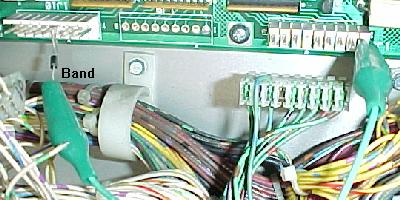
3m. When thing don't work: Infrared Optic Switches (Drop Target switches)
Williams also used optic light emitting diodes (LED's) for some switches,
even on the older System 11 games. Millionaire (1/87) appears to be the first
Williams game to use optics as switches. Mostly Williams used "U" shaped optics
for detecting the position of drop targets. The problem with this is
vibration. Often the optics will actually break off the circuit board because the drop
targets take so much abuse.
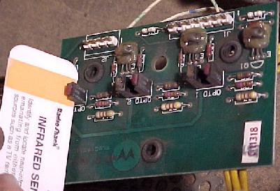
The optic board from a pre-system 11b drop target (note the lack of
any chips on this board). You can use Radio Shack's infrared detector
card to see if the opto transmitters are working. On these older optics,
the "red" side is the transmitter, and the "white" side is the receiver.
The transmitter is the side that 95% of the time dies. After all, it's
essentially a light bulb that can burn out.
|
|
If a drop target is not sensing when it is down, it's a good chance
you have an optic problem. The optic board is held to the drop target
with three "E" clips on rubber mounts. Remove the "E" clips and the board
will lift off the drop target assembly. Now inspect
the optics. If they are not broken, clean them with a Q-tip dipped
in Windex. It is amazing how often just cleaning optos in this manner
fixes them.
Optos have two sides to them: a transmitter, and a receiver. The transmitter
is the part that fails 95% of the time. Essentially the transmitter is a
light bulb, and all light bulbs burn out eventually. And the optics are
always "on", even when the game is in attract mode (another good reason
to turn your game off when not in use).
A nice tool to have in your tool box is a infrared detector
card. Available from Radio Shack or
MCM Electronics part# 72-6771 (800-543-4330 or www.mcmelectronics.com),
this $7 credit card sized card will show if the optic transmitter is
producing light. Without this card, you can not see this wave length of
light (well a digital camera can be used to see the optic light too).
So this handy little card is quite good to have. Remember you must
have the card positioned in front of the transmitter to see the light
on the orange colored band (having it in front of the receiver won't
show anything!). The "red" side of the "U" shaped opto is the
transmitter side of the optic.
System 11b and Later Optic boards.
With system 11b, the optic circuit was removed from the CPU
board. This meant that the optic board (for example on drop
targets) needed added circuitry to do the switch processing.
This was done by adding LM339 chips to the optic board.
If you are having problems with an optic board, and you know
the optics themselves are good, suspect the LM339 chips. These
are inexpensive chips; just replace them wholesale on the optic
board if in doubt.
New Style Optics on Optic boards with LM339 Chips.
The optics themselves were changed on the newer optic boards
with LM339 chips. The new optics used new style "U" shaped
optics (as used in the 1990 and later WPC games). Unfortunately
this new style of optics had a much bigger problem with
breaking leads, and falling off the optic board. Whenever
replacing these optics, put a dab of silicone underneath the optic
when mounting them to help prevent this problem.
Testing the LED Receiver (and Transmitter).
We talked about testing the transmitting part of the LED optic switch using
an infrared sensor card or digital camera. But what about the receiving side?
When the receiver is turned on by infrared light, there is about 1 to 1.5 volts DC
across the leads of the receiver. This means there is no switch closure.
When the light beam is blocked by something (a drop target or a pinball),
the LED receiver transistor turns off, and there is about 11 volts DC across the leads
of the LED receiver. Also there should always at least 1 to 3 volts across the
leads of the light transmitting LED. Infrared transmitters operate in the 1 to 3 volt
range, which comes from the 12 volt power supply, and is "dropped" down in voltage
by a resistor.
Another good way to test the LED receiver is using a plain flashlight. Put the
game into switch edge test, and shine a regular flashlight into the suspect LED
receiver. The switch should trigger in the switch test. This also tests the LED
transmitter - if the flashlight turns the receiver on and off yet the original
LED transmitter does not, there is no doubt a problem with the LED transmitter
(or the voltage going to it).
Replacing the Optics.
Be careful installing new optics. It DOES matter which way you install
them! If you install the new optic backwards, you will probably ruin it.
Remember on the old style optic boards, the red side of the optic
is the transmitter. On new style optics, the side of the optic
with the white "dot" or the "notch" is the receiver. The white dot
on these new style optics matches with a corresponding white dot
on the circuit board, to make installation easy.
Also use a dab of silicon under the optic when mounting them. This will give them
some shock resistance.
3n. When thing don't work: Score Display Problems
One of the most frequent system 11 problems relates to non-working or
weak score displays. Fortunately, often there is a very easy fix
for this problem.
The simplest thing to check when the score displays do not work
is the +100 and -100 volt DC power section of the power supply.
If either of these voltages are bad, your displays will not work.
And quite often, this power supply section does go bad.
Replace the 39k ohm Power Supply Resistors.
The major villain in the system 11 power supply are resistors R1 and R4. These
are both 39k ohm, 1 watt resistors. Very often either or both of these
resistors will go out of spec, or even completely open. This will
prevent the +100 and/or -100 volts from getting to the score displays.
These two resistors are mounted on the system 11 power supply board.
(on newer WPC games with alphanumeric displays, these are resistors R48 and R49 on
the alphanumeric display board). As a general rule, I always change these
resistors (trust me, they've had a tough life, and need to be replaced,
even if they test as "good").
If the high voltage fuses are not blown, and the score displays do not work,
first replace the 39k ohm resistors. These are
cheap and easy parts to replace (a lot cheaper and easier than replacing
score display glass!) Or at least check these with a DMM.
Replace these two resistors with "flame proof" 1 or 2 watt 39k ohm versions.
And make sure to mount the new resistors slightly off the circuit board,
so air can get under them for cooling.
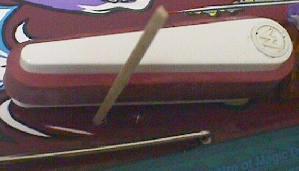
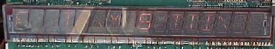
Note the score display is barely working. At first, you may think it's the
display glass itself. This is infact a common problem, where the displays
"outgas" and don't show as brightly, and eventually completely die. But
before you change the expensive score display glass, change the 39k ohm
resistors on the power supply with new 1 or 2 watt "flameproof" resistors.
|
|
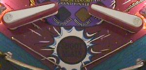
Here is the same score display after the 39k resistors were changed on the
power supply board. This cheap 50 cent fix shows that the score display
glasses themselves were good!
|

|
Replace the 100 volt Diodes with 91 volts Diodes.
Glass score displays are getting very expensive. To make matters worse,
there is now only one manufacturer of alpha numeric and numeric score displays.
Because of this, it is important to make the game's current glass score displays last as
long as possible. The best way to do this is to decrease the 100 volts
(which powers the displays) to 91 volts. This can be done by replacing
the zener diodes at ZR2 (Z2) and ZR4 (Z4) to a lower voltage diode.
The original diodes used at ZR2, ZR4 are 1N4764A. These are 100 volt,
1 watt zener diodes. Replace these with 1N4763A diodes, which
are 91 volt, 1 watt zener diodes. Now 91 volts (instead of 100 volts)
will power the displays. This will make your displays slightly less bright,
but it will also DRAMATICALLY increase their life span! Unless the current
score displays are really dim (and near death anyway), this is highly recommended.
This suggestion also applies to the later WPC games that use
alphanumeric displays. Change diodes D5 and D6 on the display board to
1N4763 diodes (some WPC games this is already done from the factory,
but the Funhouse schematics still show the 100 volt 1N4764 diodes).
As a rule, on every Williams System 11 pinball,
I always make the following changes to the power supply:
replace the two 39k ohm resistors R1, R4 with new flame-proof
versions. Often I will replace the two 1N4764A diodes ZR2/ZR4 with new 1N4763A diodes.
In a home environment it's not a huge deal to decrease the display voltage.
But if you are rebuilding the high voltage section of the board anyway,
it's a good idea to use the 1N4763 diodes instead. The only downside is if
the display glass is marginal (outgassing), lowering the 100/-100 voltage to 91/-91 may
make a marginal score glass not "glow".
So the downside to decreasing the display voltage from 100 to 91 volts
is if the score display glass is weak, and the displays
may not light up at the lower 91 volts. Just keep this in mind when lowering
the display voltage.
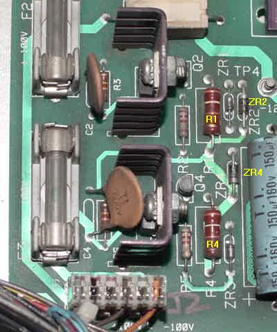
The high voltage section of a newer System 11 power supply
(Rollergames). R1, R4, ZR2 and ZR4 can seen here.
|
|
The high voltage section of an older Williams power supply.
|
|
Check the +100/-100 volts at the Power Supply board.
If either the -100 or +100 voltages are missing, none of the score
displays will work. These voltages should be from 90 to 105 volts, and
can be checked at power supply connector.
Power Supply D-8345-xxx (where xxx is the game number).
Used from High Speed to Swords of Fury. Remove power supply
connector 3J5 and check for these voltages with the power on,
directly on the 3J5 power supply header pins:
- 3J5 pin 1: ground
- 3J5 pin 3: -100 volts DC (or -90 volts if ZR2/ZR4 is a 1N4763)
- 3J5 pin 4: +100 volts DC (or +90 volts if ZR2/ZR4 is a 1N4763)
- 3J5 pin 6: +5 volts DC
Power Supply D-11883 and D-12246. Used from Taxi to Doctor Dude.
Remove power supply connector 3J2 and check for these voltages
with the power on, directly on the 3J2 power supply header pins:
- 3J2 pin 1 (orange): -100 volts DC (or -90 volts if ZR2/ZR4 is a 1N4763)
- 3J2 pin 3 (brown): +100 volts DC (or +90 volts if ZR2/ZR4 is a 1N4763)
- 3J2 pin 5 (black): ground
- 3J2 pin 6 (gray): +5 volts DC
WPC AlphaNumeric Display Board. Used on Funhouse, Harley Davidson, the Machine.
Check connector J306 and J307 for these voltages
with the power on, directly on the connector pins:
- J307 pin 1: input 85 to 90 volts AC (+/- 90 volts DC are created from this).
- J307 pin 4: input AC reference.
- J306 pin 1: +5 volts DC.
- J306 pin 3: ground.
After the voltages are tested with the above specified power supply
connector removed (if any voltages are missing first check the fuses),
now replace the connector (power off). Turn the power back on and
re-test the voltages. If the high voltage fuses blow immediately,
there is a short in a score display glass, or on the score display
controller board (usually a UDN6118 or UDN7180A chips - the UDN
chips can be tested for shorts, see below).
High Voltage Low - Check Power Supply Diodes ZR1/ZR3.
Like the two 39k ohm resistors, the two diodes at ZR1 and ZR3 (1N5990, 3.9 volts 1/2 watt)
on the power supply can start to
"leak" (on WPC alphanumeric games, diodes D1 and D2 on the alphanumeric display board).
When replacing these diodes, use a 1N4730A instead (3.9 volts 1 watt), as
this 1 watt version is more robust.
If the displays are weak and the 100 volt section is low (below 90 volts,
even with the score display glass power unplugged from the power supply),
try changing these two diodes (after changing the 39k ohm resistors first).
If the high voltage section is still low (below 90 volts), now its time to
rebuild the whole high voltage section (see below).
System9 versus System11 Score Display Data.
System9 uses 7-digit numeric displays only (no alpha-numerics).
Because there is less data traveling to the master display panel, and
there is no ribbon cable needed from the system9 CPU board to the display board.
System9 score display decoding is done using BCD (Binary Coded decimal) data,
and the master display board handles the BCD data decoding for the score displays.
With System11 the score displays are handled differently.
Instead of BCD data, the CPU board
controls the segments of the alphanumeric display directly. To
support this, Williams added a 26-pin connector for a ribbon cable to the
score display panel and some additional circuits on the system11 CPU board.
Blown high voltage score display Fuse(s) in the Backbox.
Every system 11 game at least one fuse to protect
the +100 and -100 voltages which power the score displays. Later games
have two fuses, one for +100 and one for -100 volts. These are located in fuse holders
in the backbox on the power supply board. If these fuse(s) are blown,
remove the high voltage power out connector from the power supply (as
discussed above in the voltage testing section), replace the fuses,
and power the game back on. If the fuse(s) blow again immediately,
the high voltage section of the power supply board will probably need to
be rebuilt. If the fuse(s) do not blow, there is a problem in the
score display glass or on the score display board.
A shorted score display glass or a blown UDN6118 or UDN7180 chip(s)
on the master display board can
cause the high voltage fuse(s) to blow on the power supply board.
These chips can short the +/- 100 volts directly ground,
and blow the fuse. To verify the UDN7180's are not the problem,
unplug all the connectors going to the master display board.
Now replace the power supply 100 volt fuse(s), and turn the
game on. If the fuse still blows, the high voltage section of
the power supply has failed. If the fuse does not blow, a UDN6118 or UDN7180
chip(s) on the master display board has failed, or a shorted score display tube is
the problem.
WARNING: if the high voltage section of the power supply has failed
and is rebuilt, it can be damaged *again* by a shorted display score glass
or a shorted UDN chip! The high voltage fuse(s) should protect against
this, but sometimes the fuse just don't blow fast enough to save
the power supply's high voltage components.
WARNING: Schematic Mis-Prints 4049 vs 4050.
On some system11 schematics (such as Earthshaker)
chip U8, U9, and U10 the schematics says these are 4050 chips on the display controller board.
But this is *wrong*! They are actually 4049 chips (hex inverter buffer). If 4050
(non-inverting hex buffer) chips are put in by mistake it can cause damage
and the displays will not work!
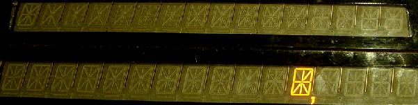
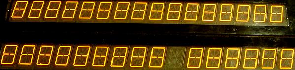
A closeup of a missing segment caused by a bad
UDN7180 chip on the display controller board.
|
|
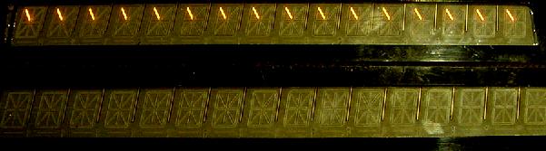
Bad UDN7180 chip on a 16 digit alpha-numeric from Earth shaker, in display test.
Both the top and bottom display should show the same segment. But the bottom
display is missing this segment because of one bad UDN7180 chip on the display
controller board. A single leg on the one bad UND7180 chip is causing this problem
for the entire lower 16 character display (or for both lower displays if this game
was pre-Taxi).
|
|
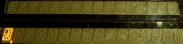
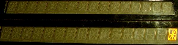
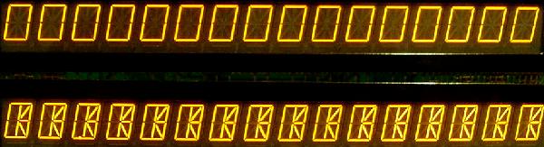
Bad UDN6118 chip on a 16 digit alpha-numeric from Earth shaker, in display test.
The 6118 chip controls characters. The top most picture shows a single UDN6118 chip
completely removed (if this was a pre-Taxi game, that would be all characters missing
for an entire display). The next shows several bad legs on the 6118. And the last
picture shows one bad leg on the UDN6118.
|
|
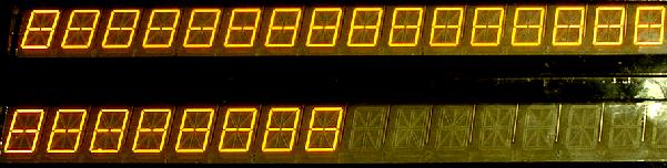
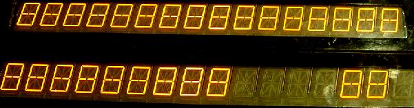
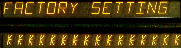
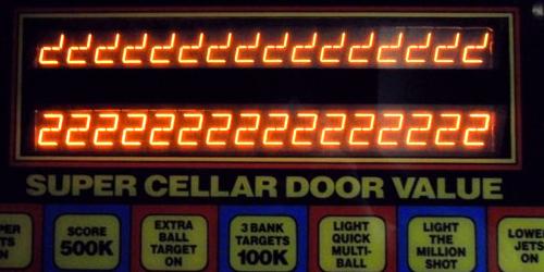
Bad 4049 CMOS chip at U7 on a 16 digit alpha-numeric from Earth shaker.
The top most picture shows a single 4049 chip with the game just booted (batteries
missing, hence the "Factory Settings" error message). The last picture shows the
game in display test - just zeros should be shown on both upper and lower displays.
|
|
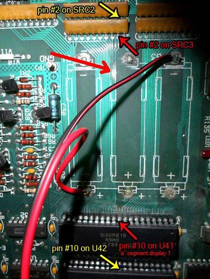
Battery Corrosion and Missing Display Segments.
Be aware that the traces going to PIA U41 go right under the
battery holder on the CPU board. Remember PIA U41 is responsible for
the display segments, and a corroded or broken trace here can
prevent a display segment from lighting. The original battery holder
will have to be removed to check these traces for corrosion.
Remember any battery corrosion is a bad thing, and it will come
back to haunt you if the problem is not addressed. On the pictures
below the "A" segment signal going to the master display board was
tested with a logic probe and found to be missing on the CPU board (thus eliminating
the master display board.) Following the signal back past the SRC3
and to the PIA at U41 it was found the trace under the battery holder was broken due to corrosion.
Battery corrosion on this system11c CPU board has caused a
display segment (and a flash lamp) to not work. The corrosion
effected several areas, shown with the arrows.
Pictures by AceBH.
|
|
Testing the UDN7180/UDN6118 Chips and Score Glass for Shorts.
Both UDN chips are 18 pin chips. The four corner pins
of the chips do *not* need to be tested (pins 1,9,10,18).
But all the other pins can be tested. Repeat this test for
each of the UDN6118 and UDN7180 chips:
- Turn the game off.
- Remove the high voltage power supply power connector (3J5 or 3J2, depending
on which power supply the game has).
- Put the DMM on the *diode* setting.
- Connect the red DMM lead to ground.
- Put the black DMM lead on each UDN pin 2 to pin 8.
- A reading of .5 to .7 should be seen.
- Put the black DMM lead on each UDN pin 11 to 17.
- a NULL (no) reading should be seen!
Note if the display glass itself is shorted (it does happen!),
it MAY show up when testing the UDN pins 11 to 17.
So how do we isolate the problem to the UDN chip or the
display glass? First test the UDN chip. If any of the pins
(but mainly pins 11 to 17)
fail the test, desolder the suspect UDN chip from the
master display board WITHOUT DAMAGING IT (these chips are
expensive, and if it's good it would be nice to save the chip from
desoldering damage). Install an 18 pin socket for the chip, and buzz out the
socket making sure there are no shorts, and all traces connect
to the socket.
Now again use the DMM and repeat the
above UDN test procedure ON THE SOCKET (no chip installed). That is,
with the DMM on diode function and the red DMM lead
connected to ground, test pins 11 to 17 of the SOCKET
with the black DMM lead. Again, a null reading should
be seen. If a null reading is seen, the UDN chip has failed
and needs to be replaced. If a null reading is *not* seen, chances are
really good that the score display glass itself is shorted.
If the score display glass fails the test, it will need to be
replaced (there is no way to fix it). After the score display
glass is removed (and before the new glass is installed),
put the UDN chip in the newly installed socket
and retest the chip as described above.
A Summary of the UDN Chips.
- UDN7180A : There are at least four of these on the master display
board. These control the SEGMENTS.
Note the "A" designation on the 7180,
signifies a plasitc case (instead of ceramic).
- UDN6118A-1 : There are at least four of these on the master
display board. These control the DIGITS.
Older Williams games specify a UDN6184A, which is an older version of
the UDN6118A-1 (it's Ok to replace a 6184 with a 6118).
Note the "A-1" designation on the UDN6118A-1. This
signifies a higher voltage rating (100 volts) than a UDN6118A (90 volts).
These seem to be less critical than the 7180 in regards to voltage,
but it's still best to get the 6118A-1 version if possible.
The UDN6118 is a fairly inexpensive (up to $5 each), and is starting to
get expensive as they are no longer made by any chip manufacturer.
The UDN7180 is a worse.
These are a hard to find chip, and usually sells for $5 to
$25 each! So be careful when working with a 7180 chip.
Extra Unused UDN7180 on some Games with D-10877 display panels.
On some system11 games like Pinbot that use the D-10877 two alpha-numeric and two numeric
display board, there is an installed UDN7180 chip at U12 that is not used
by the game. If one of the other UND7180 chips fails, the U12 chip
can be removed and transplanted to the needed position on the master
display driver board. Then the U12 position can be left empty. This
doesn't work on all games, but it does work on Pinbot.
14049 Partial Segment Failures on Score Displays.
Sometimes only parts of a display aren't displaying or are locked-on, and only
on certain numbers. For example, the top part of a "0" or "7"
are not displaying or are always locked-on. It can even be so strange so that the missing
segment will work on some numbers or letter, but not on others.
This can be caused by one of the hex input buffer 14049 or 4049 chips at U10, U11, U15-U18
or U7-U9,U10-U11 on 16 character display boards.
Note on the schematics sometimes these are mis-labeled as 4050 chips!
But these 4049 chips are CMOS and very static sensitive. You can check these with your
DMM set to diode test:
- Red DMM lead to 4049 chip ground pin 8.
- Use black DMM lead and probe pins 2-7, 9-12, 14-15 of each 4049 chip.
- A reading of .6 to .7 should be seen.
Any reading below this indicates a problem with the chip.
|
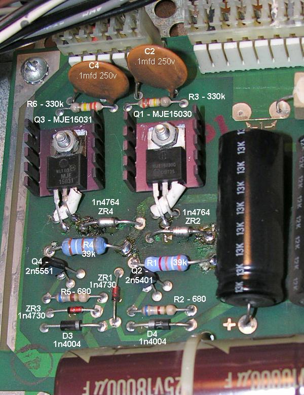
System11 Power Supply schematic using MJE15030/31 transistors. |
|
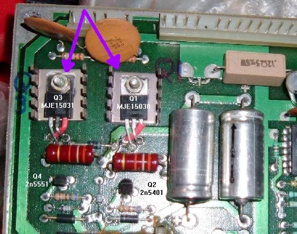
The high voltage section of a sys11 Williams F-14 Tomcat power supply.
Note the replacement of the SDS201/SDS202 transistors with crossed leg
MJE15030 and MJE15031 transistors.
|
|
The high voltage section of a sys9 Williams Sorcerer power supply.
Note the replacement of the SDS201/SDS202 transistors with crossed leg
MJE15030 and MJE15031 transistors.
Picture by Steve K.
|
|
Rebuilding the 100 volt Power Supply Section.
If any of the high voltage fuses are blowing and it's not
caused by a UDN chip or bad score glass,
the 100 volt power supply section probably needs to be rebuilt.
The following parts will need to be replaced on the power
supply board. If you buy a HV rebuild kit (offered by several companies), be sure
to install all the parts included in the kit. Here's a general
list of what should be replaced and what is included in most rebuild kits:
Positive 100 volt section System 11 parts to replace:
- Q1 = MJE15030 transistor. System11B and later should originally use a
MJE15030 (where sys11 and sys11A use the SDS201).
On older sys11/sys11a games that originally use a SDS201
(no longer available) a MJE15030 can be substituted,
but the leads must be "twisted" (so the emitter, base and collector match
the circuit board, see picture below).
Also a MJE340 (NPN 300 volt transistor) or
a 2N3440 with a "star" heat sink can be used.
- Q2 = 2N5401 (PNP 160 volt or higher transistor) or MPSD52 or NTE288.
- ZR1 (Z1) = 1N4730A (3.9 volt 1 watt) diode. In a pinch, use a 1N5990 (3.9 volt 1/2 watt).
- ZR2 (Z2) = 1N4763A (91 volt, 1 watt) diode. This replaces the original
1N4764A (100 volt, 1 watt) diode, to increase score display life.
- D3 = 1N4004 diode.
- R1 = 39k ohm, 1 or 2 watt flame proof resistor.
- R2 = 680 ohm, 1/2 watt resistor.
- R3 = 330k ohm, 1/2 watt resistor.
- C2 = 0.1 mfd 250 volt metal polyester capacitor.
Negative 100 volt section System 11 parts to replace:
- Q3 = MJE15031 transistor. System11B and later should originally use a
MJE15031 (where sys11 and sys11A use the SDS202).
On older sys11/sys11a games that originally use a SDS202
(no longer available) a MJE15031 can be substituted,
but the leads must be "twisted" (so the emitter, base and collector match
the circuit board, see picture below).
You can also use a MJE350 (PNP 300 volt transistor) or
a 2N5416 with a "star" heat sink.
- Q4 = 2N5551 (NPN 160 volt or higher transistor) or MPSD02 or NTE287.
- ZR3 (Z3) = 1N4730A (3.9 volt 1 watt) diode. In a pinch, use a 1N5990 (3.9 volt 1/2 watt).
- ZR4 (Z4) = 1N4763A (91 volt, 1 watt) diode. This replaces the original
1N4764A (100 volt, 1 watt) diode, to increase score display life.
- D4 = 1N4004 diode.
- R4 = 39k ohm, 1 or 2 watt flame proof resistor.
- R5 = 680 ohm, 1/2 watt resistor.
- R6 = 330k ohm, 1/2 watt resistor.
- C4 = 0.1 mfd 250 volt metal polyester capacitor.
When installing the new parts, cut the old parts out first.
Then use a solder sucker and clean out the circuit board holes.
Make sure you install new resistors slightly off the board,
to allow for air circulation. Solder all parts on both sides of
the board if possible. If using a HV rebuild kit, install all the parts.
If you're buying the parts individually yourself, it is best to replace
everything listed above all at the same time (though I have been known to
skip the resistors/caps if they test "good" with my DMM, but that's probably
not a good idea).
WARNING: if the high voltage section of the power supply has failed
and is rebuilt, it can be damaged *again* by a shorted display score glass
or a shorted UDN chip! The high voltage fuse(s) should protect against
this, but sometimes the fuse just don't blow fast enough to save
the power supply's high voltage components.
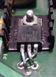
A replacement MJE15031 in an older system 11
power supply. The leads on the MJE15030 and
MJE15031 must be "twisted" to replace the
older SDS201 and SDS202 transistors. This should
ONLY be done on power supplies that originally
used the older SDS201 and SDS202 transistors.
It's a good idea to use heat shrink tubing on the
crossed leg to prevent a short.
|
|
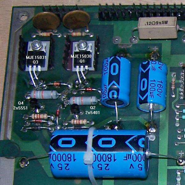
Twisted leads on the MJE transistors used on a F14 Tomcat sys11a power supply.
These MJE transistors replace the original SDS transistors at Q3 and Q1.
|
|
IMPORTANT NOTE: On older System 11 power supplies, Q1 and Q3 used
the discontinued SDS201 and SDS202. These can be replaced with
MJE15030 and MJE15031 respectively, BUT the legs must be "crossed"
as shown in the picture above!!
When installing the newly fixed board, measure the output
voltages BEFORE you plug in the high voltage connector (3J5) going to the
score displays! Output voltage should be between 90 and 105
volts.
Resistor & Capacitor Networks Causing Missing or Locked-On Score Segments.
On the CPU board at SRC1-SRC9 there are resistor &
capacitor networks.
These are similar to the resistor networks
used in the switch matrix, and described
above. But there are also capacitors inside the network, in addition
to the resistors. The resistors are pull up resistors, and if one doesn't
work (battery corrosion), a missing display segment is the result.
On a Williams CPU board,
these have eight resistors (1k or 4.7k ohms) and eight capacitors (470 pfd),
in a ten pin SIP package. Pin one of the network is tied to +5 volts and
connected to the eight resistors. Pin ten of the network is tied to ground
and connected to the eight capacitors.
These are a real bear to find, but they are made by
BI Technologies, their part series CR10-S with 4.7k ohm
resistor and 470 pfd capacitor. Unfortunately I can't find anyone
that has these in stock without ordering 5000 of them!
Vishay also has some for sale (their TRC schematic 09 series at
www.vishay.com/doc?68007),
but again we can't buy them in small quantities.
These SRC resistor/capacitor networks can be substituted with a
10 pin bussed SR (resistor only) network though. To install just cut
pin 10 of the SR network, so it's not connected. This will work just
fine, and is really the only choice we have.
Here's a run down of what these SRC networks are used for:
- SRC6 (1k/470 pfd) = switch matrix columns.
- SRC2,SRC4,SRC5 (4.7k/470 pfd)= score display data.
- SRC7,SRC8 (4.7k/470 pfd)= score display digit strobes.
- SRC9 (4.7k/470 pfd) = score display BCD.
- SRC1,SRC3 (4.7k/470 pfd)= "widget I/O" (the sound board).
On score displays, for example, if segments h,j,k,m,n,p,r are missing, this could
be caused by a failed SRC5 on the MPU board. Since SRC1-SRC5 is right above
the battery holder, often these fail due to battery corrosion.
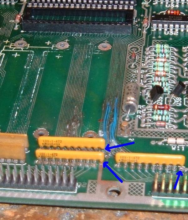
The SRC resistor/capacitor networks SRC1-SRC3 replaced with SR variants
for the score displays on a High Speed. Note pin 10 is cut and not connected.
This fixed the missing segments on this game.
|
|
Note that these SRC networks can not be tested "in circuit".
That is, they have to be removed from the board to get a good
test. Usually the resistance part of the SRC shows less than
the value stated for the SRC (.6 to 2.2k ohms, versus 4.7k ohms).
In order to test them they need to be removed from the circuit board.
In the case of SRC6 (switch matrix columns) on earlier system11 CPU boards,
if the original SRC resistor/capacitor network can not be found,
it can be replaced with a straight resistor network (with no capacitor).
This also works with the SRC1-SCR5 and SRC7-SRC9.
If this is done, a "1k x 9R" bussed resistor network can be used
(or heck even a "4.7k x 9R" bussed resistor network). But it
must be installed correctly! This bussed resistor network will have
nine pins (not ten), with one "common" pin. The common pin one
of the resistor network must go the board's pin 1 (+5 volts).
The remaining open pin on the board (ground) is not used.
This works because Williams installed some optional capacitors at
C49-C56 (.01uF). If replacing SRC6 with a straight resistor network,
caps C49-C56 should be installed. In most cases these are installed
from the factory, but it's best to double check. The caps in the SRC
networks are really redundant, that's why straight resistor networks
work in their place.
The SRC resistor/capacitor schematic from Vishay.
|
|
As far as SRC1-SRC5 and SRC7-SRC9 go, if the original style SRC networks
can not be found, you can also make your own (though straight
10 pin bussed resistor networks work, with pin 10 cut - this is far easier than
making your network.) But if you like the punishment, the idea is that pins 2-9 of the circuit
board will have its own pull-up resistor to +5 volts, and it's own
capacitor to ground. Buy eight 4.7k ohm
1/4 watt resistors and eight 470 pfd capacitors.
Put one lead of each resistor in the "middle" circuit board holes
pins 2-9. Then tie all the loose ends of the resistors together,
and attach them to +5 volts (pin 1). Now put one lead of each capacitor
in the "middle" circuit board holes pins 2-9. Then tie all those loose
ends of the capacitors together, and attach them to ground (pin 10).
These SRC packages can also be made using the UNI-SIP devices at
www.capitaladvanced.com/uni-sip.htm.
Score Display Ribbon Cable Problems.
System 11 and WPC alphanumeric games have a fairly small problem that can appear to
be a major one. If you have had the CPU board out of your game,
and now your score displays don't work, check the ribbon
cables connecting to the CPU board. It is very easy to install
the cables offset by 1 pin to the left or right. In most cases
this will not damage the electronics. And always make sure the
red strip on the edge of the cable lines up with pin number one
on the CPU board connector.
Slow Display Strobing Problems.
Sometimes the score displays can have a slow reveal and wipe
pattern that leaves only three or four digits on at a time.
This can show as three or four digits in the player one and three displays,
then the credit display, and finally the player two and four displays.
Then the next three or four digits display the same way across all the score
displays. You never see the entire display lit. The game will
do this in game or game over mode, just repeating the pattern. The
score displays do however keep score accurately. Also this problem
can sometimes be seen in a single score display.
This is usually caused by weak high voltage going to the score displays.
Instead of plus or negative 100 vdc, the voltage can be as low as 50 volts.
This low voltage can be caused by resistors R1 and/or R4 (39k ohms) on the power
supply board, or a bad high voltage capacitor C1/C3 (100 mfd 250 volt),
or C2/C4 (0.1 mfd 250 volt metal polyester cap) on the power supply board.
Alpha-Numeric and Numeric segment letter designations.
|
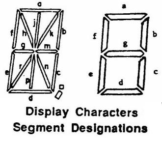
|
More Display and Segment Problems: the UDN7180/UDN6118 chips.
If you are having display problems (and you have fixed the power supply
board), the next course of action is to check the UDN6118 and UDN7180 chips
on the Master display board. The UDN6118's control the strobe pulses,
and the UDN7180 control each segment in the display.
There are as many as four UDN7180 chips and four UDN6118 chips on the master display board.
If one UDN7180 fails, this will affect one or two score displays (one display on the
newer system 11 games with two 16 digit displays, or two score displays
an older System 11 games with five displays). If a UDN6118 fails, usually half
of the display won't work! But if either a UDN7180 or UDN6118 fails, at
least some of the display should work. If a display doesn't work at all
(no segments are displaying), and the +100/-100 volts are present, chances are
really good the display glass itself is bad. In fact, bad display glass is
quite common (especially if the high voltage was not reduced from 100 volts
to 91 volts, as described above).
The UDN6118 and UDN7180 both have the same pinout: pins 1 to 8 are the input
side of the chips, and pins 11 to 18 are the output side (but pins 1 and 18
are often not used on the UDN7180). Pin 9 is ground,
and pin 10 is high voltage (-100 volts). Check the schematics
to see exactly which chip controls which display when diagnosing these.
Both the UDN chips are easy to test though: both have
an input and output side. If the input side is pulsing
(a logic probe can be used on the input side ONLY, logic
probes test low voltage), that usually means everything
up to the 7180 chip is good, and a good signal is getting
to the chip.
Next check the output side of the 7180 (note this can NOT be tested
with a logic probe, as it is 100 volts!) Use an oscilloscope for
this testing, set to a 100 volt range. The 7180 outputs should be pulsing too.
(If in doubt, us an oscilloscope on both the inputs and outputs.)
To perform these these tests,
put the game in it's diagnostic display test. Then single stepped
to the next digit test (all zeros, 1's, 2's, etc) and check the input and output
pins at each step. If the input side is pulsing, and the output side is not,
then the chip is probably at fault.
Here's an example:
Problem: segment 'b' (top right) always on for players 1 and 2, and ball-in-play
score display (but not credit display!).
Answer: looking at the display board schematic found that U13, U14 (UDN7180)
are common components to these displays. Chip U13 drives segments
"h,j,k,m,n,p,r" and the period, while U14 drives "a" to "g" and the comma. Since
UDN7180's are becoming rare and are expensive, the input and output signals were double
checked by comparing them with a logic probe (or an oscilloscope).
Putting the game in display test so it could be single stepped to the next digit
test (all zeros, 1's, 2's, etc). On chip U14, the input pins 1-8 showed activity and
changed when I advanced to the next digit test. Next tested the U14 output pins 11-18.
The output pin 18 (for the "b" segment) was constant and did not change when the test
was advanced. The conclusion was to removed and replace the UDN7180 at U14 (after
installing a socket), which fixed the problem.
Segment Still doesn't work: Check the Resistors before replacing a UDN7180.
Since UDN7180 chips are expensive and hard to find, you want
to make sure it really is the problem before you replace any. If you have
checked/replaced the 4050 chip(s) and probed the UDN7180 and UDN6118 chips,
there is one more thing you should check. That would be the resistors
coming off the UDN7180 chips. Though it doesn't happen a lot,
a bad resistor solder joint or bad resistor itself could be your problem.
Check these resistors with your multi-meter
to make sure they are at the correct value. Using the schematics, find
the segment letter identifier you are missing. Then follow that segment
through the UDN7180 and its corresponding resistor. Make sure that resistor
is within 10% of the schematics specified value. Or if you don't have
a schematic, just check ALL the resistors on the Master display board with
your multi-meter. The slightly larger 1/2 watt resistors tend to be
the more troublesome resistors.
Here's the credit display on a F-14. Note the left most
character is scrambled. This was not a master display board
problem, but was rather a CPU board PIA and a 74154 chip
problem (they were shorted internally).
|
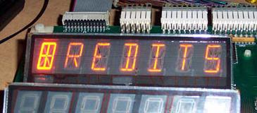
|
"Outgassed" Score Displays.
Score display glass has a limited life; it does not last forever.
Time will eventually kill these, and the display will "outgas"
and fail. This is why it is suggested to reduce the high voltage from
100 volts to 91 volts (see above).
Because of the high voltage involved with score displays,
the anode and/or cathode inside the diplay glass breaks down.
This results in the "outgassing"
of impurities that eventually change the internal gas properties, so the display
can't glow (the gas must be very pure for the display to work).
There is no fix for this short of replacing the display glass (which
have become fairly expensive now). Sometimes score glasses short
too (this will blow the -100/+100 power supply fuse). But really it
is quite common for the score display(s) to outgas and die, showing no sign
of life. If +100/-100 volts is present, and a display glass is totally
dead (no segments lits), chances are really good that the score display
glass itself has outgassed, and needs to be replaced.
Frank adds that often the score display glasses are
just dead. Many system11 games will have two or even three or all four displays
dead. Check the displays and if there are little bright speckles like tiny
diamonds when the game is on, this usually means the display is outgassed.
Also there is a little are below
the visible section on the display with two tiny wires. If some white dust is seen,
that's also a good indicator of an outgassed display.
Versions of the Alpha-Numeric Display Boards (Banzai/Taxi/Police Force).
Taxi and Police Force use a slightly different style of
display board. Both these games use the two 16 digit alphanumeric score
display, but also have an extra third 7-digit numeric score display.
In order to accomodate this, the standard system11 alpha-numeric
display board was modified slightly and a second ribbon cable connector
was added to the board.
Taxi and Police Force have an alpha-numeric display at the top in the backbox,
and an alpha-numeric display below it in the backbox which is only used for numerics.
Diabled on the bottom 16-digit has the following disabled: right side hash mark,
some commas and periods. These item are removed from the bottom 16-digit display
so the circuitry could be used to drive the additional 7-digit numeric display.
The bottom 16 digit display on these
games only uses 8 segments (the middle segment of the display is
used to make the number zero into an eight, which is two segments). This leaves six
segments and the "comma" left unused. The unused segments are then used
to drive the extra display. This is the reason there's a second place to hook up
a ribbon cable on the Taxi/Police Force display boards.
The Taxi/Police Force style display board can be converted to work in the
other 16 digit alpha-numeric system 11 games, with a small modification.
Simply install the missing seven resistors into locations R62 to R68 on
the Taxi/Police Force display board.
Likewise if a display from a BK2000 was used in a Taxi, a few things have to be added:
U3 (UDN6118) and resistors R9-R13 and R15-R18
(all 10K resistors) Also remove R67, R65, R64, R62, R60, R57, R56, and R54.
Banzai run also uses a unique display board. The Master display board is
the same as pre-Taxi games, but the display board itself is unique. It is
a single sided board and often has delaminated board traces. Remember
Banzai uses two 7 digit alpha-numeric displays and two 7 digit numeric
displays.
16 Character Alpha Numeric Display Boards.
System11 games Taxi and later can have two different styles of 16 character
alpha-numeric display boards. There is one style where the displays are
stacked vertically. This is a single board with both displays. Other
games (like Bugs Bunny) have two display boards mounted horizontally
each with one 16 character display. Note these games use a "R" (right)
and a "L" (left) display board, and are NOT interchangable. The connectors
are the same for each board, but if the "L" board is used in right
side, it will display scrambled text. Note the "R" board has one additional
.156" Molex connector compared to the "L" board.
System 11 power supply schematic from Big Guns (games with Auxiliary power
supply boards) to Cyclone. The only difference in power supplies after Cyclone
is the lack of GI connectors on the power supply board (these were moved to
the Interconnect board). Note diodes Z2, Z4 (1N4764) which should be changed
to 1N4763 diodes, and resistors R1,R4 which should be replaced with new
flame-proof 39k ohm 1 or 2 watt resistors.
| |
|
3o. When thing don't work: "Factory Setting" or "Adjustment Error"
(Battery Problems)
Often when you buy a used system 11 game, upon power up, you'll get an error message
stating, "Adjustment Error" (if the coin door is closed) or
"Factory Setting" (if the coin door is open). This message indicates that the CPU RAM chip
at location U25 on the CPU board has forgotten the game's bookkeeping and options settings.
If the coin door is closed, and the batteries are dead, you'll get an
"adjustment error" message.
|
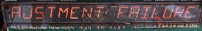
|
If the coin is open, and the batteries are dead, you'll get a
"factory setting" message. You can also get either above message
if the battery holder is bad, or the RAM chip at U25 has failed.
| |
|
The difference between these two messages is simple; when the coin
door is closed (and the memory protect switch which is connected to
the coin door is pressed in), the CPU is electrically blocked from accessing
the RAM at U25. Therefore the game can only reset the factory settings if
the coin door is open. If the game ever comes up with the "Adjustment
Failure" message, the coin door must be opened to get past this message.
Why Do I Get These Error Messages?
Most often, these errors occurs because the three "AA" batteries on the CPU board have
died. These batteries should be replaced every year with good quality alkaline batteries
(batteries are cheap, battery damage is expensive).
The three batteries must keep at least +4 volts of power to the U25
RAM chip for it to remember. When power goes below +4 volts, memory reset can occur
(and you get the "Factory Setting" error message).
A bad battery holder. At first glace, this holder looks fine. But
the two battery contact points on the left have corroded and fallen
off. The contact on the right is the only one intact. These contact
points are actually rivets, but corrosion will cause the face of the
rivet to break as it goes through the fiber insulator, and the face
of the rivet that contacts the battery falls off.
|
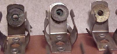
|
Battery Corrosion.
If the three AA batteries have leaked, this is a major problem as
the corrosive fluids in the battery can eat the copper traces right
off the CPU board. See this section
for help with that. And as always, better to be safe than sorry -
remote mount the three AA batteries off the CPU board. This way if the
batteries do leak, at most a $5 battery holder is ruined.
The Battery Holder: a Weak Link.
If after replacing the batteries, you still get a "Factory Setting" error,
suspect the battery holder. Use your DMM and check the battery voltage
at the CPU board. With the game off, put your DMM on DC volts and
put the black lead on ground (the grounding strap or on one of the screws
holding the CPU board in place). Put the red lead on each of the CPU board's POSITIVE
battery terminal SOLDER POINTS. Test each of the three batteries' positive leads
individually. You should get about 1.5, 3.0, or 4.5 volts at each battery
(note the batteries are additive and the first battery in the chain will
give you 1.5 volts, and the last battery will give you 4.5 volts).
If you don't these positive voltages, suspect damaged battery holder terminals.
These corrode quite often if new batteries aren't installed religiously.
Replace the battery holder and re-test to ensure proper repair.
A battery gone bad. Note the white "fur" on the bottom of
the battery, and how it has corroded the chip and socket
below it. The battery holder, chip and socket must all be
replaced. Also the board must be washed with a mixture of
50/50 water and white vinegar (a mild acid) to neutralize
the alkaline battery gunk, and then rised with water. After
drying, the corroded areas can be sanded clean to the bare
copper traces, and the components replaced. If the board
isn't washed with this vinegar solution, the corrosion will
return.
|
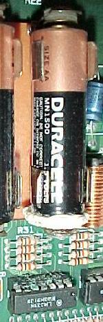
|
A Better Replacement Battery Holder.
The best battery holder to buy is the new black plastic battery
holder used in WPC-S and later games. This is Williams part# A-15814. This design
of battery holder is much better than the original system 11 design, and
will fit perfectly on a system 11 CPU board.
A EVEN Better Replacement Battery Holder.
The best approach to battery holder replacement is to
install a remote battery holder. This way if the batteries
do leak, you wreck a $5 battery holder instead of ruining
a $300 CPU board.
Personally I purchase battery holders that hold four AA
batteries. In the first battery bank, I install a 1N4004
diode (band direction is important, see picture below,
but the band connects to the red wire side of the battery holder).
Though the diode is not needed, I highly recommend using
the diode. It's secondary protection to the batteries, and
it lowers the battery voltage just a bit. This is a good thing,
as you will get the "Adjust Failure" message sooner, reminding
you to replace those batteries BEFORE they leak!
Using a remote battery holder in an Earthshaker (with an original sys11 cpu
board). Note how a 1N4004 blocking diode is used in this setup, which lowers the
battery voltage slightly. This is a good thing, as the game will give a "Adjustment
Failure" reminder sooner, hopefully encouraging battery changes sooner and preventing
the batteries from leaking. Remotely mounted batteries are a good idea to save CPU
board corrosion repairs.
|
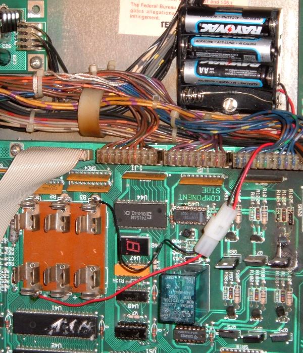
|
Using a Coin Style CR2032 Battery.
Lately I have really been moving to using these coin style
CR 2032 batteries on system11 CPU boards. They last a really
long time (up to 10 years) and don't leak. The cost is competitive
to using a remote AA battery pack too (about $1 for the battery
and $1 for the holder from places like BG Micro.)
The installation is very clean and simple, and if the CPU board is removed from
the game there isn't a cable or battery holder hanging off the board.
A cr2032 coin battery and socket installed on a system11b CPU board.
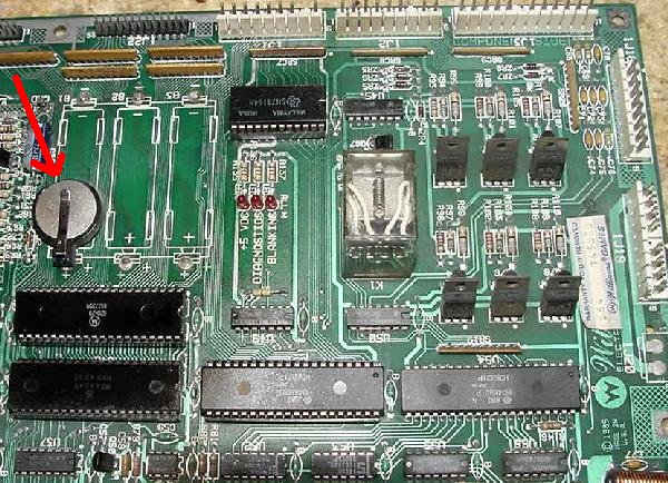
|
Testing for Battery Voltage at the Blocking Diode.
After testing the batteries at the battery holder, test for voltage at the
blocking diode D2 (1N4148 or 1N914), which is next to the left bottom side of the
battery hold on the CPU board. With the game off, put the black lead on the backbox
ground strap, and put the red lead on either side of the diode. You should
get around 4.2 to 4.8 volts. The banded diode of the diode connects to
the U25 RAM chip pin 24, and should be about .3 volts less than
the non-banded (bottom) side of the diode. If you only get voltage on only one
side of the diode (the top side or non-banded side,
which connects directly to the battery),
the diode is bad and needs to be replaced. If the voltage is the same on
both sides of the diode, again this diode is bad (shorted) and must be replaced.
Next check for voltage at the U25 RAM chip. With the game off,
you should get about 4.3 volts DC at pin 24 of
chip U25 (ground is pin 20 by the way). If you don't, the battery
voltage is not getting to the U25 RAM chip. This will cause
the game will boot up with the "Factory Setting" or "Adjustment error". Note
pin 24 of the 24 pin RAM chip is in the same position as pin 1 of
the chip, but on the opposite row of pins. Pin 1 is designated with an
impressed "dot" right on the top of the chip. This chip is a 2k by 8 CMOS static
24 pin RAM chip. The part number will be 2016 or 6116-L or NTE2128.
Early system 11 games specify this chip as a 5177, but this chip
can be replaced with a 6116 instead.
You can still have problems even if you installed new batteries and all the
voltages check out. If your game is still giving "Factory Setting" or "Adjustment error",
you may have a bad CPU U25 RAM chip. But make
sure you double check that battery holder. Even minor corrosion can cause
this problem. The voltages may all check out, but the corrosion may be enough
to limit CURRENT, and cause this problem.
More "Blocking" Diode D2 Problems.
The three AA batteries are connected to the U25 RAM chip via a "blocking"
diode. This 1N4148 switching diode at D2 is connected in series between
the battery and the U25 RAM chip. It's job is to prevent +5 volts
from going back to the batteries (it only allows power from the batteries,
not to them). Sometimes this diode shorts out or
goes open. If this diode shorts, the CPU board will try and charge the
three AA batteries! This will cause the batteries to leak, and could
damage your CPU board. If the diode goes open, the batteries will never
power the U25 RAM chip, and the game will boot up with the "Factory
Setting" or "Adjustment error". Check this diode with the game off and your DMM set to the
"diode" setting. You should get between .4 and .6 volts in one direction,
and a null reading in the other direction. You can also test the diode
(with the game off) by setting your DMM to DC volts. Put the black lead on ground, and
you should get 4.2 to 4.8 volts on either side of diode D2 (the banded side
will be about .5 volts higher). If you
only get voltage on one side, the diode is open and needs to be replaced.
Changing Batteries.
If your game is working, and it's time to replace the batteries, follow
this procedure. But the way, you should change the batteries in your
game every year, or every two years at most (to prevent any battery
leakage problems):
- Remove the backglass and gain access to the CPU board.
- Turn the game ON.
- Note the orientation of the installed batteries (All positive terminals up or
to the right?).
- Remove the old batteries and discard.
- Check the battery holder's terminals for any corrosion. Clean with 220 grit
sandpaper if any corrosion. If damaged, turn game off and replace battery
holder.
- Using a Sharpie pen, write today's date on the new batteries.
- Install the new batteries.
- Turn the game off.
If you install new batteries with the game turned on, the machine will not
forget the old option settings or bookkeeping totals.
Clearing a "Factory Setting" or "Adjustment Error" Message.
To clear these messages, you first need to fix the problem (replace the
batteries and/or battery holder, replace the U25 RAM, etc.). After this
is done, turn the game on. Then press the center red coin door button
into the down position. Now press the black button closest to the coin
door. If you have an "adjustment error", the game will beep and flash
the "factory setting" message.
Once you have the "factory setting" message, press the black button
closest to the coin door twice. Then move the center red
button to the up position. Then press the black button closest to the
coin door again (twice if you had an "adjustment error" message).
The game should now go into attract mode.
New CPU Batteries Die very Quickly.
Just to the side of the battery holder on the CPU board, there are two "blocking"
diodes, D1 and D2. These form a diode bridge, blocking the battery
voltage from the power supply, and vice-versa.
Where these two diodes meet, power goes to the U25 RAM. This way when
the game is on, power for the U25 RAM is drawn from the power supply. But when the
game is off, power for the U25 RAM is drawn from the batteries.
If either diode D1 or D2 is bad, it can let the batteries attempt
to power all the +5 volts logic for the whole CPU board when the game
is powered off. Or it can let the +5 volts from the power supply
attempt to charge the batteries when the game is powered on. In either
case, this will cause the batteries to die quickly.
If you have batteries that are dying very quickly, replace both
diodes D1 (1N5817) and D2 (1N4148) on the CPU board.
3p. Sound.
System 9 Sound Problems.
System9 and System11/11A have a similar set up
for sound. That is, the CPU board contains a couple
sound section, and addition sound (or speech) is provided
by an auxilary board.
On sys9, the main game sounds are handled by the CPU board's
sound section. This has a separate 6808 processor and a 6821 PIA
along with a sound amplifier section. The speech is handled by
a separate speech board, much like the speech board used in
System7 (but with larger ROM space). The CPU and Speech boards are connected together
via a large ribbon cable (unlike System11 which uses a much smaller
ribbon cable).
If the sound and/or speech does not work on a system9 game,
it's best to figure out if the problem lies on the CPU board
or the separate speech board. To do this, remove the ribbon cable
from the CPU board. Now examine the ribbon cable connector on
the CPU board (it is vertically mounted on the lower right edge
of the CPU board). There are two vertical rows of pins on this
male ribbon cable connector.
Using a circuit board jumper (as seen on
hard drives to set master/slave configurations),
locate the bottom two pins (towards the
playfield) of the CPU board's ribbon cable connector.
Now locate the two pin just ABOVE this pair
(the pair just before the bottom end of the ribbon connector).
Put the jumper on these two pins.
Now power up the game and go to the sound test. All the sounds from
the CPU board should be heard, but the sounds from the speech board will
not. If this is the case, the CPU board's sound section is fine. If no
sound is heard, then the CPU board's sound section has an issue.
Most common problem is the sound CPU 6808/6802, the sound PIA 6821, the D/A decoder,
or the preamp/amp section. Note chips U11 and U17 can be swapped (both 6808 or 6802 processors)
to see if the problem changes.
Note for sound to work the CPU board must have +5, +12 and -12 volts.
These voltages are generated by the power supply. In particular the -12
volts is needed. The game will still boot without the -12 volts, but
the sound will not work. This voltage comes from the power supply
at connector J6 pin 2. It's common for this male .156" molex pin to have a cracked solder
joint on the power supply, making the sound not work.
There are two in-line capacitors on the system9 speech board that if failed,
will dis-able the speech. There are C12 (10 mfd) and C1 (1 mfd). In particular
C1 seems to be the more problematic. If it fails, there will be on output from
the 1458 op-amp chips.
Another common system9 sound problem are bad op-amps on the small speech board.
This can usually be diagnosed easily by listening carefully to the game. If the
sound is there, but really faint (almost can't be heard), then replace the
two MC1458 op-amp chips U2/U3 on the speech board. These are a common (and inexpensive) failure point.
Comet speech board with the two MC1458 op-amp chips at u2/u3 replaced.
|
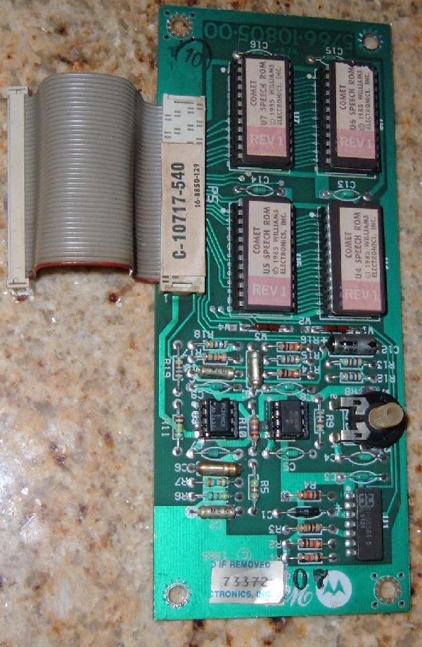
|
System 11/11a/11b Sound Problems.
On system11 games prior to the "C" series (sys11, sys11a, sys11b),
there are actually two different sound sections. The background sounds
are generated by a separate board (located just above the CPU board),
and the speech and game sound generated by a 6802 (u24), 6821 (u9),
6116 memory (u23), sound amplifier TDA2002 (u1), D/A converter (u2), and one or
two sound EPROMs u21/u22. The u21 sound EMPROM is the main sound code,
with u22 as data.
If you go into Diagnostics you will see there are two different sound tests.
Usually the first sound test ("music" test) is the background songs, and this is usually
generated by the separate sound board. But two diagnostic tests further is the "sound" test,
which is generated by the sound 6802 processor on the CPU board.
This is important to know as you don't want to try and fix a sound section that is
really working! I know, it's confusing, but this is how Williams did it... Well at
least until system11c, when the CPU board's sound section is not even populated,
and all sounds (background and game sounds/speech) are handled by a separate sound board.
If the Diagnostic sound test does not produce any sounds, the CPU board's 6802 sound section
has some sort of issue. The best way to diagnose this is to use
Leon's sound Test EPROM which is formated for a 27128 EPROM.
Note this EPROM also works on system9 sound sections too.
Note on the later system11b games if the board has no connector at 1j15 (speaker connector),
you will need to solder a speaker directly at the holes that normally have the connector pins.
Or install a connector there to use for testing with a speaker. Pins 1/2 and pins 3/4 are the
speaker connections. And of course the Leon test EPROM should be installed at u21.
Before powering up the board, replace the normal game ROMs at u26/u27 to avoid conflicts with the
running sound Leon test program, and install the Leon sound EPROM at u21.
Power up the CPU board as you would normally do with either the game's power supply or an
external power supply at connector 1j17 using +5 and +12 volts (1j17 is the only connector needed.)
Now check if the Leon sound test ROM is running at 6802 chip u24 pin15.
The signal there should be is constantly changing from 0 to 5 volts about every second. If this is not happening,
the program is not running. If the program is not running, you need to do the same
sorts of checks you do for the Leon main program.... Like check the basic signals coming to the CPU 6802 u24.
This includes the clock (pin37/pin39) and reset (pin40 which should be hight). These are the same as
the ones at the "normal" 6802 cpu at u15, so you can use that for comparison.
These signals must be Ok or the Leon sound test code will not run.
If the test is not not running a good first step is to change the 6802/6808 at u24.
Assuming the Leon program is running, test the
output pins of the u9 PIA pins 10 to 17. These should "dance" between 0 and 5 volts about once a second.
Now u9 pins 2 to 9 will not move as they are held at 0 volts by a direct connection to the outputs
of PIA u10. If the u9 pins 10 to 17 do not move, check first the selection signal of the
PIA u9 pin 23, there needs to be a pulse there. If Ok change the PIA u9 chip. If not check the selection
chip at u8 74ls139. Inputs are at pins 1,2,3 and you need pulses at all three pins. The output is at pin 4.
Only pin 4 can be at 0 volt while all others have to be a steady 5v. If pins 1,2,3 is at
0 volts, the input is bad. If pin 1,2,3 stay at 0 or 5 volts, the u8 chip is bad.
After the u9 PIA pins 10 to 17 are "dancing" (signifying the Leon test code is running and the PIA sound chip is good),
now it's time to check the sound RAM memory chip 6116/2016 at u23. With the board booted with the Leon sound
EPROM installed at u21 and the sound PIA u9 pins 10 to 17 "dancing",
push the "sound" switch once (the top most switch directly below chip u15 on the left side of the CPU board.)
The outputs of the PIA come to an halt for a short moment, and the pulsing PIA u9 outputs will
stop while the Leon test program checks the u23 RAM. If all is good, the u9 PIA outputs will start
"dancing" again. This means the 6116 RAM u23 memory is good. If the u9 PIA outputs pin 10-17 do not
restart "dancing", that means the memory test is running continuously with no exit. Meaning there's a RAM problem.
Check the signals at the memory chip (address/data lines.)
If the signals are ok, replace the 6116/2016 RAM u23 memory chip, and re-run Leons memory check.
At this point let's assume your PIA u9 is working and the 2016/6116 u23 RAM tested good.
We now can proceed to check the amplifier and D/A (digital/analog) circuitry.
To produce some sound, and test both these devices, we need +12volts and -12volt.
Up to this point you did not need a separate +12 and -12 volt power supply.
But the TDA2002 sound amplifier requires these voltage to make sound.
You can use an old PC power supply for these two voltages connected at 1j17.
- +12v at 1j17 pin 9
- -12v at 1j17 pin 8
- Speaker (8 ohms) at 1j15 pins 1 and 4
- No need for a volume pot, just tie 1j16 pins 1 and 2 together.
At power up if all is Ok you should hear this diagnostic test sound.
Sound like a rapid heart-beat, as that is the Leon chip "dancing" transistion from 0 to 5 volts.
If you are not getting this sound, first the TDA2002 amplifier.
Touch with your finger connector 1j16 pin2. A loud hum should be the result.
If not replace the amplifier u1 (TDA2002). If the amplifier is ok and still no sound
replace the D/A converter at U2. Note the D/A converter is a rare and expensive chip,
so let's hope that's not your problem...
At this point you should have a working sound section on your system11/a/b CPU board.
System 11 Sound Upgrades.
System11 games do not have great sound or speech.
To make the most of what system11 games do have,
upgrading the speakers is recommended. There are
pre-canned packages available from
pinballpro.com.
But I prefer to come up with my own sound configuration.
Most System11 games have a total of three speakers.
In the backbox area there is one small and one oblong speaker.
The small speaker is a 3 1/2" speaker, and the
the oblong speaker is a 4"x10" model. Oblong speakers
don't sound good compared to round speakers. Also the
3 1/2" speaker is pitful at best. A better approach is
to use two like-sized speakers in this area. The easiest
method is to use two 4" speakers instead of the 3 1/2" and
4"x10" speakers. The two 4" speakers can be mounted in the
same area as the original 4x10 speaker
without permanently modify the speaker
panel. Two of the original four mounting
screws can be used for the two new 4" speakers.
Then use two 1/4" drive screws for the other
two speaker mounts (each speaker gets two mounting
screws). Abondone the 3.5" speaker grill hole
as it is not needed (and too small).
The replacement 4" speakers must be 4 ohms each.
These can be easily found on ebay or at a car audio store
for a nominal price. Get "two-way" coaxial speakers
that are rated for 25 watts RMS or higher. Just be
careful that the interior coaxial cone does not
perturd beyond the main speaker's cone. If it does,
spacers will need to be used so the cone does not touch
the speaker grill when the new speakers are bolted in place.
Two 4" speakers replace the original 4"x10" oblong speaker and the 3.5" speaker
in a Banzai Run upper panel.
|
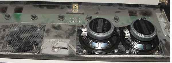
|
The bottom cabinet speaker is a 6.5" speaker.
Again find a good replacement, but this speaker
must be 8 ohms. Coaxial two-way speakers are best,
but any 25 watt RMS speaker should be far better
than the stock Williams speaker.
Speaker Hum.
If the game has a lot of hum while in attract
mode, there are a couple things to check. First
make sure all the circuit boards are screws down
to the metal ground plane in the backbox. A lot of
times the boards are loose, which doesn't help
the ground connection.
Next replace cap C8 on the power supply. This little cap
filters the supply to the IC1 voltage regulator (47uF).
Ripple on the 5V supply from this cap being bad can
cause hum. You can use another 47mfd cap for C8, or
go as high as 100mfd. Cap C7 (100mfd) is also a good thing to
replace on the power supply while you're doing this.
(These two caps get baked by the large heat sink,
and helps with low +5 volts or even resets.)
Loose of Speech after Several Minutes.
Example: Pinbot that loses speech after being on for 15 minutes.
Speech will not return until the game is power cycled.
Other sounds are fine, just the speech. When speech disappears
can put it in the sound test and
sounds from 1 through 5 are fine, 6 and 7 are out. Replaced
some caps on the sound board but did not help.
Solution: Bad 55536 chip on the CPU board, this chip handles
the speech calls.
3q. When thing don't work: Miscellaneous Oddities
Problem: In attract mode, the pop bumper coil on my F-14 behaves normally (did not fire or energize).
Once a game was started or test mode entered, the coil would fire and stay energized.
In attract mode, the coil could be fired by hitting the pop bumper skirt switch
(this is NOT normal behaviour, and the others pop bumpers did not work this way)!
Grounding the metal tab of the Q69 TIP122 transistor while the game was in attract
mode energized the coil and released it (properly).
Answer: A close look at the 7402 chip at U50 (which is the controlling TTL for this coil)
revealed that pins 5 and 6 where shorted together. This was caused by a solder splash from a previous
repair. Removing this short fixed the problem!
I turn my system 11 game on, and the score displays will only show 0's and
X's in the middle of them.
Problem: the game thinks you have "slammed" it.
Answer: there is a slam switch inside the coin door, just above the
coin door lock. This switch should be normally open. If this switch
is shorted or bent closed, you will have this problem. Often people
will accidentally bend this switch when putting credits on the game
(a good reason to have the game set on free play!). If the switch is not
shorted closed, the switch matrix could also be damaged, as the slam
switch is part of the switch matrix. See the
Switch Matrix
section of this guide for info on fixing that.
A system 11 game coil is always energized.
Problem: "I have a system 11 game with solenoid problems. I have replaced
the TIP122 transistor, the associated pre-driver transistor, the 7408 chip,
and even the 6821 PIA. But nothing keeps the solenoid from staying energized."
Answer: some 50 volt coils are driven by a TIP36 transistor on the Auxiliary power driver
board. If the TIP36 is shorted, the coil will stay energized (regardless of
what you replaced further up the electronic river).
"When I turn my Fire! game on, the score displays would flash quickly at a
high brightness, and the speakers would be noisy, but the game does nothing more."
Problem: the CPU board has a blanking circuit problem. The job of the blanking
circuit is to shut down the score displays, solenoids and lamp circuits if there
is a problem on the CPU. This safety circuit also protects other circuits during
power-on if there is a problem.
Answer: there were two failed components, a 555 timer chip at U43 and a bad
2N4403 transistor at Q50.
To test the blanking circuit for proper operation, check U20 pin 2 or U43 pin 3
at power-on, using a logic probe. You should get an initial LO for a few seconds,
followed by a continuous HI after the game has booted.
All score displays are out, game will start but flippers and
ball eject do not work.
While the game was being played (when it worked) the displays began
acting strangely then the game died. Any further attempts to start a game
resulted in above problems.
Answer: Examining the display board discovered a glob of
flux on U11 (4050 hex buffer) shorting pins 14 and 15 together. Using the
schematics and wiring diagrams was able to trace those pins back to the CPU
board. The short killed U51 (PIA 6821) on the CPU board. Removed U51 (6821), added machine pin socket,
and replaced it with a new 6821 PIA.
"No Sound on my Pinbot."
Problem: The sound on the Pinbot just suddenly died. The amplifier section seems
to work, because when the volume control is turned, you can hear the scratching
sound coming from the speakers. Also when the sound test button is pressed on the
CPU board, you can faintly hear the sounds.
Answer: No -12 volts DC, which is used for the sound. In this case it ended
up being the bridge rectifier that converted the 12 volts AC to DC voltage
that had failed.
When the flipper button is pressed, the game resets. When the ball hits the slingshot,
the game tilts.
Problem: This is a switch matrix problem. The low voltage (high score) switch on the flippers
and the slingshot scoring switch are triggering other switches in the switch matrix.
Answer: First I would suggest looking for a bad, missing or mis-wired switch diode. But
in reality this was not the problem. A switch matrix column transistor (2N3904) was
bad, as was the switch matrix column resistor network SR15.
The CPU software for Road Kings on the Williams web site does not seem to work.
Answer: Indeed the EPROM software for Road Kings on the Williams web site is bad. For
working software, click here for working EPROM files.
On My F-14, I need a new rubber belt to drive the rotating beacon lights. Where
can I get this?
Answer: This rubber drive belt is available from any local John Deere tractor store!
Just ask for part number H85996, cost is about $2.00.
Just got a F14 and the Flippers don't work, and neither does
the Lock Kickout, but the fuses are OK. What is the problem?
Answer: Check flipper power supply board (long thin board on far right inside
backbox). On games Big Guns and later, check the Auxiliary power driver
board (right side of backbox). These boards supply 50 volt power to flipper coils
and some of the other playfield coils.
There is also a fuse for the 50 volts on the associated power supply board, and a
fuse mounted off-board on the metal plate on the backbox below the boards.
Earthshaker booted and worked perfectly for about an hour. Then, as the
game was thoroughly warmed up, the displays started to "lose" digits
one at a time until the displays were blank. The solenoids also
stopped working as did the background sounds. It would coin up and
start a game, but when a solenoid was supposed to fire only a faint
buzzing could be heard.
Answer: Fixed the game by checking the board with a logic probe and found that
the blanking signal was pulsing rapidly instead of staying low. Since
it was pulsing, the blanking LED appeared to be "on" to the naked eye,
when it was actually blinking very fast so the issue was not apparent.
The game would work perfectly just by jumping pin 1
of u55 to +5 volts. So, obviously the problem was actually
with the blanking circuit (instead of the blanking signal being a
symptom of another problem). I replaced the 555 timer and 2n4403
transistor in the blanking circuit and let the game warm up, but no
change. After a little more investigation with the logic probe and
DMM, I began to suspect c58 (the 1uF electrolytic) which
corrected the problem.
Rollergame's magnet does not always catch the ball.
Answer: If Rollergames sometimes just doesn't catch the ball for
the "Flip, Don't Flip" part of the game, there are a few things to
know. First a 2n4401 on the CPU board drives a TIP120 (or TIP102)
again on the CPU board. This is turn goes to a TIP36 mounted under
the playfield on a small board. Besides usual problems like connector
issues (replace with crimped trifurcon pins and make sure none of the
male header pins have cracked solder joints),
the ground connections from the under playfield board often
has issues (look at the board traces). A good idea is to double-up this ground connection from
the under playfield board. Another thing that is helpful is to
re-grind the playfield magnet core into a golf tee shape (this will
really help with ball catches). Lastly, though rare, the
4N25 opto couplers on the interconnect board (which senses the
flipper switches) could be bad.
|