3c. When Things Don't Work: Diagnostics (Display test,
Lamp test, Solenoid test, Switch test, Sound test)
Where Bally took the approach that the boot-up diagnostics were
very important and game diagnostics were not, Williams took the opposite
approach that boot-up diagnostics were *not* important but
game diagnostics were! Hence where 1977-1985 Bally games
don't really have a lamp, display, coil or switch test,
Williams system3 to system7 games do have good versions
of these tests (assuming that the game in question will
boot up properly!)
System4 to System7 Diagnostics.
The diagnostic firmware is located in the "Flipper ROMs"
at IC20 and IC17. Remember our previous discussion of this,
system4 uses yellow flipper ROMs,
system6 uses green flipper ROMs, and system7 uses blue flipper ROMs.
System3 (white flipper ROMs) diagnostics are different to
access, so see the section on that below.
But the system4 to system7 diagnostics are pretty easy to use
following these instructions. These diagnostics will
test the score displays, the lamp matrix, the switch matrix
(and on system7 a separate test for sound).
For system4 to system7 games,
to use the internal game diagnostics,
the game will need to boot up into attract mode.
To access the switch diagnostics, there are a pair of
switches inside the coin door that need to be accessed.
Here are the steps used to access the diagnostics on system4 to system7
games:
- Turn the game on and allow it to go into attract mode.
- With the coin door open,
press the coin door Auto-up/Manual switch into the manual position.
- Press the coin door Advance button. On system3 to system6,
the score displays should go blank. On system7, all the score displays
will light up with "0000000".
- Press the coin door Auto-up/Manual switch into the auto-up position.
- System3 to System6 only: Press the coin door Advance button.
- The game should now go into the first test, which is
the SCORE DISPLAY test. All the score displays (including the credit/ball-in-play)
should cycle from "000000" to "999999". If a particular display
does not work or shows the wrong values, go to the
score display repair section.
- System 7 only: Press the Advance button again to pass over the
score display test. This will go
to test 00, as indicated in the credit score display, which is
the SOUND test. Each sound number will be displayed in the ball-in-play
window, and played by the sound board. If a sound is missing or there
is no sound, go to the
sound repair section.
- Press the Advance button again to pass over the previous test.
This will go to test 01,
as indicated in the credit score display, which
is the LAMP MATRIX test. All the CPU controlled lamps
will cycle on and off at once. If a number of lamps are not working
(and it's not burnt out bulbs), go to the
lamp matrix repair section for more details.
- Press the Advance button again to pass over the lamp test.
This will go to test 02,
as indicated in the credit score display, which
is the SOLENOID test, and each solenoid from 01 to 22 (as
indicated in the ball-in-play display) will be exercised.
Remember on system3 to system6, coils 9-13 are usually sound drivers.
System7 games will also test coil numbers 23,24,25
(25 is the flipper relay, but 23/24 are unused in
all system7 games). If a particular coil or group of coils does not work, go to the
coil repair section.
Note for the special solenoids (coils 17 to 22), be sure to
test these solenoids using the playfield trigger switches too.
Just because a special solenoids 17 to 22 work in diagnostics does *not* mean
they work in the game, as these coils have two distinct hardware
triggers.
- Press the Advance button again to pass over the solenoid test.
This will go to test 03,
as indicated in the credit score display, which
is the SWITCH MATRIX test.
On system3 to system6,
the ball-in-play display will show the last read (closed) switch number.
On system7 only, if there are multiple switches closed, the switch
numbers will alternate in the ball-in-play display.
If a switch or number
of switches do not work, go to the
switch matrix repair section.
- Press the Advance button again to pass over the switch matrix test.
This will go to test 04,
as indicated in the credit score display, which
is the AUDITS. The ball-in-play display will show the audit
number, and the player1 score display will show the audit value.
The Advance button can be pressed to move
from audit to audit. Check the game manual for a list of
audit numbers and what they represent.
To exit the diagnostics or audits, turn the game off and back on.
On system3 to system6 games, after accessing the last audit number,
pressing Advance will wrap the audits back to audit number 01. On
system7 games, after accessing the last audit number, pressing Advance
will put the game back into attract mode.
System3 (White Flipper ROM) Diagnostics.
On system3 (white flipper ROM) games, getting to the
diagnostics is a bit tricky (sometimes it will frustrate
me so much, I end up putting yellow or green flipper ROMs and an
appropriate Game ROM temporarily in the CPU board so I can easily get
to the diagnostics!)
Once you have done it a few times and understand
the timing, it's a lot easier.
Having good batteries in the CPU board with system3 white flipper ROMs
is also very helpful. No batteries and a system3 ROM CPU board acts strange
(compared to system4 to system7 games),
and is more difficult to get into diagnostics. With no batteries the
game will boot into audit mode (often "01 04" or "18 04" on the score ball/credit display,
and if the manual-down/auto-up switch is in the auto-up position,
it will auto-increment the first number pair). Also white flipper ROM
diagnostics run slower than yellow and newer flipper ROM diagnostics.
You will notice this especially in the solenoid and switch test
modes, as it seems the game is almost in slow motion in it's reactions,
compared to later games.
Here are the system3 white flipper ROM diagnostic instructions:
- With the game in attract (game over) mode,
set the coin door Auto-up/Manual-down switch to Manual-down.
- With the coin door open, press the Advance button once.
This should show audit #18 in the credit display
("18 04" in the credit/match displays).
- Press the Auto-up/Manual-down switch to Auto-Up.
The audits will now start auto-incrementing, counting up,
automatically showing the audits.
- Press the Advance button twice, with about 1/2 second of time
between the two button presses. Yea I know, this sounds very
precise, but it must be done this way! This is where the "timing" comes
in, and practice is the only real way to get this.
If done correctly, the score displays should now be blank.
If the two switch presses are done too fast or too slow,
the game will return to attract mode,
and you'll have to start over at step one above.
- Press Advance once again, and the game should now go into the first test, which is
the SCORE DISPLAY test. All the score displays (including the credit/ball-in-play)
should cycle from "000000" to "999999". If a particular display
does not work or shows the wrong values, go to the
score display repair section.
- Press the Advance button again to pass over the score display test.
This will go to test 01,
as indicated in the match (ball in play) display, which
is the LAMP MATRIX test. All the CPU controlled lamps
will cycle on and off at once. If a number of lamps are not working
(and it's not burnt out bulbs), go to the
lamp matrix repair section for more details.
- Press the Advance button again to pass over the lamp test.
This will go to test 02,
as indicated in the match/ball in play display, which
is the SOLENOID test, and each solenoid from 01 to 22 (as
indicated in the credit display) will be exercised.
Remember often system3 games coils 9-13 are sound drivers.
If a particular coil or group of coils does not work, go to the
coil repair section.
Note for the special solenoids (coils 17 to 22), be sure to
test these solenoids using the playfield trigger switches too.
Just because a special solenoids 17 to 22 work in diagnostics does *not* mean
they work in the game, as these coils have two distinct hardware
triggers.
- Press the Advance button again to pass over the solenoid test.
This will go to test 03,
as indicated in the match/ball in play display, which
is the SWITCH MATRIX test. The credit display will show the last read (closed)
switch. If there are multiple switches closed, the switch
numbers will *not* alternate in the credit display. If a switch or number
of switches do not work, go to the
switch matrix repair section.
- Press the Advance button again to pass over the switch matrix test.
This will go to test 04,
as indicated in the match/ball in play display, which
is the AUDITS. The credit display will show the audit
number, and the player1 score display will show the audit value.
The Advance button can be pressed to move
from audit to audit. Check the game manual for a list of
audit numbers and what they represent.
To exit the diagnostics or audits, turn the game off and back on.
On system3 to system6 games, after accessing the last audit number,
pressing Advance will wrap the audits back to audit number 01.
Pulse Lengths in Diagnostics.
The length of time a coil is "pulsed" in diagnostics may not be long
enough to make the device "dance". That is for example, in game mode, it takes
a fairly long pulse to reset a drop target bank. But in diagnostics,
usually shorter pulses are used. So if that drop target bank does not
reset in diagnostic mode, don't worry about! Wait until game play
and test the coil there before working on something that isn't really
broken.
Diagnostics Not Working.
If a CPU board connector 1J4 is not attached, the coin door buttons
for diagnostics will not work. This connector is the second from
the left across the top edge of the CPU board. Cracked header pins
on this 1J4 connector can also cause problems. And if the adjustments/diagnostics
just keep rolling (even though the coin door switches are not shorted or
being pressed) after entering diagnostics, CPU chip IC5 (74ls02) could be bad.
3d. Before Turning the Game On: Random Lockups
& Resets: What Causes Them & Testing for Them.
Random lock-ups and resets includes the game shutting down during
play or attract mode, or it just goes crazy making random sounds and
scoring invisible points. Another commonly seen reset is if
both cabinet flipper buttons are pressed during game mode,
the game ends and goes into "attract" mode. If the backglass is
removed and this repeated, you will see the game is actually
rebooting (note the LEDs flash or on system7 the "0" code flashed
on the segmented LED).
These problems are usually caused by either one of three problems:
power supply ripple, weak bridge rectifier, connector failure, or a bad coil diode.
For example, if the game resets when pressing one or both flipper
buttons, then there may be a broken or missing diode on a flipper coil.
A broken diode allows the voltage to reverse back to the power supply.
This is caused by the collapse of the
coil's magnetic field (interestingly, a 30 volt coil will produce
a 60 volt back "spike"). This completely freaks out the power
supply, causing the game to reset. Replacing the coil's diode
usually fixes this problem.
Game Resets.
If the game resets when pressing one or both flipper
buttons, then there may be a broken or missing diode on a flipper coil.
A "reset" is classified as this:
If both cabinet flipper buttons are pressed during game mode,
the game ends and goes into "attract" mode. If the backglass is
removed and this repeated, you will see the game is actually
rebooting (note the LEDs flash or on system7 the "0" code flashed
on the segmented LED).
Check the flipper coil diodes first as it's the easiest thing to check. Gently tug
on the flipper coil's diode(s) to see if they are cracked or not
properly soldered to the coil's lugs. If no problems are seen with
the flipper diodes, next check the power supply filter capacitor
for AC ripple. With the game on put the DMM leads across the
power supply's large filter cap. Less than .200 volts AC should be seen on
system7 (or system9/11), and less than .300 volts AC on system3-6.
If more than that is seen, replace the filter cap. On System3-6 games with more
than two flippers, use a 15,000 MFD filter cap. On system3-6 games
with two flippers, a 10,000 MFD filter cap should work fine. On system7
(or system9/11) I recommend a 15,000 MFD filter cap.
Also on system7 (and system9 and system11) games, often the power supply's
5/12 volt bridge rectifier needs to be replaced.
I install a new 35 amp 200 volt bridge rectifier. Replacing
the bridge and the filter cap will usually
fix a flipper-envolked reset problem.
Game Lock-Ups: a Summary of What Could be Wrong.
At this point, all the circuit board updates and modifications
should have been performed. If the game boots, it is now time to
test for random resets and lock ups.
If a reset/lockup happens, it is usually related to the
following:
- Bad CPU/Driver 40 pin interboard connector.
- Bad CPU/Driver board chip sockets ("Scanbe").
- Bad board connectors and cracked solder header pin solder joints.
- Bad 1J2 CPU board power connector.
- Bad +5 volt filter capacitor.
- Bad bridge rectifier (system7).
- Missing/broken diodes on a coil(s).
- Problem with the switch matrix.
The first thing to notice is if the problem occurs only during game play, or
just while the game is in attract mode (in both circumstances).
The second thing to notice is does the game reset, or does it lock up
(a lock up is defined as
the two CPU board LEDs are on, or there's a "0" on the 7-digit System7 CPU board display).
If the game *resets* during play, this is usually a power related problem
(bad coil diode, bad +5 volt filter capacitor, or problem with the switch matrix).
See above for solutions to that.
If the game *locks-up* during play or in attract (game over) mode,
the problem is usually connector related.
Games that reset while in attract mode usually have
connector related problems or low line voltage (below 115 volts).
Testing for Resets.
To narrow this down to a intermittent connection (points 1,2,3,4 above),
or to a +5 volt filter cap, missing diode or switch problem, try the following.
With the game off, remove fuses F2 and F3 from the power supply
(solenoid and lamp matrix fuses).
Now turn the game on and go into self test. Put the
game in the "digits test" (which conveniently is the first self test),
so that the displays are cycling all the
different score display numbers. Now just walk away for a couple of hours or more
(letting this test run overnight works well).
Upon returning, if the score digits are not cycling, then the game
reset without any game play occuring. This means there is
an intermittent problem (points 1,2,3,4 above). If the game
is still in the digits test, then the reset problem is probably
a bad +5/12 volt filter capacitor, broken coil diode, or a switch matrix problem.
Bad 5/12 volt Filter Cap.
A bad +5/12 volt filter capacitor will really only show its ugly
head when the game is played. The coils turning on and off
forces the +5 vdc filter cap to work harder. If it's bad,
it should show pretty quickly in game play. Likewise for
bad coil diodes, and switch matrix problems (though often
switch matrix problems can be duplicated in the diagnostics
switch matrix test).
Missing or Broken Coil Diode.
A missing or broken coil diode (especially a missing diode
on any flipper coil) can really cause strange game behavior and resets.
For example, a missing/broken flipper coil diode can cause the
game to reset if one or both flipper buttons are pressed.
A broken diode on another type of coil can cause a reset just
when that device is used.
For example, a reader reported that the flippers caused the game to lock up
on his Firepower.
He went to the game's coil test, and noticed the middle
right multiball saucer solenoid was not firing. He replaced that coil's
diode (which fixed the saucer coil),
and the flippers no longer caused the game to lock up.
Be sure there is a 1N4004 on *every* coil. A good way to test
for a broken/cracked diode is to try grabbing the diode with
your thumb and forefinger, and giving it a gentle tug. Often
the body or lead of a diode can crack, and this will identify
it. If there's any doubt though, just replace that diode with
a new 1N4004 diode. They are inexpensive, and it's an easy
job. Just remember that the banded side of the diode goes
to the power lug/wire on the coil (the power wire is usually
the thicker wire, and is "daisy chained" from one coil to another).
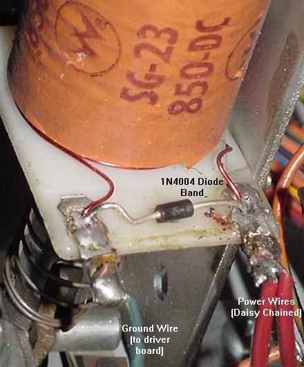
The 1N4004 coil diode mounted on a Firepower slingshot,
showing the proper orientation of the diode and power wires.
|
Diodes can be tested with a DMM, but frankly it's not
worth it, as one lead of the diode needs to be disconnected from
the coil for a good test. To go through the work of removing
one end of the diode, it's about as easy to just replace the
questionable diode instead. But here's how to test a coil diode:
- Turn the game off.
- Unsolder or cut one end of the diode from the coil.
- Use a DMM set to the diode function.
- Put the black DMM lead on the banded side of the diode.
- Put the red DMM lead on the NON-banded side of the diode.
- .4 to .6 volts should be seen.
- Reverse the DMM leads, and a null reading should be seen.
- If these values are not seen, replace the diode with a
new 1N4004 diode.
The Switch Matrix and Resets.
If there is a short in the switch matrix a bad diode on a playfield
switch, or a mis-wired playfield switch,
this can cause resets and strange game behavior too. For example,
column one of all system3 to system7 games have the tilt and slam tilt
switches. If another switch gets shorted in the same row or column
as a tilt switch, strange game behavior can occur during game play
as other switches are activiated in that row or column.
Summary.
The only way to fix the listed things above is *replacement*
of parts! New 40 pin connectors between the driver and CPU
boards, new chip sockets to replace the old "Scanbe" sockets,
new power connector at CPU board 1J2, and new
+5 volt filter capacitor.
And while the CPU and driver boards are out, might as
well resolder all the .156" male Molex connector pins on the
edges of the boards, as these often crack.
3e. When Things Don't Work: Non-Working or Locked-on
Coils/Flashlamps
Introduction.
In a working game,
the first thing to remember on all coils and flashlamps
is power is *alway* present at all coils/flashlamps. All these devices
are waiting for is the backbox driver board to complete the
their power circuit to ground, causing the coil or flashlamp to energize.
Essentially the driver board is a big computer controlled grounding
plane. Through the game ROM program, the CPU, and the PIAs (Peripheral
Interface Adaptors), the game can control
which driver board transistor can "sink" a ground, and hence complete
a particular coil's power path (causing the coil/flashlamp
to energize for a short period of time).
The way the driving logic works is as so: the CPU, which is
running the game ROM program, wants to energize a coil. It
tells the a PIA (Peripheral Interface Adaptor)
to turn on the appropriate coil.
This in turn drives a 7408/7402 chip, which then turns on a small
"pre-driver" 2N4401 transistor. So far this is all done with
"logic level" 5 volts. Then the pre-driver transistor turns on
a much bigger TIP120/TIP102 transistor. This final link in the
chain is what ultimately completes the coil's path to ground,
causing the 28 volt coil to energize momentarily.
A potential problem with this system is if ANY part in the
chain shorts, everything else down the chain turns on, and
a coil locks-on. Typically this is last link in the chain,
the TIP120/TIP102 driver transistor, becoming "shorted" internally
(because this device is in direct line with the 28 volt solenoid
voltage, where the other devices are "buffered" from this voltage).
But it could be
any of the other parts too! (the 2N4401 pre-driver transistor,
the 7408/7402 chip, or the PIA chip!) It could even be ALL these
devices short on!
So instead of
the CPU controlling the driver transistor (and hence
its associated coil/flashlamp), the coil/flashlamp becomes
lock-on (permanently energized), because the path to ground
is shorted inside one or many of the controlling devices.
So if a coil (or several coils) or flashlamps are locked-on,
the TIP120/TIP102 is at minimum is usually the cause.
But the big problem is if the TIP120/TIP102
driver transistor shorts, sometimes the "backlash" can ruin
the parts behind it (2N4401, 7408/7402, PIA) that control
the transistor.
All Coils Locked on - the Blanking Signal and Other Causes.
In Williams system3 to system7 games, there's another reason
a bunch of coils/flashlamps would be locked on. That would be
if the blanking signal is not high, allowing all the coils
to energize at power-on and stay energized. We really won't talk
too much about that condition
in this section, as that's really a failed CPU/Driver board issue
(and not a failed coil/transistor). See the
Dead CPU section for more info on that subject.
Note if only a one or a few coils are energizing at power on,
then there is probably a shorted driver board
transistors, and NOT a problem with the blanking signal.
The blanking signal is a "flag" from the CPU board to the driver
board. If the blanking signal is high (4 volts or greater), the
CPU board is saying to the driver board, "Hey! I'm working and ready!"
If the blanking signal does not go high, the driver board does not
"wake up", and often this means all the game's coils will energize!
A low blanking signal can signify there is a CPU board problem.
But there could also be a high CPU board blanking signal that
gets "lost" while going over the 40 pin interboard connector,
leading to the driver board!
The blanking circuit should go HIGH very soon after the machine is
powered-on (almost instantaneous). When the blanking signal is LOW,
it allows all the coils to energize automatically.
In general, the blanking circuit reading can be taken at pin
37 of the 40-pin inter-board connector (4th pin from the left),
and should be at least 4 volts. This is
where the blanking signal goes from the CPU to the driver board.
Aside from the blanking system, I have also seen other conditions where
all the coils energize at game power-on (this was a Williams Time Warp.) Of course you'll
hear a big "thud" as the coils all pull at power-on, until the power supply
solenoid fuse blows. It was a strange condition as even the
flipper relay would stay energized (flippers worked in game over mode),
and the sound board was making noise too (sound board inputs are controlled
by the driver board on system3-6 games.) A very strange occurance
indeed. In this situation the game did completely boot
(score displays showing high score, playfield lamps
"dancing" in attract mode.) So it was no surprize that pin37 of the interconnector
was high (signifying the blanking signal was good.) But what
caused this? Turns out the problem was a bad driver board
solenoid IC5 PIA 6821. Replacing this 40 pin chip fixed the problem.
I really was second guessing myself too, as using a DMM set to
diode function (red lead to ground) and testing each pin of
the PIA with the driver board removed did not show any issues
(everything tested .4 to .6). But obviously that's not
a great way to test a PIA chip (though it can show direct
shorts.)
Solenoid Power Circuit.
The 28 volt solenoid circuit consists of a bridge rectifier
mounted on the backbox.
Like the lamp rectifier, its a 35amp, 400 volt bridge rectifier. After that,
the power goes to the power supply board, and thru a 47volt varistor
used to protect the coils from a voltage spike (if the voltage goes above 47 volts,
the MOV varistor shorts, which will blow the main solenoid fuse).
There is also a 100 mfd filter capacitor.
The driver board driver transistors are the most probable source of solenoid
problems. But an easy first test is to measure the voltage at connector
3J3 pins 6-9 on the power supply board,
which should show about 28 volts DC. If there is no voltage, check the solenoid
fuse F2. If there is a lower voltage, the backbox mounted bridge rectifier
has probably partially failed. If the voltage is higher than 28 volts, don't worry
about it (as long as it's not more than 47 volts!) The "unloaded" system should
measure higher than the "loaded" 28 volts DC.
Flipper Power Circuit and the Flipper Relay.
Next to the GI circuit, this is the simplest circuit in the game.
The only electronic part is the bridge rectifier that is shared with the
solenoid circuit (discussed above). Note the flippers do not use a filter
capacitor. On System3 and System4 games,
28 volts DC goes directly to the flippers from the backbox bridge rectifier,
with the flipper fuse located under the playfield. Starting with Flash (System6),
the flipper voltage is "passed through" the Power Supply board, with fuse F4
now protecting the flipper coil circuit, instead of a playfield mounted flipper
fuse.
Remember later system7 games (Firepower2 and later) have a separate 50 volt
power supply board for the 50 volt flippers. This upgraded flipper voltage
was increased from 28 to 50 volts to give the flippers a bit more snap.
But the rest of the coils in the game are still 28 volts.
If the flipper coils don't work or don't shut off after a games ends,
there may be something wrong with the driver board mounted Z1 flipper
relay (or the transistor and other components
that drive the flipper relay, and these part number are the same for all system3
to system7 games). This is kind of a last thing to check,
as flipper relay problems are not common. Test the 2N4401 transistor Q13 (positioned
right next to the relay) with the testing procedures described in the
Transistor Testing section of this guide.
Also the 7402 chip at IC8, which drives transistor Q13 could be bad.
There have even been reports of resistors R27 (4.7k 1/4 watt) and
R26 (10k 1/4 watt) being bad, in addition to diode D1 (1N4001).
Lastly test the flipper relay itself, as the relay does go bad
(the driver board will need to be removed to do this). A 9 volt
battery can be used on the relay's coil lugs (the two isolated
lugs from the other 12). Use the battery and
check if the relay
actually pulls its armature in and out (it should click nicely).
If a replacement relay is needed,
this relay is a 4PDT (4 pole double throw), 40 ohm, 6 volt relay,
and a suitable replacement can be found at Mouser.com, part #528-7810-1
(MagneCraft #W78CSX-1, $5.50).
Don't Forget the Grounding Strap.
In the backbox behind the backglass, there is a ground wire/strap which
attaches to a wing nut. This ground strap is very important, and
must be connected. On many system3 to system7 games, some features
of the game won't work (or won't work properly) if it's not attached to the
wing nut and the wing nut tightened.
Also later games from Firepower on had an
additional white-with-red trace grounding wire coming from the
playfield that needs to be cinched under the wing nut along with
the braided ground wire.
Remove Fuses F2 and F3 When Doing Intial Testing.
Be careful when testing an unknown game. At power-on, some coil may lock on
and constantly
energize. This will burn both the coil and its driver transistor. Until
the CPU is working properly, it is wise to remove coil and lamp fuses F2
and F3 from power supply board to minimize problems.
The Coin Door Coin Lockout Coil.
On the coin door, there is a small relay sized coil known
as the "coin lockout coil". When a system3 to system7 game
is powered on, this coin lockout coil should always be energized!
Yes that's right, the associated driver board transistor should
always allow this coil to be "on", when the game is powered on.
When the coin lockout coil is de-energized, the game will reject
money. This is done so if some (dumb) player inserts money into
a powered-off game, their money is returned to the coin return shoot.
Basically if the game is on, the coin lockout coil is energized. It is
even energized when the game is in diagnostic mode (on most, but not
all system3-system7 games). Note on some games, if the game is set to
"free play" through the adjustments, the coin lockout coil will
de-energize when the game is on.
Coin lockout coils were done away with during system11 I believe.
Williams needed the transistor for other more important chores,
like playfield devices.
Could the coin lockout coil be blowing the solenoid fuse? Yes!
Since this coil is on *a lot*, it gets hot with time. The winding's
wire bakes off its insulation, making adjacent windings short
to each other. This reduces the resistance of the coin lockout
coil from it's normal (about) 80 ohm resistance, to be lower.
As a coil's resistance becomes lower, it draws more current,
and becomes hotter. As it becomes hotter, it burns more winding
insulation. It's a endless cycle until the coin lockout coil
burns up. When a coil's resistance gets below about 2.5 ohms, it
essentially becomes a "dead short", and this will blow the
solenoid fuse.
This coil can be tested - Just put a DMM set to resistance on the
coil lugs (with it's driver board
connector J9 removed to isolate the coil) and check the resistance.
It should be greater than 50 ohms. Note the driver board
transistor that controls the coin lockout coils is Q45
(bottom row, furthest to the right).
A good way to test this transistor
is using the game's internal diagnostics and testing coil number 16
(the coin lockout coil will be energized during all of diagnostics
on most system3-7 games,
but when coil number 16 is tested, this coil should cycle on and off).
Another way to test transistor 45
is with a DMM set to the diode function, and the game turned off
(as described below).
Some good advice is to disconnect the coin door's coin lockout
coil. This can be done by cutting the ground wire (wire going to the driver board)
from the coin lockout coil. Then modify the coin door mech
so the coin lockout coil is not needed (that
is, if using the game with coins). This modification is very easy
(involves bending or removing the coil trigger bar).
The problem with the coin lockout coil is it is old, and usually
near death, often BUZZES loudly, consumes power (higher operating
costs), and it only causes problems. And frankly, in a home
environment, it's not needed! Even if operating the
game for money, I would disconnect it (it's only a problem waiting
to happen). If a player doesn't notice the game is off,
and puts money in, that's their problem!
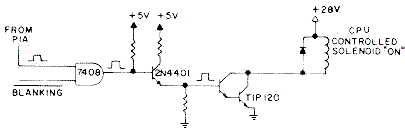
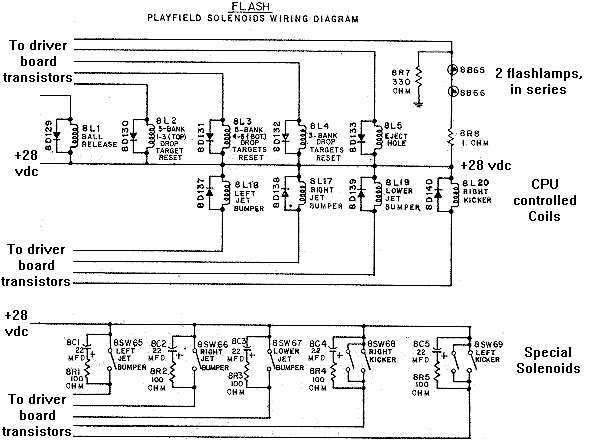
CPU Controlled Solenoids.
CPU controlled solenoids are obviously controlled only by the CPU,
and the game ROM program that the CPU is running. CPU controlled coils also
have a "one shot" type operation, with a percise energize time.
By "one shot" I mean if their controlling trigger switch gets
stuck on, the coil fires one time (one shot), de-energizes, and
stays de-energized. So a stuck playfield switch only makes the
device non-operational, opposed to locking the device on and letting
it burn. CPU controlled solenoids are numbered one to 16 in
the solenoid diagnostic test and schematics.
The 16 CPU controlled solenoids are program activated by
PIA IC5 via a 7408 chip and two transistors (2N4401 pre-driver and a
TIP120/TIP102 driver).
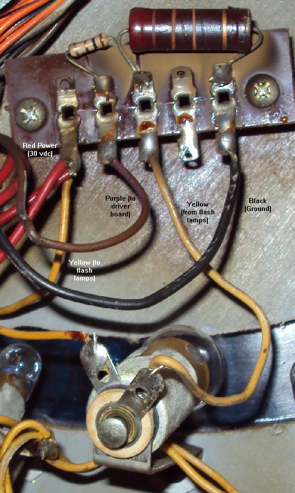
The system3-7 CPU controlled solenoid schematic.
|
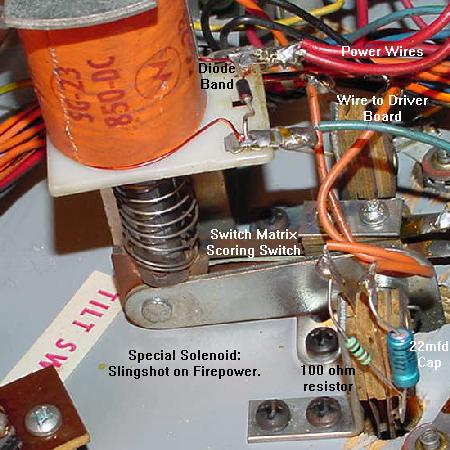
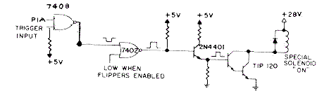
Special Solenoids.
Special solenoids on the other hand work differently than CPU controlled coils.
Special solenoids are used in pop bumpers and slingshot kickers, and since
they must act quickly, the CPU does not control them.
Closing of a special solenoid's playfield trigger switch
enables solenoid power directly through TTL (Transistor to Transistor)
chip logic and two transistor, without any processing by the CPU chip.
A second switch matrix switch is closed
when a special solenoid pulls in, which tells the CPU to score
the solenoid points (CPU controlled
solenoids do not need this second switch). Hence the special
solenoid trigger switches are not part of the switch matrix,
where the scoring switch is. Note
there are six special solenoids in the system3 to system7
driver board.
At the time,
it was felt that the clock speed of the CPU was not fast enough
to give quick acting pop bumpers and slingshot kickers, as the CPU was doing
other things like monitoring
the switch matrix and running the lamp matrix and score displays.
Note though two games, Time Warp and Stellar Wars, used five pop bumpers and
two slingshot kicker. Since there were only six special solenoids, something had
to give on these two games. In Stellar Wars, the lower right pop bumper was
a CPU controlled solenoid. On Time Warp both slingshot kickers
where CPU controlled solenoids.
But the story doesn't end there with Special solenoids. The
control of special solenoids on all system3 to system7 games
is directly through playfield control via the playfield trigger
switches. But interestingly, special solenoid can also be
controlled by the CPU too. This can be seen when running
the internal game diagnostics, and the game turns the special
solenoids on and off in the coil test. Because of these "dual trigger"
(two ways to turn on) functionality of the special solenoids,
these can be more problematic than the other 16 "CPU controlled"
coils on the game.
A special solenoid slingshot kicker on a Firepower. Note even this
coil uses a 1N4004 diode (with the banded end connected to the
power wire). In addition the playfield activition trigger switch
has a 22 mfd polarized cap and a 100 ohm resistor in series.
|
Special solenoids use a 7408 chip, a 7402 chip, and two transistors
(2N4401 pre-driver and a TIP120/TIP102 driver).
This is one more TTL circuit than the CPU controlled coils use.
A special solenoid operates if the playfield switch (through connector 2j13)
pulls one 7408 input low.
The other 7408 input can be pulled low by the CPU via a PIA (and this is what
is done in the diagnostic solenoid test). Then this goes to a 7402,
and then to the 2n4401, and finally to the TIP120 that sinks the coil's ground
(turning the coil 'on'.) So a special solenoid could work
in diagnostic test but not work in game mode (or vice versa). This confuses
a lot of people because the diagnostics show a coil a "working", yet when
playing the game the same coil does not respond.
In addition, right when a game is started, a special solenoid can
'lock on'. This is often due to a playfield switch being stuck closed.
But it can also be a problem with the 7408 or 7402 chip(s). If removing
driver board connector 2j13 (upper left corner) unlocks a stuck-on coil during game play,
then the problem is on the playfield. If the coil stays locked on
during game play with 2j13 removed, the problem is on the driver board
with either the 7408 or 7402 chip(s).
Also the the special solenoid playfield switch trigger has a 100 ohm
1/2 watt resistor and a 22 mfd 100 volt electroylic capacitor (the positive
lead connected to the resistor) in parallel to the switch. This is different
than CPU controlled coils that use a switch matrix switch to turn them on (switch
matrix switches only have a 1N4004 diode on the switch).
Again the thing about special solenoids that is really freaky is this: the diagnostics
can show the special solenoids as working, but in game play they may not
work! The opposite is also true; a special solenoid could work in the game,
but not in diagnostics. This happens because there are two different and
distinct triggers for the special solenoids. That is, playfield trigger
for the special solenoids uses different hardware logic then the
diagnostic trigger for special solenoids. This can be very confusing.
The logic flow for the special solenoids works like this:
the PIA IC5 and the playfield trigger switch feed to the same 7408 chip (IC6/IC7).
(Note the playfield trigger switch goes first thru a pullup 4.7k resistor (R1-R6)
which sometimes go open or out of spec causing problems.)
The 7808 is an 'OR' TTL chip, meaning if either of the switch input are triggered (playfield or PIA),
the TTL output turns-on the special solenoid circuit engerizing the coil.
The OR'ed 7808 trigger signal then goes to a 7402 chip (IC8/IC9), which goes to a
2N4401 pre-driver transistor, and finally to a TIP120 or TIP102
driver transistor (which ultimately sinks the ground and
fires the coil). So if a special solenoid only works in
game mode and not diagnostics, the problem has to be the 7408 chip or the PIA chip IC5.
If the special solenoid only works in diagnostic mode and not game mode, the
problem has to be the pullup 4.7k resistor (R1-R6), the 7408 chip,
or the playfield switch (and associated cap/resistor on the switch) or connector for the playfield switch.
If a special solenoid works with one trigger but not the other,
the 7402 and everything connecting after it (pre-driver, driver transistors, coil, etc.) are fine.
The system3-7 Special Solenoid schematic. Note the dual
inputs: either the playfield trigger switch, or the PIA.
|
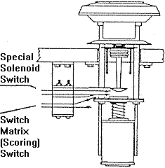
To confuse things even more, the Special solenoids have yet another switch involved.
This is the scoring switch, which is part of the switch matrix (unlike the special solenoid
trigger switch). So each pop bumper and slingshot have a second physical switch mounted on the
playfield device. This switch closes as the coil energizes. This switch matrix switch in turns
tells the CPU to score the device (but does *not* tell the CPU to fire the coil).
So if there's a pop bumper or slingshot that works fine (energizes),
but does not score, often it's because this secondary switch matrix switch is mis-adjusted
or broken.
Slingshots that Barely Fire - the Slingshot Resistor and Cap.
A reader reports having a Flash pinball where the slingshots act strange.
If the pinball hits the slingshot rubber (or it is actuated manually),
it barely fires and there is a small kick. But if both sling rubbers switches are
manually touched together it works fine.
The solutions was to check the 22 mfd 25V cap and 100 ohm resistor in series (black
wire to - side of cap, + side of cap to resistor, resistor to other
side of switch) mounted on the slingshot switches.
These make the slings fire quicker and faster. In this the resistor was broken
on one side, and the capacitor was broken on the other side.
Replaced all the bad parts and it works fine now.
Special Solenoids that work in the Game, but Don't in Diagnostics.
The special solenoids work fine
while playing the game, but don't in the diagnostics. Should anyone
really care? After all, the only use for the CPU control of the special
solenoids is in the diagnostics. But I guess that's up to you to
decide whether it should be
fixed (after all, if the game plays, who cares?), but I'll try and explain
why this could happen.
In diagnostics, the special solenoids are controlled by the CPU via
PIA chips. Sounds simple enough, that's how the other 16 CPU controlled
coils work. But it's not that simple, because unlike the other 16 CPU
controlled coils which are controlled by PIA IC5 on the driver board,
the special solenoids use *four* PIAs for their CPU control!
Here's a logic chart:
Spec
Sol# |
Controlling
PIA |
PIA's Normal
Function |
PF Switch
Connector |
7408
In/Out |
7402
In/Out |
Pre-Drive
2N4401 |
Drive
TIP120/TIP102 |
| 1/17 |
ST1
IC10 pin 19 |
Lamp Matrix
(driver board) |
2J13 pin 5 |
IC6 pin 1/3 |
IC9 pin 2/1 |
Q1 |
Q2 |
| 2/18 |
ST2
IC10 pin 39 |
Lamp Matrix
(driver board) |
2J13 pin 4 |
IC6 pin 10/8 |
IC8 pin 12/13 |
Q3 |
Q4 |
| 3/19 |
ST3
IC11 pin 19 |
Switch Matrix
(driver board) |
2J13 pin 2 |
IC6 pin 13/11 |
IC8 pin 5/4 |
Q5 |
Q6 |
| 4/20 |
ST4
IC11 pin 39 |
Switch Matrix
(driver board) |
2J13 pin 4 |
IC6 pin 4/6 |
IC8 pin 9/10 |
Q7 |
Q8 |
| 5/21 |
ST5
IC5 pin 39 |
Solenoids
(driver board) |
2J13 pin 8 |
IC7 pin 13/11 |
IC9 pin 5/4 |
Q9 |
Q10 |
| 6/22 |
ST
IC18 pin 19 |
Score Displays
(CPU board) |
2J13 pin 9 |
IC7 pin 10/8 |
IC9 pin 12/13 |
Q11 |
Q12 |
Note one of the special solenoid controlling PIAs is on the CPU board,
not the driver board! (Better check that 40 pin interboard connector.)
So if the solenoid IC5 PIA was replaced thinking it would take care
of the special solenoids in diagnostics, chances are 5 out of 6 that the problem
will *not* be fixed! (Usually it's the 7408 chip anyway.)
And the special solenoids are not controlled by the PIA's "normal" ports. Instead
they use CA2 and CB2, which are two specialized ports on the PIA, at pins 19 and 39.
Leon's test chip does test pins 19 and 39 of all the PIAs, but unfortunately
the pulses are usually not as clear as testing the "normal" port at pins 2-17 of the PIAs.
Locked On Special Solenoids- The Trigger Switch, Cap, Resistor.
The bad thing about special solenoids is they are NOT a "one
shot" type device. If a special solenoid playfield trigger switch
gets permanently closed, it's associated coil "locks on", and stays
energized. And it will stay energized until either a fuse blows,
or the coil burns (and in the process burns up the coil's driver board
transistor). It is actually quite common for even a momentarily
locked on special solenoid to burn out its associated driver
transistor, and even the 74xx chips and PIA (this seems
to be a big problem with locked on pop bumpers).
It was strange that Williams choose to *not* make the
special solenoids "one shot", as even Gottlieb did on their non-CPU controlled
"one shot" pop bumper driver boards. Eventually Williams did make
all coils CPU controlled (with System11A), making everything "one shot".
So the moral of this story is to *always* check the special solenoid
trigger switch on the playfield. Also be sure to check the 22mfd 100 volt
capacitor and 100 ohm resistor that are wired in parallel to the switch
(and of course the coil's 1N4004 diode). The resistor can short closed,
essentially causing the playfield switch to be locked on. Same thing
for the capacitor, which can also short internally causing its special
solenoid to lock on. Note the resistor and capacitor can be removed, and
the system will still work (the easiest way to do this is to just
cut either lead of the resistor from its solder lug).
This is a good first step if a special solenoid
is locked on, as it removes another potential problem from the system.
But remember if the playfield switch is stuck on or the resistor/capacitor
is shorted, this could be the whole problem, and what
ultimately caused the "domino affect" of ruining the driver board parts,
the coil, etc. Also remember if the resistor and/or capacitor is cut
for test, they should be replaced or re-attached.
These were added to cause the special solenoid circuit to be
"on" for a brief period of time after the special solenoid switch opens
back up, in order to make the pop bumper "pop" better. It sort of fools
the driver board into thinking the switch is actually staying closed longer
than it really does, making the slingshot or pop bumper kick
a bit harder. Sometimes sluggish pop bumpers or slingshots can be
caused by its associated playfield switch's resitor or capacitor going open.
A pop bumper drawing showing the special
solenoid Trigger switch (not in the switch
matrix), and the scoring switch (which is in
the switch matrix).Pic by Norbert Snicer.
|
Also remember the special solenoid trigger switch is *not* part of
the switch matrix. So the game's switch matrix diagnostics can *not*
be used to test the playfield special solenoid trigger switch.
Testing Coils and Transistors
(Non-Working and Locked On).
There is a whole section about testing driver board transistor in the
Checking Transistors section of this document.
But outside of this, some other tests can also be used.
If unsure about a coil and whether it works, try these simple
tests, with the solenoid fuse F2 installed.
Remember, if a coil is locked on, check if it is a Special
Solenoid (pop bumpers and slingshots). The special solenoids
will "lock on" if their corresponding playfield activiation
switch is stuck on or shorted. So a locked on special solenoid
could be as simple as a permanently closed solenoid playfield switch.
Testing for Overall Solenoid Power.
If the coil does not fire, there may be
no 28 volts from the power supply. For this test,
the solenoid fuse F2 will need to be installed.
Using a DMM set to DC volts, do the following:
- Put the DMM black lead on the power supply ground connector 3J4 pin 1.
- Put the DMM red lead on power supply board connector 3J3 pins6-9.
- Turn the game on.
- There should be 28 to 47 volts DC.
If there is no voltage, check solenoid fuse F2. If this fuse
keeps blowing at power on, the backbox mounted 6BR2
solenoid bridge rectifier has probably shorted. If no voltage
or low voltage, this could also be the solenoid bridge
rectifier.
Testing for Good Coil Ohms.
If a coil has been over-heated (locked-on) previously, the coil
windings can get hot enough to burn their painted enamel
insulation. If this happens, the windings can short, causing
the overall resistance of a coil to be too low (essentially
making the coil a "short"). This can then
stress the driver transistor, eventually blowing it.
To check a coil for this problem, put a DMM on the low ohm
setting, and put each DMM lead on each lug of the coil. It
should read 3 to 150 ohms. If it is any lower than about 2.5 ohms,
the coil probably has an internal short and should be replaced.
Another indication that a coil has been heat stressed is if
its internal nylon sleeve can be removed from the coil. If this
coil sleeve can not be easily removed, chances are good the coil
has gotten hot enough to expand, and the coil should be replaced.
Remember when replacing a coil, the thicker POWER wire(s) go to the
coil lug with the banded side of the diode attached. The thinner
ground wire (which goes to the driver board) goes to the coil lug
with the non-banded side of the diode attached.
Testing for Power at a Coil/Flashlamp.
If the coil does not fire, there may be
no power at that coil or flashlamp.
For this test, solenoid fuse F2 will need to be
installed. Using a DMM set to DC volts, do the following:
- Lift the playfield up on the game.
- Turn the game on and let it go into attract mode.
- Put the DMM black lead on ground (the metal side rail).
- Put the DMM red lead on EITHER coil lug or flashlamp lug.
- Either lug should show 28 volts (for either a coil or flashlamp, as flashlamp
power is the same 28 volt power source).
If only one lug shows voltage, the coil or flashlamp is bad (it has
a broken winding). If
neither lug shows voltage, check "upstream" and see if
the daisy-chained thicker power wire broke off another coil/flashlamp
in the chain.
Testing the Coil/flashlamp.
If a coil or flashlamp is not firing, and
with power at the coil, this test will check if the coil or flashlamp
is capable of firing. For this test, solenoid fuse F2 will need to be
installed.
- Lift the playfield up on the game.
- Turn the game on and let it go into attract mode.
- Using an alligator test lead, attach one end to ground (the game's
metal side rail).
- Momentarily touch the other end of the alligator test lead to
the GROUND coil or flashlamp lug. The ground coil lug is the lug
with the non-banded side of the 1N4004 diode attached
(all coils should have a 1N4004 diode!), and the thinner wire attached.
The ground lug on a flashlamp is the lug that goes to the
resistors (usually the tip of the flashlamp socket).
The coil or flashlamp should fire. If the power lug is accidently
touched with the alligator clip, the solenoid fuse will probably
blow, and the game will probably reboot. If this happens, replace
the fuse and try again (touching the correct coil/flashlamp lug!)
IMPORTANT: While doing this, note the 1N4004 diode on the
coil. Make sure it is in good shape, not cracked or damaged, and
is connected to the coil lugs. More info on this diode is below.
Note there is no diode used on flashlamps.
Testing the Wiring from the Driver Board to the Coil/flashlamp.
For a non-working coil/flashlamp,
now it is verified there is power at the device, and the coil/flashlamp
can actually fire. It's time to see if the wiring from the
coil's non-banded diode lug (or from the flashlamp's resistor
board) goes uninterupted to the driver board.
- Check the schematics or operator's manual and figure out
which TIP120/TIP102 transistor number goes to the coil/flashlamp in question.
Or if schematics are not available, find the non-power wire color at the device.
Then go to the driver board and find that same wire color
at the connectors on the left edge of the driver board. Using a DMM set to continuity, put
one DMM lead on that driver board connector pin and touch the other DMM lead to all the metal tabs
of the driver board left-side TIP120 transistors. This will identify which transistor drives the questionable
device.
- With the game on and in attract mode,
use an alligator test lead, and connect one end to ground in the backbox.
- Using the other end of the alligator test lead, momentarily
touch the metal tab on the coil/flashlamp's transistor.
This should fire the coil/flashlamp in question.
Do this should fire the coil/flashlamp. If it does, the wiring from the driver board
to the coil is OK. If it does not fire, chances are good there is
a bad backbox/cabinet connector (common as the male connector header pin's solder joints
often crack where soldered to the driver board), or the wire is cut somewhere between
the backbox and the coil. If the problem is a non-working flashlamp, make sure to check
the under-playfield resistors for that flashlamp. Because the 12 volt flashlamp is run
at 28 volt solenoid voltage, there are two resistors used as additonal resistive "load"
so the 12 volt flasher doesn't burn out at 28 volts (one resistor is a "keep alive", the
other is used when the lamp is "fired"). If the "fired" resistor goes open, the flash
lamp will never work.
Everything Checks Out So Far, But the Coil/Flashlamp Still Doesn't Work.
Remember, if a coil is locked on, check if it is a Special
Solenoid (pop bumpers and slingshots). The special solenoids
will "lock on" if their corresponding playfield activiation
switch is stuck on or shorted. So a locked on special solenoid
could be as simple as a permanently closed solenoid playfield switch.
At this point, there is a driver board issue. Power is at the device,
and the wiring gets to the driver board, but the coil or flashlamp will
still not fire (or is locked on). This is a good indication
either the driver transistor has failed, or it's driving
7408 chip has failed, or even the driver board solenoid PIA at IC5
has failed.
Check the Driver Board Male Header Pin Solder Joints.
If the driver board is removed, it is really a good idea at this point to
re-solder the header pin connectors on the Driver board (obviously the
driver board needs to be removed for this work.) Heat
the joints with a soldering iron until the solder melts, and add some new solder.
Sometimes it's difficult to get the solder to stick to encompass the head pin "butts".
So an even better method (though more involved) is to remove the old solder
using a desoldering tool, and then resoldering the connector pin with new solder.
This is a good idea because the old solder often does not stick well to the
connector pins "butts".
But attempting to diagnose problems without first doing this is often a waste of time,
because the driver board flexs as it is removed from the 40 pin interboard connector
or as connectors are removed/attached.
This flexing causes cracks in the male header pin solder joints, causing intermittent
or non-working connections.
Testing the Driver Board Transistors.
This should be done for a non-working or locked on coil or flashlamp.
The driver board does not need to be removed for this test, but it does make the job easier.
This procedure is listed in the
Checking Transistors section of this document too.
All transistors are tested using the diode function of a DMM
(Digital Multi Meter).
Important Note: Testing transistors (or chips) using the methods below
does not give 100% proof that a transistor is good or bad.
It's probably about 95% accurate, but it is not 100% accurate
(especially if the transistor is mounted in a circuit board).
I will say this - if a transistor tests as "bad", then it's bad (or the TTL
chip that feeds it is bad).
But if the transistor tests as "good" that does not necessarily mean
the transistor is good.
If the driving TIP120 transistor is bad, be sure to replace it with
a more robust TIP102 transistor. Also make sure to replace the
pre-driver 2N4401 transistor that accompanies the TIP120/TIP102.
At this point, it is best to test the driving 7408/7402
chip. It only takes a moment, and saves a lot of work if this
chip is damaged. Also a bad 7408/7402 can cause a driving transistor
to test as "bad".
Testing the 7408/7402 Chips and Solenoid PIA.
At this point, the TIP120/TIP102 and pre-driver 2N4401 are tested/replaced,
but the coil/flashlamp is still locked on.
Now it's time to test the 7408/7402 driver chips.
No need to test this 7408 chip! The 7408 in the middle is physically
bubbled up and can easily be seen as "bad". It can be counted on that
the 2N4401 pre-driver and TIP120/TIP102 driver transistors are blown too!
Just hope the IC5 solenoid PIA chip survived.
|
These chips can also be tested with a DMM set to the diode function and the
game off. For a 7408, put the red lead on ground (pin 7), and
put the black lead on pins 1,2,3, 4,5,6, 8,9,10, 11,12,13. A reading of of .4
to .6 should be seen for each pin (a reading lower than .2 is a big sign of a
bad chip).
Likewise a 7402 (used for special solenoids)
can be tested in the same manner. With the
game off. For a 7402, put the red lead on ground (pin 7), and
put the black lead on pins 1,2,3, 4,5,6, 8,9,10, 11,12,13. A reading of of .4
to .6 should be seen for each pin (a reading lower than .2 is a big sign of a
bad chip).
Remember though, testing TTL chip mounted in a circuit board
using a DMM's diode test can give false readings.
If the chip is socketed, it's better to use the DMM diode test
with the chip removed from the circuit.
An even better test (with the board powered on) is
to use a logic probe and to compare similar TTL chips.
That is, compare two (or more) similar 7408 or 7402 TTL chips which both control
solenoids (see the schematics).
TIP Transistor & TTL Checks Good, but Coil Locked On - Now What?
In the case of all coil *except* the special solenoids,
the only thing left is the PIA IC5. Luckily in the case of CPU controlled coils this is easy
to test. Have the solenoid power fuse removed. Using a logic probe, the
PIA IC5 outputs can be checked. With the game in attract mode,
all coil outputs from the PIA IC5 should be LOW (except for
the coindoor lockout coil), meaning the coil is NOT energized.
If the PIA outputs are missing or high, the associated coil will be locked on
(remember the coindoor lockout coil will be ON, unless the game is at maximum allowed credits).
The TTL 7408 is a two input, one output AND gate.
This means BOTH input signals must be HIGH for the AND gate to be completed,
making the output AND gate signal HIGH (and energizing the coil). If the game is successfully
booted, the Blanking signal is already high, so one of the AND inputs is high. Now
the 7408 is waiting for the PIA to make the other input AND signal momentarily high
to fire the associated coil.
In the chart below the first listed TTL is the AND gate output.
The next pin number (after the ":") is the AND input from the PIA.
The last TTL pin number is the blanking signal (which should be high in a booted game).
The output TTL pin (first listed TTL pin) should be low with the game in attract mode. If the
TTL input pin coming from the PIA is low, the blanking input TTL pin is high, but
the output TTL pin is high or missing, then the TTL 7408 chip is bad.
Below is a chart of the IC5 PIA and TTL outputs which should
be checked with the logic probe for a "low" signal (game powered on and in attract mode).
The system3-7 CPU controlled solenoid schematic (PIA, AND gate, transistors).
|
| Coil# | Connector | TIP 120 | 2n4401 | TTL (output, in PIA, in Blank) | PIA Output (low) |
| Coil 1 | J11 pin 4 | Q15 | Q14 | IC1 pin 8:10,9 | IC5 pin 2 |
| Coil 2 | J11 pin 5 | Q17 | Q16 | IC1 pin 11:12,13 | IC5 pin 3 |
| Coil 3 | J11 pin 7 | Q17 | Q16 | IC1 pin 6:4,5 | IC5 pin 4 |
| Coil 4 | J11 pin 8 | Q21 | Q20 | IC1 pin 3:1,2 | IC5 pin 5 |
| Coil 5 | J11 pin 9 | Q23 | Q22 | IC2 pin 8:10,9 | IC5 pin 6 |
| Coil 6 | J11 pin 3 | Q25 | Q24 | IC2 pin 11:12,13 | IC5 pin 7 |
| Coil 7 | J11 pin 2 | Q27 | Q26 | IC2 pin 6:4,5 | IC5 pin 8 |
| Coil 8 | J11 pin 1 | Q29 | Q28 | IC2 pin 3:1,2 | IC5 pin 9 |
| Coil 9 | J9 pin 9 | Q31 | Q30 | IC3 pin 8:10,9 | IC5 pin 10 |
| Coil 10 | J9 pin 7 | Q33 | Q32 | IC3 pin 11:12,13 | IC5 pin 11 |
| Coil 11 | J9 pin 1 | Q35 | Q34 | IC3 pin 6:4,5 | IC5 pin 12 |
| Coil 12 | J9 pin 2 | Q37 | Q36 | IC3 pin 3:1,2 | IC5 pin 13 |
| Coil 13 | J9 pin 3 | Q39 | Q38 | IC4 pin 8:10,9 | IC5 pin 14 |
| Coil 14 | J9 pin 4 | Q41 | Q40 | IC4 pin 11:12,13 | IC5 pin 15 |
| Coil 15 | J9 pin 5 | Q43 | Q42 | IC4 pin 6:4,5 | IC5 pin 16 |
| Lockout | J9 pin 6 | Q45 | Q44 | IC4 pin 3:1,2 | IC5 pin 17* |
*Unless game is at maximum allowed credits, the coin door lockout
PIA output will be high.
Leon Test EPROM could also be used for this test, but frankly I find that not necessary.
It's just easier to be running the game code in attract mode and testing the outputs
with a logic probe. But the Leon test chip procedure
is fully described in the Dead/CPU driver board sub-section,
CPU board is working, Install the Driver board.
This shows how to test the PIA using a "tester LED" and
Leon's test chip.
FlashLamp Problems.
Flashlamps are controlled as solenoids, and are wired in series
(if there is more than one flashlamp fired by a single driving transistor).
The flashlamps are "doubled up" and wired in series so that
the 28 volt solenoid voltage can be used on the 14 volt flasher bulbs
(two times 14 equals 28 volts). But the problem with this is
if one flashlamp burns out, the other flashlamp will not work!
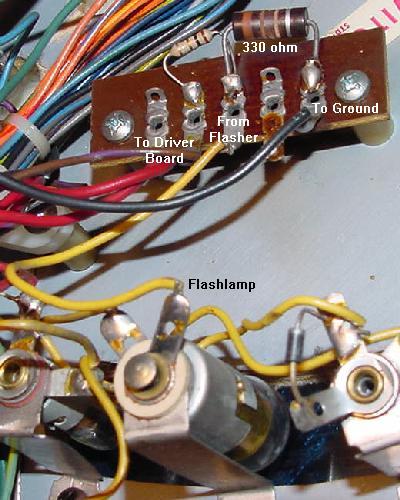
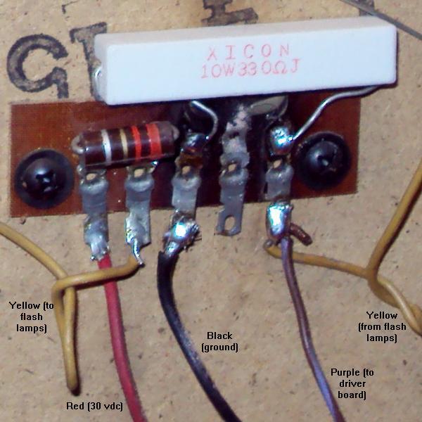
The resistor board for the flashlamp. The large 330 ohm 2 watt
resistor is permanently connected between the flash lamp & ground.
This keeps the flashlamp's filiment warm while the game is on,
letting 12 volts to the bulb all the time through the 330 ohm
resistor (this increase bulb life by keeping the filament warm).
When the flashlamp is fired by the game, ground is then completed
through the small 1 ohm (or 5 ohm) resistor, and the flashlamp
turns on brightly. Electricity takes the path of least resistance,
going through the 1 ohm resistor instead of the 330 ohm resistor.
The 330 ohm resistor is often burnt or desolders itself from its
board because power is going through it all the time (except when
the flash bulb actually flashes). This game is Firepower.
Williams used this bulb warming approach through System 11, but
abandoned it with WPC.
|
Another view of the flash lamp board on Firepower.
|
Flashers also have two resistors connected to them, one large 330 ohm
2watt, and one small 1 ohm (or 5 ohm) 1/2 watt.
When the flash lamps are not lit, the path to ground for the flash lamps
is completed via the large 330 ohm and smaller 1 ohm resistors together.
This keeps the bulb filiments warm
(and less likely to burn out and also more likely to give a BRIGHT flash).
On some flashlamps, they can look like they are glowing
slightly when not in use.
A cold flashlamp would take too long to get bright, so the flash would
have less impact, so that's why Williams did this.
When the driver board transistor is turned on,
the ground path is switched directly through the driver board, and the 330 ohm
resistor is essentially eliminated from the circuit
(because current will take the path of least resistance).
Note the 1 ohm resistor is still utilized.
Flash lamp board on Laserball. Note the wiring is a big different,
the the circuit is the same as used on Flash/Firepower (except the small
resistor is 2.2 ohms instead of 1 ohm.)
|
Close up of flash lamp board on Laserball, after the 330 ohm "warm up bulb"
resistor was changed to a 10 watt version (recommended.)
|
If a flash lamp is dull or sluggish, check the 330 ohm heater resistor.
These resistors do burn and break (or get cold solder joints, or
just fall off their solder terminal!), not allowing the flash lamp to "pre-heat".
If this happens, it won't pre-heat
the flash lamp, and the flasher may not flash!
Also if flash lamps burn out often, the 330 ohm resistor could be bad.
Be sure to check the 1 ohm (or 5 ohm)
resistor too, as these can go open, and neither flashlamp will work.
The wiring for Flashlamps and Coils. Note the two flashlamps in series, and the
330 ohm resistor path to ground, that keeps the flashlamps "warm" (and dim).
Then when the driver board ground path is used, the flashlamps turn on brightly,
as the 330 ohm resistor ground path is negated.
|
The Coil Diodes and Why they are Important.
After testing or replacing a driver board transistor, it is
important to examine the coil in the game. If any
coil (especially the one that was just locked on)
has a bad diode, this can almost instantly
kill its associated driver transistor! The coil diode
prevents a coil's collapsing voltage from "backwashing" to the
driver board, damaging the driver transistor.
Since you spent the time to test/replace the bad driver
board transistors, it only makes sense to also check for
bad coil diodes. Since these 1N4004 diodes are mounted
right to the coils under the playfield, vibration can crack
or damage them.
The best way to test a coil diode is to just grab the diode by
its body with the forefinger and thumb, and gently give
it a pull. If the diode has a cracked body or broken
lead, it should be pretty easy to see.
The 1N4004 coil diode mounted on a Firepower slingshot,
showing the proper orientation of the diode and power wires.
|
Coil diodes (1N4004) can be tested with a
DMM set to the diode function:
- Turn the game off.
- Unsolder or cut one end of the diode from the coil.
- Use a DMM set to the diode function.
- Put the blank DMM lead on the banded side of the diode.
- Put the red DMM lead on the NON-banded side of the diode.
- .4 to .6 volts should be seen.
- Reverse the DMM leads, and a null reading should be seen.
- If these values are not seen, replace the diode with a
new 1N4004 diode.
If a new diode is needed, remember to install it with the
diode's band on the power lug of the coil! It usually pretty easy
to tell which is the power lug of a coil. The power wire, which daisy
chains from coil to coil, is usually the thicker wire on a coil
lug. The banded lead of the 1N4004 diode should be connected to the
coil lug with this thicker daisy chained power wire attached.
The non-banded end of the diode attaches
to the coil lug with the thinner wire, which leads to the driver board transistor,
and ultimately ground.
3f. When Things Don't Work: Lamp Problems (the Lamp Matrix)
Introduction.
Remember, there are GI (General Illumination) lamps, and CPU controlled
(lamp matrix) lamps. The GI lamps come on as soon as the game power is
turned on. And these lamps generally do not turn off (except on Blackout, Scorpion
and System7 games, where there is a GI lamp relay to toggle all the GI
lamps on and off). The CPU controlled lamp matrix, when the game is
in attract mode (game over), will turn playfield and backbox lamps
on and off. The CPU controlled lamps also work during game play,
to light certain features to help the player.
The CPU controlled lamps (the "lamp matrix") uses +18 volts DC to drive the CPU
controlled lamps. If you're asking, "how do they use 18 volts to light
6.3 volt bulbs?", you would be asking a good question. While the lamp power supply
outputs a constant 18 volts DC from the backbox mounted bridge rectifier and
filter capacitor, the driver board "pulses" the 18 volts to the lamps.
This turns the lamps on and off very quickly, so that they never get to
full brightness, and are only on about 1/3 of the time (which roughly works
out to about 6 volts).
Turning the bulbs off and on like this increases light
bulb life, which is a nice feature since most operators don't change burnt out
lamps!
Important note about the lamp matrix: because the game is constantly pulsing
the lamp matrix to bring the 18 volts down to about 6 volts, these games
should NEVER be left on when they are "locked up". Because if they are locked
up, the lamp matrix is not strobing, which can burn out the playfield lamps
and COOK the driver board. The heat can get so bad on a driver board, that
it will start to desolder parts!
The lamp matrix power supply has only three components: a backbox mounted
35 amp 400 volt bridge rectifier, and very large 30,000 mfd filter capacitor,
and a fuse on the power supply board (F3).
There are some consistent lamp numbers from game to game.
For example, all system3 to system6 games consistently
used lamp column8 for the same functions (player up, tilt,
game over, etc.) With system7, Williams basically moved
column8 to column1. And with the last three system7
games (FirepowerII, Laser Cue, Starlight), this
changed yet again (still using column1, but the row order
changed). Below are the consistent lamps used in
system3-system6 and system7 (except Joust, FirepowerII, Laser Cue, Starlight)
lamp matrix:
Column/
Row |
Col. 1
Yel-Brn
2J5-8 |
Col. 2
Yel-Red
2J5-9 |
Col. 3
Yel-Orn
2J5-6 |
Col. 4
Yel-Blk
2J5-7 |
Col. 5
Yel-Grn
2J5-3 |
Col. 6
Yel-Blu
2J5-5 |
Col. 7
Yel-Vio
2J5-1 |
Col. 8
Yel-Gry
2J5-2 |
Row 1
Red-Brn
2J7-1 |
#1
Extra Ball
(sys7*) |
#9 |
#17 |
#25 |
#33 |
#41 |
#49 |
#57
Player1 Up
(sys3-6) |
Row 2
Red-Blk
2J7-2 |
#2
Ball in Play
(sys7*) |
#10 |
#18 |
#26 |
#34 |
#42 |
#50 |
#58
Player2 Up
(sys3-6) |
Row 3
Red-Orn
2J7-3 |
#3
Tilt
(sys7*) |
#11 |
#19 |
#27 |
#35 |
#43 |
#51 |
#59
Player3 Up
(sys3-6) |
Row 4
Red-Yel
2J7-4 |
#4
Game Over
(sys7*) |
#12 |
#20 |
#28 |
#36 |
#44 |
#52 |
#60
Player4 Up
(sys3-6) |
Row 5
Red-Grn
2J7-5 |
#5
Match
(sys7*) |
#13 |
#21 |
#29 |
#37 |
#45 |
#53 |
#61
Tilt
(sys3-6) |
Row 6
Red-Blu
2J7-6 |
#6
Hi-Score
(sys7*) |
#14 |
#22 |
#30 |
#38 |
#46 |
#54 |
#62
Game Over
(sys3-6) |
Row 7
Red-Vio
2J7-9 |
#7 |
#15 |
#23 |
#31 |
#39 |
#47 |
#55 |
#63
Shoot Again
(sys3-6) |
Row 8
Red-Gry
2J7-8 |
#8 |
#16 |
#24 |
#32 |
#40 |
#48 |
#56 |
#64
Hi-Score
(sys3-6) |
* Except Joust, Firepower II, Laser Cue, Starlight.
All the CPU Controlled Lamps Do Not Work.
Most CPU controlled lamp problems are driver board associated.
However if all the CPU controlled lamps are off and everything else is working,
check power supply fuse F3 and the voltage coming out of the power supply.
Using a DMM, measure the voltage from power supply connector 3J4 pin 5
to 3J4 pin 1 (ground). There should be 18 volts DC.
If there is no voltage (and fuse F3 is good), then chances are good that
the backbox mounted lamp matrix bridge rectifier 6BR1 has failed.
A Row or Column of Lamps does not Work, or is Locked On.
This problem is usually driver board related.
If a row or column is not working at all,
the first thing to try is to resolder the
.156" Molex male header pins on the driver board. The
solder joints on these often crack (from insertion/removal
of the connectors). This would include these driver board connectors:
- 2J4 (lamp matrix power)
- 2J5 (lamp matrix columns)
- 2J6 (lamp matrix ground)
- 2J7 (lamp matrix rows)
The next thing to suspect are the column/row transistors.
These can be tested with a DMM set to the diode function
and the game turned off. Keep in mind that column transistors die more
than row transistors.
Important Note: Testing transistors (or chips) using the methods below
does not give 100% proof that the component is good or bad!
It's probably about 95% accurate, but it is not 100% accurate
(especially with the transistor soldered into a board).
Lamp Columns (drive/strobe): test the TIP42, game off.
Q63, Q65, Q67, Q69, Q71, Q73, Q75, Q77.
Using a DMM set to the Diode function:
- Orient the transistor's writing facing towards you.
- Black DMM lead on *left* leg (base) of transistor.
- Red DMM on center leg (or metal tab), .4 to .6 volts seen.
- Red DMM on left leg, .4 to .6 volts seen.
Lamp Rows: test the 2N6122 (or TIP41), game off.
Q47, Q49, Q51, Q53, Q55, Q57, Q59, Q61.
Using a DMM set to the Diode function:
- Orient the transistor's writing facing towards you.
- Read DMM lead on the *left* leg (base) of transistor.
- Red DMM lead on the center (collector) leg (or metal tab), .4 to .6 volts seen.
- Red DMM lead on the right (emitter) leg, .4 to .6 volts seen.
Driver board or Playfield Problem?
Say you have a game where, in attract mode,
colums 4 through 8 are very bright and the top four resistors on
lower right side of driver board are getting warm.
If you start a game and some lamp matrix lights stay locked-on, and some will
still strobe like in attract mode. Is the problem on the playfield
(shorted socket diode, mis-wired, or shorted lamp socket), or on the driver board?
To determine where the problem is, with the game on,
remove the lamp column connector 2J5 and lamp row connector 2J7
from the driver board (the row and column connectors).
Leave the lamp power 2J4 and lamp ground
2J6 connectors in place. Jump any one of the four
overly-bright columns pins on 2J5 to any lamp row connector pin on 2J7
using two alligator clip leads and a light bulb (#47 or #44). If this single
bulb is still overly bright, then the problem is on the driver
board. If the lamp lights normally, there are two
lamp column wires shorted together somewhere on the
playfield.
Testing a Lamp Row/Colums with the Game On.
Another way to test the lamp rows (and indirectly the
columns) is to do this:
- Turn the game on.
- Press the manual-down/auto-up coin door button to manual-down.
- Press the advance coin door button once. The score displays
should go blank.
- Press the advance coin door button again. The score displays
should all show zeros.
- Using a alligator test lead, attach one end to ground
(the grounding braid in the bottom of the backbox
or pin 40 of the interboard connector).
- Touch the other end of the alligator test lead to any
one of the driver board transistors Q47, Q49, Q51,
Q53, Q55, Q57, Q59 or Q61 (these are all in a vertical row
in about the center of the driver board).
- All the corresponding playfield lamp matrix row lights should
all turn on (eight lamps in all). If less than eight light,
refer to the operator's guide and see which lamps in the particular
row are not turning on, and make a note of it.
- Move the alligator test lead to the next lamp matrix row
transistor to test the next eight row lamps.
If several lamps did not turn on, check the operator's
manual and see if all eight lamps are in the same column or row.
Note this does not test the row or column transistors themselves.
It just tests everything from the driver board to the playfield.
Also do NOT repeat this test for the *column* transistors!
Doing that will blow the lamp matrix fuse.
Pre-Drivers: test the 2N6427 (or MPSA14), game off.
Columns: Q61, Q64, Q66, Q68, Q70, Q72, Q74, Q76.
Rows: Q46, Q48, Q50, Q52, Q54, Q56, Q58, Q60.
These pre-drive both the above TIP42 and 2N6122 transistors.
Using a DMM set to the Diode function:
- Red DMM lead on middle leg.
- Black DMM lead on right leg, 1.0 to 1.3 volts seen.
- Black DMM lead on left leg, .6 to .8 volts seen.
Lamp Row(s) Stuck On - Troublesome 7406 Chip IC19.
This is a very common problem with system3 to system7 games,
where one or multiple lamp rows are stuck on. In my experience,
it is usually not the row transistor(s) that are the problem.
It is usually the 7406 chip at IC19 on the driver board. This chip
handles the logic for six of the eight lamp rows (the other two
rows are handled by IC12).
A lamp matrix lamp. Note the wiring of the row and
column wires, and the orientation of the diode.
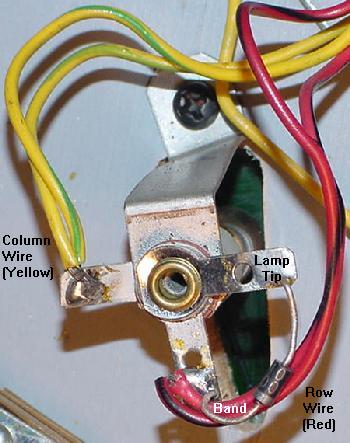
|
One Lamp Does not Work.
Assuming the bulb is not burnt out, here are some things to check:
- Check the lamp socket. Yes sockets do go bad. With time,
the fiber insulators shrink, allowing air to corrode the parts,
and the socket does not make contact to the solder lugs.
- Also check for a shorted lamp socket. This can happen easily
when doing other repairs. Often a shorted lamp socket will usually
short out other lamps in the same row/column too.
- A broken or open lamp diode. There is a 1N4001 diode mounted
on each lamp socket. If this diode is broken, missing or has gone
open, the lamp will not work! There are rare cases that when a
lamp burns out, it also burns out its diode too.
- The lamp row and column wires are "daisy chained" from socket
to socket. Has the daisy chain broken "up stream?" This will cause
all the lamps "down stream" to not work.
- Check for a shorted diode. This does not happen as often as
open diodes, but its worth checking. Shorted diodes can happen
if lamp matrix light bulbs are changed with the game on, and
the lamp drive is accidentally grounded through the diode.
A shorted diode usually causes one or more lamps to be ON at the same
time.
Using a Logic Probe to Test the Columns/Rows.
Turn the game on and put it in the lamp matrix test, with the lamp
matrix fuse F3 installed. This will
turn all the computer controlled lamps on and off about every second.
Now remove the driver board connectors 2J5 (lamp columns)
and 2J7 (lamp rows). This will take the
playfield out of the picture (where there could be a row/column
short).
Put the logic probe on each pin
on 2J5 (columns). The pins should be constantly pulsing. If any pin
is not pulsing, its probably a bad TIP42 transistor (Q63,Q65,Q67,Q69,
Q71,Q73,Q75,Q77), or the pre-driver 2N6427 (Q61,Q64,Q66,Q68,
Q70,Q72,Q74,Q76).
To test the lamp row is similar. Again with the game in the lamp matrix
test, use the logic probe on each pin of 2J7 (lamp rows).
Each pin will pulse in time, turning on and off about every second (just like the playfield
lamps flashed before the lamp connectors were removed).
If any pin is not pulsing, its
probably a bad 2N6122 transistor at Q47,Q49,Q51,Q53, Q55,Q57,Q59,Q61.
Also it could be the pre-driver 2N6427 transistors at
Q46,Q48,Q50,Q52, Q54,Q56,Q58,Q60.
The 7408 Lamp Column & 7406 Lamp Row Chips.
If a row or column is still locked on or not working, next look
at the 7408 chips that drive the lamp columns. These are at
IC13 and IC14. Also there 7406 lamp row chips at IC12 and IC19.
The IC12/IC19 lamp row 7406 buffer chips actually fail quite often, compared to the
lamp column chips.
These chips can be tested with a DMM set to the
diode function and the game off. For the 7408 at IC13/IC14,
put the red lead on ground (pin 7), and put the
black lead on pins 1,2,3, 4,5,6, 8,9,10, 11,12,13.
A reading of of .4 to .6 should be seen for each pin (a reading
lower than .2 is a big sign of a bad chip).
Likewise the 7406 at IC12/IC19 can be tested in the
same manner. With the game off, put the DMM's red lead
on ground (pin 7) and put the black lead on pins 1,2, 5,6, 8,9, 10,11, 12,13.
Again a reading of of .5 to .7 should be seen for each pin (a reading
lower than .2 is a big sign of a bad chip).
Remember though, testing TTL chip mounted in a circuit board
using a DMM's diode test can give false readings.
If the chip is socketed, it's better to use the DMM diode test
with the chip removed from the circuit.
An even better test (with the board powered on) is
to use a logic probe and to compare similar TTL chips.
That is, compare two (or more) similar 7408 or 7406 TTL chips which both control
lamps (see the schematics).
The Lamp Matrix PIA at IC10.
Though rare, there is a chance the lamp matrix 6821 PIA on the
driver board at IC10 has failed. I would really make sure though
that all the row/column transistors and 7406/7408 chips are not bad first
(they are much more likely to fail).
Really the only way to test
this chip is to use Leon's test EPROM
chip and a "tester LED".
This is best done with the
CPU and driver board removed from the game, and powered up
on the work bench with a computer power supply (as described in the
Fixing a Dead CPU/Driver board section).
If this is done in a game, remove power supply fuses F2 and F3,
the driver board connectors at 2J4, 2J5 and 2J7.
Lamp Matrix Strobe (Column) Test (Connector 2J5).
To test the lamp matrix columns, power has to be applied to any pin of
driver board connector 2J4.
Normally this is +18 volts, but for our test, +5 volts will work
fine. Using an alligator test clip, connect +5 volts
(TP9 on system6/7 CPU board, or interconnector pin 1 on the far right)
to any pin of driver board connector 2J4.
In addition, the connectors at both 2J5 and 2J7 need to be
attached from the game. If testing "on the bench", an alternative
method can be used (see below).
Now connect the tester LED's non-resistor lead to +5 volts.
Using the resistor lead of the tester LED,
touch each pin of driver board connector 2J5.
The tester LED should alternate on and off, in unison with the
blinking LEDs on the CPU board.
If the CPU/driver board combo is on a bench with no access to
the playfield connectors 2J5 and 2J7, another method must be used.
With the tester LED's non-resistor end connected to +5 volts,
touch the tester LED's resistor end to the left most leg of
each transistor Q62, Q64, Q66, Q68, Q70, Q72, Q74 and Q76 (the
small transistors along the right edge of the driver board).
The tester LED should alternate on and off, in unison with the
blinking LEDs on the CPU board (the tester LED will not work
directly on connector 2J5 without the playfield connectors 2J5/2J7).
If the alternating signal is missing,
yet all the IC10 lamp PIA signals are present,
check the inputs of IC13 or IC14 (7408) on the driver board (pins
1,2,4,5,9,10,12,13 of IC13 and IC14). If there is no input signal,
there is a bad TIP42 (Q63,Q65,Q67,Q69, Q71,Q73,Q75,Q77)
driver transistor or 2N6472 (Q62,64,66,68, 70,72,74,76) pre-driver transistor
feeding the chip. Then check the output signals
of IC13 and IC14 (pins 3,6,8,11). If
the input signal is turning on and off, but there is no output signal,
the chip is bad. Note the output signal from the chip may be very short.
Lamp Matrix Row Test (Connector 2J7).
This test also requires +5 volts power to any pin of driver board connector 2J4.
Normally this is +18 volts, but for our test, +5 volts will work
fine. Using an alligator test clip, connect +5 volts
(TP9 on system6/7 CPU board or interconnector pin 1 on the far right)
to any pin of driver board connector 2J4.
In addition, this test also requires a ground connection
to any pin of driver board connector 2J6
(if the boards are installed in the
game, just have the game connector attached at 2J6).
Once power and ground are applied to the lamp matrix,
now connect the tester LED's non-resistor lead to +5 volts.
Using the resistor lead of the tester LED,
probe on each pin of driver board connector 2J7.
The tester LED should alternate on and off, in unison with the
blinking LEDs on the CPU board.
If the alternating signal is missing
on any connector 2J7 pin, yet all the IC10 PIA signals are present,
check the outputs of IC19 or IC12 (7406) on the driver board (pins
2,4,6,8,10,12 of IC19 and pins 2,4 of IC12). If there is no output signal,
the chip is bad. If the output is good, there is a
bad 2N5060, 2N6427 or 2N6122 transistor.
Should the Big Lamp Matrix Capacitor be Replaced?
They are hard to find and expensive, so
unless its leaking and/or bulging, I would not suggest replacing the
large backbox mounted lamp matrix filter capacitor.
If fuse F3 is good, and the lamp matrix bridge rectifier is good, it's
really the only component left (other than the transformer itself).
So check the AC voltage coming out of the transformer before replacing
this large capacitor.
Fixing the Eight Large Burnt Lamp Matrix Resistors.
To fix the large burnt lamp matrix resistors,
a couple things can be done. First, replace these eight driver
board R149-R156 resistors with 27 ohm 5 watt sand or ceramic wire wound resistors.
Also make sure to install the new resistors about 1/4" off the circuit board to
allow better air flow around them. Another good idea is to use #47 light bulbs
for the feature lamps, as this will decrease feature lamp power consumption by about 40%!
Yet another option to fix the burnt resistors is an idea documented by C.Eddy.
He replaces the eight TIP42 PNP lamp matrix transistors (Q63, Q65, Q67, Q69, Q71, Q73, Q75, Q77)
with IRF9z34n mosfets (or IRL9530). The MOS-FETs are installed oriented just like the TIP42 transistors.
And the mosfets only need a tiny amount of current to drive them (compared to the 2 watts of
power draw by the TIP42 transistor),
hence the large power resistors at R149-R156 never get hot. Because of this there is no need
to replace the large resistors (the old burnt ones can be left installed, unless they are open).
Heck if the TIP42s are replaced with IRF9z34n (or IRL9530) mosfets the power resistors R149-156 can even be
replaced with jumper wires or zero ohm resistors, but it's probably a better idea to just leave
the original 27 ohm resistors in place.
Another option is to replace the TIP31 (2n6122) NPN transistors with IRL530 mosfets.
This again is a similar situation. The TIP31's don't overheat as much as the TIP42's,
so it's not as pertinent a design change. The power resistor again should just be left installed.
The TIP31's can draw as much as 3 watts of power, so the IRL530 replacements save a fair
amount of energy.
The blue box shows where the IRF9z34n Mosfets install to replace the TIP42 transistors.
The red box shows where the IRL530 Mosfets replace the TIP31/2n6122 transistors.
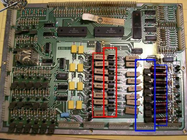
3g. When Things Don't Work: Switch Problems (the Switch Matrix)
System3 to System7 games has a switch matrix of eight columns and eight rows
that allows up to 64 individual switches per game.
The CPU/Driver board will "strobe" (send a voltage) a switch column,
and then read the switch rows (inputs) to see which switches are closed and returning
current. All pinball manufacturers uses this style of switch matrix
(even Gottlieb!)
Special Solenoid Switches Not in the Switch Matrix.
Note there are some switches that are not in the switch matrix!
This includes the coin door Auto-up/Manual and Advance switches, and the
six switches for the special solenoids. The six special solenoid switches
include the pop bumpers and slingshot activation trigger switches.
These non-switch matrix switch activates the device (like the spoon
switch on the pop bumper, or the slingshot switch the ball hits on
the playfield). But these
devices also have a second switch that *is* in the switch matrix,
and handles the scoring for these devices. The second switch is
closed as the device energizes, hence telling the CPU to score
points for that device.
Using the Built-in Switch Diagnostics and an Alligator Jumper.
At this point I assume the game is basically working
(except for some/all of the switches). Because if the game is
at least semi-working, the internal game diagnostics can be
used to help isolate problems and identify switch problems.
The purpose of this test is to find if the switch problem is
on the playfield or on the driver board (you must know this
to fix the problem).
To access the switch diagnostics:
- Turn the game on and allow it to go into attract mode.
- Press the coin door Auto-up/Manual switch into the manual position.
- Press the coin door Advance button. On system3 to system6,
the score displays should go blank. On system7, all the score displays
will light up with "0000000".
- Press the coin door Auto-up/Manual switch into the auto-up position.
- System3 to System6 only: Press the coin door Advance button.
- The game should now go into the first test, which is
the score display cycle test. All the score displays (including the credit/ball-in-play)
should repeat "000000" to "999999".
- System 7 only: Quickly press the Advance button again to pass over the
score display test. This will go
to test 00, as indicated in the credit score display, which is
the sound test. Each sound number will be displayed in the ball-in-play
window, and played on the sound card.
- Quickly press the Advance button again to pass over the previous test.
This will go to test 01,
as indicated in the credit score display, which
is the lamp matrix test (all the CPU controlled lamps
will cycle on and off at once).
- Quickly press the Advance button again to pass over the lamp test.
This will go to test 02,
as indicated in the credit score display, which
is the solenoid test, and each solenoid from 01 to 22 (as
indicated in the ball-in-play display) will be exercised.
- Quickly press the Advance button again to pass over the solenoid test.
This will go to test 03,
as indicated in the credit score display, which
is the switch matrix test.
On system3 to system6,
the ball-in-play display will show the last read (closed)
switch number. On system7 only, if there are multiple switches closed, the switch
numbers will alternate in the ball-in-play display.
Any playfield switch can be activiated, and its
switch number should show in the ball-in-play display. The game manual
or game instruction booklet has a list of the switch numbers,
and their associated switch numbers. Also note the flipper relay
is activated in the switch test so the flippers will work,
and the special solenoids will also work in the switch test.
Now disconnect the driver board connectors at
2J2 (columns) and 2J3 (rows) at the upper right. These are the connectors for the
playfield switches. Both connectors are at the upper right of the driver board.
Use an aligator test wire and run it from
2J2 pin 1 (col1) and touch the other end of the wire to 2J3 pin 1 (row1). Should see
one switch number come on the score display.
Then tough the next pin on 2J3. After eight pins on 2J3 are tested
(all should report one switch closure on the score display),
move the jumper to the next pin on 2J2 (col2) and repeat. Do this for all pin
combination (it only takes a couple minutes). If a single pin jump gives more than one
switch closure or no switch closure, there is a driver board board.
If all a single switch reports for all pins then the problem is on the playfield.
If there is switch column problem at 2J2, it's usually IC17,IC18 (7406).
If a switch row (inputs) at 2J3 is a problem, check
chips IC15,IC16 (4049). Personally I find the column chips
to be more of a problem than the row chips. Beyond that,
the driver board PIA IC11 (6821) could also be the problem
since it interprets all row and column data.
The PIA can be checked with Leon's test chip.
- 2J2 pins 1-3,5 (Columns 5-8 switch drives): IC18 (7406)
- 2J2 pins 9-6 (Columns 1-4 switch drives): IC17 (7406)
- 2J3 pins 1,3-5 (Rows 5-8 switch inputs): IC16 (4049)
- 2J3 pins 9-6 (Rows 1-4 switch inputs): IC15 (4049)
Remember that on connectors 2J2 and 2J3 that pin1 is column or row8,
and pin 9 is column or row1 (kind of opposite what you might expect).
Also check the manual for the maximum switch number used in the game.
Some games don't use any switch numbers past a certain number, and
these upper number switches may not report in the switch test.
Switch Numbers.
There are some consistent switch numbers from game to game
in the system3 to system7 game series. This includes all
the switches in column one (switch numbers 1 to 8),
which included the coin switches, start button, high
score reset, slam and tilts.
Column/
Row |
Col. 1
Grn-Brn
2J2-9 |
Col. 2
Grn-Red
2J2-8 |
Col. 3
Grn-Orn
2J2-7 |
Col. 4
Grn-Yel
2J2-6 |
Col. 5
Grn-Blk
2J2-5 |
Col. 6
Grn-Blu
2J2-3 |
Col. 7
Grn-Vio
2J2-2 |
Col. 8
Grn-Gry
2J2-1 |
Row 1
Wht-Brn
2J3-9 |
Sw# 1
Plumb Bob
Tilt |
Sw# 9 |
Sw# 17 |
Sw# 25 |
Sw# 33 |
Sw# 41 |
Sw# 49 |
Sw# 57 |
Row 2
Wht-Red
2J3-8 |
Sw# 2
Ball Roll
Tilt |
Sw# 10 |
Sw# 18 |
Sw# 26 |
Sw# 34 |
Sw# 42 |
Sw# 50 |
Sw# 58 |
Row 3
Wht-Orn
2J3-7 |
Sw# 3
Start
Button |
Sw# 11 |
Sw# 19 |
Sw# 27 |
Sw# 35 |
Sw# 43 |
Sw# 51 |
Sw# 59 |
Row 4
Wht-Yel
2J3-6 |
Sw# 4
Right Coin
Switch |
Sw# 12 |
Sw# 20 |
Sw# 28 |
Sw# 36 |
Sw# 44 |
Sw# 52 |
Sw# 60 |
Row 5
Wht-Grn
2J3-5 |
Sw# 5
Center Coin
Switch |
Sw# 13 |
Sw# 21 |
Sw# 29 |
Sw# 37 |
Sw# 45 |
Sw# 53 |
Sw# 61 |
Row 6
Wht-Blu
2J3-4 |
Sw# 6
Left Coin
Switch |
Sw# 14 |
Sw# 22 |
Sw# 30 |
Sw# 38 |
Sw# 46 |
Sw# 54 |
Sw# 62 |
Row 7
Wht-Vio
2J3-3 |
Sw# 7
Slam
Tilt |
Sw# 15 |
Sw# 23 |
Sw# 31 |
Sw# 39 |
Sw# 47 |
Sw# 55 |
Sw# 63 |
Row 8
Wht-Gry
2J3-1 |
Sw# 8
Hi-Score
Reset |
Sw# 16 |
Sw# 24 |
Sw# 32 |
Sw# 40 |
Sw# 48 |
Sw# 56 |
Sw# 64 |
Look for Coin Door Switch Problems.
Again before ripping up the driver board, check the coin door switches.
As you can see from the chart above, switch rows 4,5,6,7 use coin door
switches. If these switch(es) are stuck closed, this can cause all sorts
of switch matrix problems. So do a quick visual check of the coin door
switches to make sure they are "open". Also check the row 1,2 tilt
switches (plumb-bob and ball roll tilts).
Cracked Male Header Pins on the Driver board.
The two upper right driver board switch connectors J2 and J3
can have cracked male header pin solder joints.
This can cause an entire switch matrix row or column to not work.
Before tearing up any driver board parts, it's good to test
for this problem. With the game in diagnostic switch test,
hold down one non-working playfield switches (obviously the
switch test won't show this switch on the score displays.) Then at
the same time put some pressure on the two row/column
driver board connectors J2,J3. Does the switch start working?
If so then then the driver board has an issue with either
that switch connector, or the male header pin's solder joint
is cracked at the driver board. I see this problem a lot on these
games.
Testing the Row/Column Chips with a DMM.
The row chips (4049 at IC15/IC16) and column chips (7406 at IC17/IC18)
can be easily checked with the power off using a DMM set to diode test.
With the power off, remove the two switch connectors J2 and J3
from the driver board (two upper right connectors.)
Put the red DMM lead on ground, probe each of the switch matrix
chip legs with black DMM lead. The chip legs should show .4 to .6
volts on the meter (except for 4049 pins 7,14
and 7406 pins 1,7,12,14).
Usually when one of these chips goes bad, the
meter will show a near short like .2 or less, or
some value higher than .8 volts. It's generally
pretty obvious, and it happens a lot on these driver boards.
Particularly problematic are the two 7406 colum driver chips at IC17/IC18.
Beyond the row and column chips is the switch matrix PIA at IC11 (6821). That too
can be tested with a meter set to diode function. But a better method
is to use Leon's test chip with an LED probe.
System3 to System6 Driver Board Switch Matrix Jumper Upgrade.
It's a good idea to upgrade System3
to System6 driver boards to be upward and downward compatible from System7
to System3. To do this, replace the 1000 ohm (system3) or 330 ohm (system 4-6)
resistors R204-R211 in the upper right hand corner with zero ohm jumpers.
System7 driver boards already have this modification done.
The decrease in these switch matrix resistor ohms was done to increase
the current drive through the switch matrix.
For example, if a switch or connector was dirty and had slight
resistance, the switch could still be sensed by the CPU/Driver board.
There is a rumor that using a jumpered system7 style driver board in a System6 or earlier
game may result in random switch closures during game play. This does not
seem to be the case (but keep it in mind if having random switch closure problems).
One thing for sure though is using
a non-jumperd System3 to system6 driver board game in a System7 game
will definately result in switch closures being missed.
An incorrectly assembled factory switch on a Firepower.
The short (top) leaf's gold plated contact is *not* facing
the long leaf's gold contact (it is reversed!) So instead
of nice smooth gold-on-gold contacts, there is one nice
gold contact and a gnarley rivet making contact.
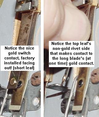
|
Strange Switch Behavior.
A user reported a problem on his Firepower when the ball was locked
in the left kickout hole switch #13,
no other switches in that column #2 with a higher switch row number
would work (#14,15,16). If the ball was *not* locked, all the switches in that column
worked fine. All the switch diodes were checked for shorts or breaks.
Running a switch test as described above with an alligator clip and diode across
the driver board connectors showed no problems either.
The problem turned out to be one of the two 4049 switch row chips at IC16,
for switch inputs rows 5-8. Replacing this chip fixed the problem.
Incorrectly Assembled Factory Switches.
Part of the problem Williams was having with switches was due to
an assembly mistake, which started in the mid-1970s (pre-solidstate).
It turns out Williams was assembling one of the pair of leaf blades
backwards. This was not a huge deal with Electro-Mechanical (EM) games,
but with solidstate games, it was a BIG problem. Because solidstate
games use low voltage (5 volt) switches (unlike EM games in which all
switches were high voltage 28 volts), the contact rivets are gold
plated to help keep them clean (gold is a non-corrosive metal).
But because one of the switch blades
was reversed, a gold plated switch rivet made contact with a gnarley rough
non-gold plated switch rivt.
Problems occurred mainly with any switch
where a ball "sat", like the ball trough, lock or kickout holes.
This mistake was not realized until the Firepower
era, and Williams offered retrofit kits for Firepower and Black Knight
ball troughs using microswitches to fix the problem.
Note an improperly assembled leaf switch can be taken apart,
spliting the bakelit "switch stack", and turning around
the incorrectly assembled leaf blade.
One or Two Switches Do Not Work (Switch Cleaning).
If just one or two switches do not work, first clean the
switch before doing anything else. Most switches on system3 to system7
games are gold contact leaf style switches. These switches should
ONLY be cleaned by dragging a business card through their closed
blades one to three times, to remove dirt from the contacts.
The switch matrix switches are low voltage switches, so the
business card trick works great to clean them.
Do NOT use a file, as this will
remove the gold plating on the
contacts, making them way less reliable. The only switches that
should be filed are the high voltage flipper cabinet switches and the flipper
EOS (End Of Stroke) switches.
Also note on games Black Knight and prior if the switch in question
was mis-assembled from the factory (this was mentioned above).
Williams mis-assembled these gold leaf switches so one blade was
reversed, allowing a gold plated switch rivet to make contact with a gnarley rough
non-gold plated switch rivet. These switches can be taken apart and
split at the bakelit spacers, and the leaf blade reversed.
This was especially a problem on switches where a ball "sat", like
the ball trough, lock or kick-out holes.
Another classic problem when one or two or even four switches do
not work is breaking of the "daisy chain". Each switch row and column
is daisy chained from switch to switch. That is, a switch in column1 row1
daisy chains the column wire to a switch in column1 row2, and so on until
the last switch in the chain (usually in column1 row8).
If the chain breaks "up stream" (say at column1 row5),
all the switches "down stream" (column1 row6 to row8)
will not work! So keep this in mind.
Some Switches are Stuck On or Refuse to Work.
If some switches (or an entire row or column of switches) is stuck
on or refuses to work, the next thing to determine is whether
the problem is on the driver board or on the playfield.
The easiest way to determine this is to put the game into
switch test, and then remove driver board connectors 2J2 (switch
columns/drive) and 2J3 (switch rows/inputs). If the switch
problem clears up when these two connectors are
removed, the problem is on the playfield (a shorted switch)
and not in the driver board.
Also keep in the mind the male Molex header pins or the connnector
themselves on the driver board at 2J2 (switch columns) and 2J3 (switch row)
could be the problem.
Resoldering the driver board's male header pins is a good thing
to try if some switch row/columns just won't work.
A Firepower leaf switch showing the wiring of the row and column wires,
and the 1N4004 diode.
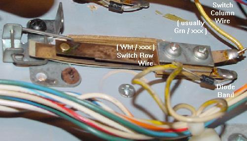
|
Row/Column Problem on the Playfield.
If the row or column problem is isolated to the playfield,
there are few things to look for in solving this problem.
First look for for a short to ground on any playfield switch.
A solder splash or a crushed wire between the playfield and
cabinet are very common.
Next look to see that all the switches in the row/column are
wired correctly (for example, is the diode reversed?) A reversed
switch diode will cause all sorts of switch matrix havoc, such
as phantom switch closures and row/column shorts and confusion.
Another classic problem where an entire row or column does not
work is wires pulling out from the square male/female connector
housings, especially where the playfield plugs into the wiring
harness.
Lastly look at the diode itself and make sure it is not
shorted or open. Playfield diodes (1N4004) can be tested with a
DMM set to the diode function:
- Turn the game off.
- Unsolder or cut one end of the diode from the switch.
- Use a DMM set to the diode function.
- Put the black DMM lead on the banded side of the diode.
- Put the red DMM lead on the NON-banded side of the diode.
- .4 to .6 volts should be seen.
- Reverse the DMM leads, and a null reading should be seen.
- If these values are not seen, replace the diode with a
new 1N4004 diode.
Problem On the Driver Board.
There are several culprits to examine on the driver board.
If a switch column (drive) is stuck on, chips IC17,IC18 (7406)
could be at fault. If a switch row (inputs) is stuck on,
chips IC15,IC16 (4049) may be the problem. Beyond that,
the driver board PIA IC11 (6821) could also be the problem.
Using a Logic Probe to Test the Switch Matrix.
This can be diagnosed further using a logic probe.
Remove connector 2J2 (switch columns).
With the game on and in switch matrix test mode or even just attract mode,
put the logic probe on each pin of connector 2J2.
The logic probe should be pulsing for each pin.
This is the driver board scanning the switch matrix columns.
If a pin is high or low and not pulsing, then the
associated 7406 chip or PIA is probably the problem.
To test the switch rows,
first make sure driver board connectors 2J2 (switch columns)
and 2J3 (rows) are removed. Turn the game on and probe all
the pins of 2J3 (rows). There should be NO activity on the
logic probe! If the logic probe is pulsing, a switch row is
shorted.
Now replace connector 2J2 (switch column)
and connector 2J3 (switch rows).
Using a logic probe, touch connector 2J3 pin 9.
At the same time, try closing a switch in row 1, like the
plumb bob tilt (check the game manual for other switches in row 1).
The pin should pulse when a switch in that row closes, and stop
pulsing when the switch is open (remember there could be other
playfield switches in row 1 closed, so keep that in mind).
If a switch in that row is not close, the logic probe will
show no signal. Note some games don't use row 7 or row 8 of
switches, so don't bother testing those.
Also note using this same technique, if
the logic probe is on connector 2J2 pin 9 (column 1),
a continual tone will be heard, but the tone changes
as the plumb bob tilt switch closes.
Using Leon's Test Chip for the Switch Matrix.
Leon's test chip (as documented in the
Dead CPU section) can also be very
helpful for diagnosing driver board switch matrix problems.
The "tester LED",
as decribed in the Dead CPU section, and
Leon's test EPROM are needed for this.
First, remove fuses F2 and F3 from the power supply before
proceeding. This removes the voltage to the lamp matrix
and all the solenoids. Also remove driver board connectors
2J2 and 2J3 (switch matrix plugs). Then install Leon's test EPROM into
CPU socket IC17 (as described in the Dead CPU section), and
turn the game on.
When using Leon's test chip to test the IC11 switch matrix
chip pins 2-9 on the driver board (switch matrix),
a slight modification is needed to the driver board. On driver board
connector 2J3, short to ground *all* these connector pins
when testing IC11 pins 2-9 (PIA outputs PA0 to PA7). If this is not
done, IC11 pins 2-9 will not alternate on and off.
Use the "tester LED" with the non-resistor lead connected to +5 volts
(TP9 on system6/7 CPU board or interconnector pin 1 on the far right)
and check the PIA chip IC11 (switch
matrix) with the resistor end of the tester LED. Check:
- PIA Pins 2-17,19,39 high then low, alternating on
and off every second.
- PIA Pins 26 to 33 are the data lines, and should be pulsing (use
a logic probe for this).
- PIA Pin 34 (reset) should be high.
If any pin 2-17 are not alternating high then low, then
the PIA is bad. Remove the bad PIA chip, install a socket
and a new PIA 6821 chip.
Leon Testing Switch Matrix "Drive" (Column) Test (2J2).
Again with Leon's test chip running,
connect the tester LED's non-resistor lead to +5 volts
(TP9 on system6/7 CPU board or interconnector pin 1 on the far right).
Using the resistor lead of the tester LED,
touch each pin on driver board connector 2J2.
The tester LED should alternate on and off, in unison with the
blinking LEDs on the CPU board. If the alternating signal is missing
on any connector 2J2 pin, yet all the IC11 PIA signals are present,
IC17 or IC18 (7406) on the driver board has failed.
To verify which input chip IC17 or IC18 is bad, check the input
pins of these chips. Put the resistor lead of the tester LED on
IC17 and IC18 pins 1,5,9,13. These pins feed from the PIA (which
was tested earlier). Now put the resistor lead of the tester LED
on IC17 and IC18 pins 2,6,8,12. If these output pins are not alternating
but the input pins are alternating, the chip in question is bad.
Leon Testing Switch Matrix "Inputs" (Row) Test (2J3).
To test the switch rows, the pins at connector 2J3 will
need to be grounded.
To test row 1, ground pin 9 of 2J3. Using the Tester LED with
the non-resistor end connected to +5 volts,
put the resistor end of the Tester LED on the PIA
IC10 pin 2. The LED should be flashing. Move the ground to 2J3 pin 8,
and check for a flash at IC10 pin 3.
Continue moving the ground down a pin on connector 2J3, and moving
the tester LED up a pin on IC10. The LED should flash should at each step.
If it doesn't, the PIA is probably bad.
"Lane Change" Switch Shorts to the EOS Switch.
Firepower was the first pinball game to use "lane change". This feature
allowed the player to move the lit lamps on the top lanes (above
the pop bumpers), where the
ball feeds from the shooter lane. The lit lamp movement is done with the right
flipper cabinet button (later games used both the right and left flipper
buttons). This is a standard feature on pinballs today, allowing the
user to complete these lane lights easier for increased bonus multipliers,
and to make "skill shots"
on many games (Medieval Madness and Monster Bash come to mind).
The right flipper high-power EOS switch and the low-voltage
switch matrxix lane change switch, doubled up on the same
switch stack. Notice the nylon switch activator, which isolates
the EOS switch from the lane change switch. Also note the
1N4004 diode on the lane change switch wires.
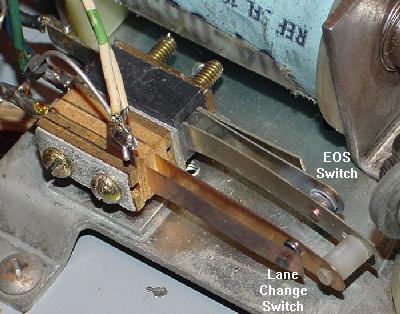
|
Until system11, Williams "doubled up" the EOS and lane change switches
on the same switch stack, and insulated the two switches from each
other (the lane change switch was doubled up with the flipper EOS switch
because it was an
easy way to close a switch when a flipper button was pressed).
The insulation was used because the flipper EOS switch was high voltage at
28 volts (and later 50 volts), and the switch matrix lane change
switch was a low voltage 5 volt switch. If these two switches shorted
together, the driver board's switch matrix circuit (including IC15-IC18
and the switch matrix PIA at IC11) would fry, making the entire game
unusable. This was a very common problem when someone was working
on the flipper EOS switches with the game power on!
The moral of the story is this: Never work on a flipper EOS switch
when the game's power is on!
3h. When Things Don't Work: Score Display Problems
System3 to System6 Six Digit Displays.
All System3 to System6 games (except Alien Poker and Algar) use six digit
score displays. Interestingly, *all* six digits of the score are
lit all of the time. This means a score of 100 points will be shown as
"000100", including the leading zeros. This is kind of weird, but that's
how it was done (other manufacturers also did this on their early
solidstate pinball games).
Late System6 Seven Digit Displays.
With Alien Poker and Algar (both System6 games), Williams changed to
a seven digit score display. Again, all seven digits of the score are
lit all of the time. Also note the score displays on these two games
do *not* use commas, even though the displays themselves support
commas. (System7 games did use the commas.)
The seven digit master display board. Note the use of ribbon cables from
the master display board to the score displays.
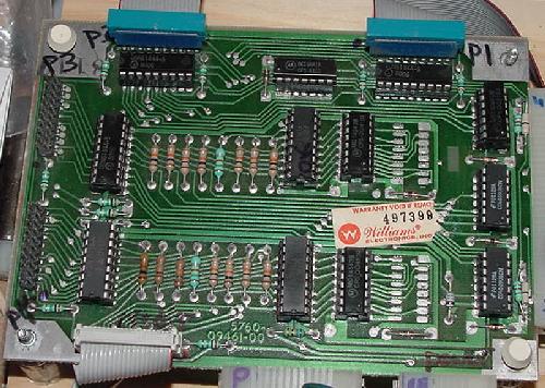
|
System7 Seven Digit Displays.
With System7 things got more sophisticated.
For example, now a score of 100 points showed as "100" in the
score displays (no leading zeros). Also the commas were used (which were
already built into the score displays), so a score of
10,000 points actually displayed as "10,000".
All these "nice touches" on Williams pinballs were largely due
to the introduction of Larry Demar as the lead pinball programmer
in charge of the pinball operating system at Williams.
Originally in all the pinball companies (heck *any*
company which was converting embedded systems to solid
state), the pinball operating system was originally written
by hardware engineers who learned enough assembly language
to get the job done. Then things
languished for years, just building upon that base.
At Williams, Larry Demar approached it from an actual
software and system design standpoint
and tried to do it right. Then once the standard base was implemented
and games were easier to program, Larry started adding cooler
and cooler features (many of which later on became
"standard" on all pinballs by all manufacturers).
This included pinball software
development tools, routines for managing memory and
banked memory, routines for making lamp effects in attract
mode, broken-hardware compensation, auto-percentaging replay
scores, and on and on and on.
The more commonly seen D-8000 six digit master display board which uses
UDN6184A and UDN7180A display driver chips. Note the use of card edge
connectors for the displays.
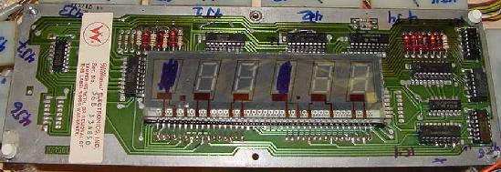
|
The less commonly seen D-8168 six digit master display board which uses
discrete MPS-A42 and MPS-A92 transistors as display drivers. Note the
credit/ball-in-play display is just a standard 6-digit score display, but
two digits are not used! This was unlike the approach taken on 7-digit score
displays for the credit/match unit, where a 4 digit display was used.
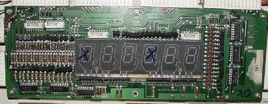
|
Two Versions of the 6-Digit Master Display Board.
Somewhere around late System6, Williams was having a problem
getting the high voltage UDN7180A display driver chip.
To solve this problem, they developed a master display board
with discrete transistors, instead of the UDN7180A chips.
This board is easy to identify, it has a mess of individual
MPS-A42 and MPS-A92 transistors on the board! These board are nice, because the
UDN7180 is an expensive and hard to find chip, where the individual
transistors used to replace the 7180 are easier to get
and easy to test.
My Score Displays are Dead, What Do I Do?
The first thing to check is the score display voltage
on the power supply board. Power supply board connector
3J5 supplies +100 volts, -100 volts, and +5 volts to
the master display panel (which ultimately drives the
individual score displays). If all the score displays
are bad, one should immediately suspect there is a power
problem:
- Power Supply 3J5 pin 1: Logic Ground.
- Power Supply 3J5 pin 3: -100 volts DC.
- Power Supply 3J5 pin 4: 100 volts DC.
- Power Supply 3J5 pin 5: High Voltage ground.
- Power Supply 3J5 pin 6: +5 volts DC.
If any of the above voltages are missing, the score displays
will not work! If one or more is missing, go to the
Power Supply section of this document
for help fixing that. If it's not fuse F1 (1/4 amp slow-blow),
chances are good the high voltage section will need to be
rebuilt on the power supply board.
If there is high voltage (+/-100 volts), now check the blanking
signal. If the blanking signal is low, the score displays will
not come on. A quick indicator is to look at the displays with
the game on. In the corner of the display, is there a very slight
orange glow? If so, the high voltage is getting to the displays,
and the displays themselves are probably Ok.
First check CPU board connector 1J3 pin 4 (which is also TP4). This provides the blanking
signal to the score displays. If this connector is bad or missing,
the score displays probably will not turn on. This connector (upper
left of CPU board) has just one blue/white wire, and that's the
blanking to the displays. With the game off, check continuity from
the CPU board to the master display board. This ensures the
connectors/wire is good. With the game on this wire should have
+4 to +5 volts (indicating the blanking signal is high.)
Sometimes the male header pins crack at the solder joint, so
reflowing this may help.
Also check the
blanking signal itself (pin 37 of the 40 pin interconnector).
The blanking signal should be high (4 volts or higher). If it's
not high, turn the game off and use an alligator jumper wire to tie
pin 37 of the interconnector high to +5 volts. Turn the game
on and see if the score displays light up. If they do, there is
a problem with the blanking signal or blanking circuit. Go to the
blanking section for more information
on fixing this. (Note this can also be done by jumpering TP4 to TP9
on system7 boards.) If this infact does fix the problem, remove
the jumper and fix the blanking signal. Remember the blanking signal
is there to protect the boards. If you have it jumpered high all the
time, you have removed this protection, and bad things can happen
down the road.
If only one score display is bad, the next thing to suspect
is the score display glass itself. These do die, and they
do have a limited life. At $30 to $40 each they are not cheap,
but they are available from the usually parts suppliers.
But please keep in mind, these display glasses can
short internally, damaging the UDN display driver chips on the
master display board, and blowing the high voltage fuse F1.
For this reason, if a score display is completely dead,
I usually replace the score glass first.
Beyond this the next issue is the 6821 PIA chip on the CPU board
at IC18. Leon's test chip can help verify this part.
Check the Master Display Board Resistors.
The next thing to check are the resistor values. With power
off, check the Master Display board resistors
R1-R14 (10K ohms.) Any that are not
within about 10% (9.6 to 10.4k ohms) need to be replaced. Those resistors
can get cooked on the Master display boards (especially if there is a UDN7180
problem). But usually a bad R1-R14 causes single segments to fail on both player
displays one and two or players three and four together, as they
are linked.
Now check resistors R15-R19 (3meg ohms) on the Master Display panel.
These are for the cathode "keep alives", and again should be near that value.
If these are out it will prevent the displays from working at all.
You should see an "orange glow" in the displays when the lights in the room
are off along the bottom edge of each digit at power-up.
These means the "keep alive" signal is working, even if the display is
not showing any numbers.
Check the Connectors.
If you don't see the displays glow and you have verified at
the power supply that it's providing +100v and -100v, check the wiring to the
Master Display board.
With the power off, look for a burnt wire at pins 4J7 pins 1,2,6
on the master display. Sometimes the wires get burnt here. If on System7 games
it will be an IDC connector, and sometimes the wire cuts itself at the connection.
Also look at the connector edges of the Master display board for any burning.
Test the Displays One at a Time.
Another good idea is to disconnect all the player displays 1-4 at the
Master display (with the power off). Power on and check just the Master display board's
credit/ball display first. Then add the other displays back (power off)
one at a time. Use the diagnostic display test and make sure all the digits show
in the displays. Sometimes a short in a display glass can cause "drag down"
the other displays. This will identify any problems like that.
The High Voltage Display Driver Chips/Transistors.
There are high voltage display driver chips
on the D-8000 six digit and all seven digit
master display boards that
control which digit/segment will turn on. These are
high voltage chips, and can often fail:
- UDN7180A : There are two of these on the master display
board. These control the SEGMENTS, with one chip handling
three displays. Note the "A" designation on the 7180, which
signifies a plastic case (instead of ceramic).
- UDN6118A-1/UDN6184A : There are four of these on the master
display board. These control the DIGITS.
The UDN6184A is an older version of
the UDN6118A-1. So it's Ok to replace a 6184 with a 6118.
Note the "A-1" designation on the UDN6118A-1. This
signifies a higher voltage rating than a UDN6118A.
The UDN6118 is a fairly inexpensive and available chip.
There should be no problem finding these, and they are
usually $1 or $2 each. The UDN7180 is a different story.
This is a hard to find chip, and usually sells for $5 to
$25 each! So be careful when working with a 7180 chip.
There is also another version of the six digit master display
board that used version
22 pin NE584/NE585 display drivers instead of the UDN6184A/UDN7180A.
The NE584/NE585 are even more obsolete and rare than the UDN7180A,
so let's hope you don't have one of these boards! They are essentially
unfixable if a NE chip fails. Well that's not entire true.
After checking the datasheets the NE585 can be replaced with an
UDN6118 - leave the 585/584 "feedback" circuit of the NE584 open�
Likewise I think it's also possible to replace the NE584 cathode driver
with an UDN7180.
On the D-8168 six digit master display board sporatically used by Williams
from Flash to the Firepower
era, there are individual MPS-A42 and MPS-A92 transistors instead
of the UDN chips. These transistors can be tested individually and
quite quickly. If there is a problem suspected with this master display
board, I would recommend just testing all the MPS transistors, replacing
any that do not test to the specs below.
Important Note: Testing transistors (or chips) using the methods below
does not give 100% proof that the component is good or bad!
It's probably about 95% accurate, but it is not 100% accurate.
It does show with 100% accuracy if there is a short in the chip.
Testing the UDN7180/UDN6118 Chips and Score Glass for Shorts.
Both UDN chips are 18 pin chips. The four corner pins
of the chips do *not* need to be tested (pins 1,9,10,18).
But all the other pins can be tested. Repeat this test for
each of the UDN6118 and UDN7180 chips:
- Turn the game off.
- Remove the high voltage power supply power connector 3J5.
- Put the DMM on the *diode* setting.
- Connect the red DMM lead to ground.
- Put the black DMM lead on each UDN pin 2 to pin 8.
- A reading of .5 to .7 should be seen.
- Put the black DMM lead on each UDN pin 11 to 17.
- a NULL (no) reading should be seen!
Note if the display glass itself is shorted (it does happen!),
it MAY show up when testing the UDN pins 11 to 17.
So how do we isolate the problem to the UDN chip or the
display glass? First test the UDN chip. If any of the pins
(but mainly pins 11 to 17)
fail the test, desolder the suspect UDN chip from the
master display board WITHOUT DAMAGING IT (these chips are
expensive, and if it's good it would be nice to save the chip from
desoldering damage). Install an 18 pin socket for the chip, and buzz out the
socket making sure there are no shorts, and all traces connect
to the socket.
Now again use the DMM and repeat the
above UDN test procedure ON THE SOCKET (no chip installed). That is,
with the DMM on diode function and the red DMM lead
connected to ground, test pins 11 to 17 of the SOCKET
with the black DMM lead. Again, a null reading should
be seen. If a null reading is seen, the UDN chip has failed
and needs to be replaced. If a null reading is *not* seen, chances are
really good that the score display glass itself is shorted.
If the score display glass fails the test, it will need to be
replaced (there is no way to fix it). After the score display
glass is removed (and before the new glass is installed),
put the UDN chip in the newly installed socket
and retest the chip as described above.
MPS-A42 transistor test:
- Game off.
- DMM set to diode function.
- Red DMM lead on center leg of MPS-A42 transistor.
- Black DMM lead on either outside leg.
- Reading of .5 to .7 should be seen.
MPS-A9 transistor test:
- Game off.
- DMM set to diode function.
- Black DMM lead on center leg of MPS-A92 transistor.
- Red DMM lead on either outside leg.
- Reading of .5 to .7 should be seen.
On System3 to System6 master display boards, resistors R1-R14 (10k 1/2 watt)
often burn. If this happens, a segment on the score display will not work. Here
R11, which is disabled, shows the missing lower segment of the player 3 score
display.
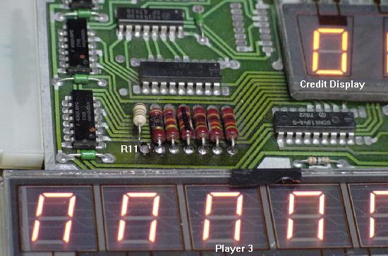
|
Partially used System3-6 UDN7180 Chip.
System3 to System6 master display panels only uses half of the UDN7180 at IC4.
For example you can bend up IC4 pins 2,4,6,8,11,13,15,17 and the
displays will still work fine. So if you have a UND7180 that is "half bad",
putting it at IC4 may make the chip usable for System3-6 games.
Logic Probe Test Tip.
Through out this section a logic probe is mentioned for finding
problems in the UDN chps. The problem with using a logic probe
is it tests low voltage. Score displays are anything but low
voltage, and 100 volts will ruin a logic probe. The best way
around this is to turn the game on and get into the score display
diagnostics test feature of the game (where the game is repeating
"000000", "111111", etc). Then remove the two
high voltage fuses from the power supply. This will cut the
-100 and +100 volts going to the master display panel. Now a
logic probe can be safely used on the master display panel
with any damage to the logic probe.
Missing Segments - UDN7180.
If segments are missing from a score display, this
will usually be either a bad resistor at R1 to R14
on the master display board, a bad UDN7180 chip, or
a broken lead going into a score display glass.
The segment resistors R1-R14 should be tested first.
It is very common for these to burn.
They can be tested easily in-circuit using a DMM (10k ohms,
1/2 watt). Replace any that are more than 10% out of spec.
The UDN7180 is not as easy to test. But it can be tested
with a logic probe. Just check the input pins of the UDN7180A
(pins 2,3,4,5,6,7,8) for pulsing activity. This If there is no
activity, either the master display board's connector is
bad, or the input chips (4558) are bad.
Now test the UDN7180 output pins (pins 14,15,16,17,18,19,20)
for pulsing activity. If there is input activity, but no output
activity, then the 7180 is bad.
On system3 to system6 SIX digit master display boards,
the UDN7180 control:
- IC9 = Credit/ball-in-play, Player1, Player2 segments.
- IC10 = Player3, Player4 segments.
On system6/7 SEVEN digit master display boards,
the UDN7180 control:
- IC2 = Credit/ball-in-play, Player3, Player4 segments.
- IC1 = Credit/ball-in-play, Player1, Player2 segments.
Locked On Segments - UDN7180.
Locked on segments can also be a problem with a UDN7180A chip
(shorted internally).
But more common is something simple like a solder splash or
solder bridge on the master display board.
Burning Resistors R1-R14.
These 10k resistors often burn on the master display board.
But just be aware that if you replace them with new 1/2 watt
resistors, and they burn again, the problem could be a bad
score display glass. To diagnose this, try running the game
with just the player one score display only, and see if
the resistor(s) burn. If not, connect the display back one
at a time until the resistor in question starts to burn again.
This should help determine if you have a bad score display glass.
More Strange Display Problems.
A user emailed with a Black Knight that had different score
digits/segments starting to burn, while others
appeared faded or not at all. Replacing MPU board chip
IC6 (74154) fixed the problem. Remember a bad 74154 chip will effect digits
on both players 1 & 3, or players 2 & 4.
Missing Digits - UDN6184/UDN6118 and CPU board 74154.
If digits are missing from a score display, this
will usually be either a input 4069 chip
on the master display board, or a bad UDN6184/UDN6118 chip
on the master display board. If you know the master display
board is OK (tested in another game perhaps or swap the display
cables to a different display if possible), it could
also be a problem on the CPU board, the
74154 chips. But remember a bad 74154 chip will effect digits
on both players 1 & 3, or players 2 & 4.
The UDN6118 can be tested just like the 7180 above, with
a logic probe. Just check the input pins of the UDN6118
(pins 1,2,3,4,5,6,7,8) for pulsing activity. This If there is no
activity, either the master display board's connector is
bad, or the input chips (4069) are bad.
Now test the UDN6118 output pins (pins 11,12,13,14,15,16,17,18)
for pulsing activity. If there is input activity, but no output
activity, then the UDN6184/UDN6118 is bad.
On system3 to system6 SIX digit master display boards,
the UDN6184 control:
- IC4 = Credit/ball-in-play display digits.
- IC11 = Player 1 and Player 2 digits.
- IC12 = Player 2 and Player 3 digits.
- IC13 = Player 3 and Player 4 digits.
On system6/7 SEVEN digit master display panels,
the UDN6184 control:
- IC7/IC8/IC12/IC13 = Credit/ball-in-play display boards.
- IC13 = Player 1 digits.
- IC12 = Player 2 digits.
- IC8 = Player 3 digits.
- IC7 = Player 4 digits.
"0_0_0" on the Score Displays.
If the score displays are only showing three of the six (or seven)
digits of the score, this is usually not a problem with the master
display panel. Instead this is a driver board PIA problem. If the
lamp PIA (IC10) and/or solenoid PIA (IC5) have failed, this problem will often
be seen. Unfortunately using Leon's Test ROM does not find this
problem (Leon's Test ROM will often show these two PIAs as "good"
even though these two PIAs are responsible for this problem).
Score Display Glass - Problems and Tips.
The score display glass can short internally. This usually will blow
the +100/-100 volt fuse on the power supply board. But in the
process it can also destroy a UND7180 and UDN6184 chip(s).
A good way to diagnose this problem is this: with the game off,
disconnect all the score display glasses from the master display
board. Replace the blown +100/-100 voltage fuse F1 on the power supply
board with the correct 1/4 amp slow-blow fuse (do NOT over fuse!)
Turn the game on. If the fuse doesn't blow, turn the game off
and add ONE score display back to the master display board. Turn the
game on again and check the F1 high voltage fuse.
Keep repeating this, adding one more score display glass each time,
until the high voltage fuse blows. This will identify exactly which
score display glass is shorted. Once found, replace the display glass,
and hope no UDN chips were ruined.
The unique system7 four digit score glass used for the credit and ball-in-play
displays.
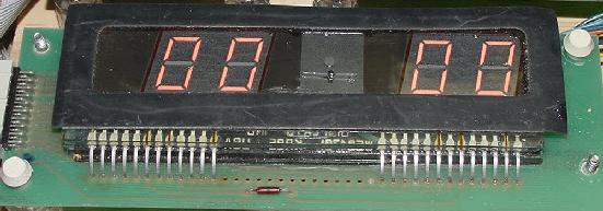
|
Also it should be mentioned that on the 6-digit score
display glass, the credit/ball-in-play display used a standard
six digit glass. The only difference was two of the six
digits in the glass were not used. On games with seven digit
displays, the situation was different for the credit/ball-in-play
display. This was not a standard seven digit display with
unused digits, but a unique 4-digit score glass. Unfortunately,
these are VERY hard to find. So it's best to hope this display
glass is not "outgassed".
Another interesting factoid is that the new replacement seven
digit display glasses have the rear "nipple" mounted in the wrong
position! (Williams has a hole in the score display circuit board
to accomodate the "old" position of the nipple, which apparently
the current manufacturer of score display glasses moved.)
This means the display circuit board needs to be drilled
for the new nipple position, and some components and board traces
re-routed.
Score Glass Longevity: Replace Power Supply Diodes Z2,Z4.
Power supply board diodes Z2 and Z4 should be changed from
1N4764 (100 volts) to 1N4763 (91 volts). This change will
make the score displays slight dimmer, but it will also
dramatically increase the life span of the score displays.
Again see the
Power Supply section of this document
for more details.
Fading/Scrolling Score Displays.
If the score displays on a System3 to System7 game slowly fade in a
scrolling fashion, check the high voltage C1/C3 (100 mfd 150 volt)
filter capacitors on the power supply board.
3i. When Things Don't Work: Sound Problems
Sound Board Introduction.
The first two solidstate Williams games used EM-style chimes for
sound. But by World Cup, Williams' third system3 games, a sound
board was incorporated into the lower cabinet to produce electronic
sounds.
Williams was actually a bit paranoid about their new solidstate
games, and if players would accept them. To ease the transition,
the first two system3 games (Hot Tip, Lucky 7, and some very early World Cups)
had a "noise maker". This a score reel mounted in the lower
cabinet, to make EM-style noises when the game played! The score reel
coil was driven by a driver board transistor, just as the sound chimes
were. Williams added the score reel to
make their new solidstate games sound like old EM games, which many
players were used to. By early production of World Cup, Williams stopped
adding the score reel.
On system3 to system6 games, sounds are actually triggered by
solenoid transistors on the driver board. When a desired sound
was needed, a solenoid driver transistor was used to ground a
pin on the sound board. There were five driver board transistors
dedicated to sounds, but more than five sounds existed.
Different sounds are created when a combination of these five sound
drivers were pulled together at once. Basically there are a total
of 32 different sounds possible, which is 2 to the 5th power (so
32 different sounds can be triggered when any of the five sounds are
either on or off at the same time).
Interestingly, all versions
of the System3 to System6 sound board had the same pinout. Also all
the sounds were activated by the same driver board solenoid numbers (except
for World Cup and Disco Fever which had some additions, and all the
shuffle alleys):
- Sound 0: driver solenoid 9 (Q31) to 2J9-9, to sound board 10J3-3.
- Sound 1: driver solenoid 10 (Q33) to 2J9-7, to sound board 10J3-2.
- Sound 2: driver solenoid 11 (Q35) to 2J9-1, to sound board 10J3-5.
- Sound 3: driver solenoid 12 (Q37) to 2J9-2, to sound board 10J3-4.
- Sound 4: driver solenoid 13 (Q39) to 2J9-3, to sound board 10J3-7
(10J3-8 on early games World Cup & Disco Fever).
- World Cup: solenoid 7 (Q27) to 2J11-2, to sound board 10J3-6.
- World Cup/Disco Fever: solenoid 15 (Q43) to 2J9-5, to sound board 10J3-7.
When System7 came with Black Knight, driver board transistors were
no longer used to trigger sounds. Instead the System7 CPU board had
an additional PIA chip at IC36 which triggered the sounds (this freed
up the driver board transistors for coils instead of triggering sound). The sounds
were still generated by the same sound board in the same manner though,
using the same pinout. Grounding sound board connectors 10J3 pins 2,3,4,5,7. Just this was
now done by the CPU board's extra PIA chip at IC36 (and a new
connector on the CPU board at 1J8). Here's the system7 CPU connector 1J8 pins.
Note this connector also handles commas for the score displays:
- 1J8 pin1: Comma for displays 3 & 4 (Brown/White)
- 1J8 pin 2: Comma display players 1 & 2 (Violet)
- 1J8 pin 3: Key pin
- 1J8 pins 4-7: No Connection
- 1J8 pin 8: Sound Select 4 (Yellow) to sound board 10J3-7
- 1J8 pin 9: Sound Select 3 (Green) to sound board 10J3-4
- 1J8 pin 10: Sound Select 2 (Blue) to sound board 10J3-5
- 1J8 pin 11: Sound Select 1 (Red) to sound board 10J3-2
- 1J8 pin 12: Sound Select 0 (Red/Yellow) to sound board 10J3-3
With the sound board connector pinout info, some (not all!) of
the individual sounds can be triggered by momentarily grounding the
sound board Sound Select pin. You won't get all sounds this way
(many sounds are triggered from a combination of pins being grounded),
but at least you can do some prelim tests on the sound board. Also
helpful is of course the sound board test switch, which should
fire off most of the sounds at any time.
Another quick test on system3-6 games is to ground the
driver board transistors that drive the sound. This will confirm
if there is continuity from the driver board transistors/connector
to the sound board. These driver board transistors are along the
lower left edge of the board. Here's a chart that shows which
transistors to ground for sound test for coil# 9-13 (which are
the sound driving coils):
Sys3-6 Sound
Driver board
connector |
"Coil" Sound Numbers of
the Two bottom rows
of driver transistors |
| 2J9 pins 7,9 |
Coil#10
Snd#1 |
Coil#9
Snd#0 |
Coil#6 |
Coil#7 |
Coil#8 |
| 2J9 pin 1,2,3 |
Coil#11
Snd#2 |
Coil#12
Snd#3 |
Coil#13
Snd#4 |
Coil#14 |
Coil#15 |
Bold are the sound driving transistors
Remember these TIP120 (replace with a TIP102) transistors along
the bottom edge of the driver board take a lot of "handling"
abuse if the driver board is removed. I often see these transistors
with broken leads from being moved back and forth. Also check the male driver board connector
2J9 for cold solder joints (very common), and the male sound board connectors too.
Have the wrong sounds being made? This is usually a problem with the driver
board on system3-6 games. Remember I mentioned that many sounds are produced
by a combination of the five sound inputs being grounded at the same time.
With this info there are a total of 32 sound possibilities (really 31, because "0"
is a null sound). If the wrong sound is being made, often that's because one
of the sound inputs is either not being grounded, or is stuck to ground.
This is most often caused by a bad (or missing!) driver board transistor or connector.
Again grounding the driver board transistor metal tab is a quick and easy
way to check continuity to the sound board. Also test the transistors with a
DMM set to diode test to confirm they are good (the coil problem section of this
document helps with that.) And remember
on system7 games, missing/wrong sounds could be a CPU board PIA problem (using Leon's test chip
can confirm the PIA as good).
Sound Board Files.
System3 to System6 games all used four different sound EPROMs
for their sound board. These 2716 sound files were traded between
the games, and implemented slightly different in each game.
These four EPROM files were labeled "Sound", "Sound1", Sound2", "Sound3"
(though the download files often refer to them as Sound1-4, infact
the files are names as shown above.)
Here's a rundown of the EPROM files uses for the sys3-6 games:
- No Electronic Sound:
- Hot Tip (sys3)
- Lucky Seven (sys3)
- SOUND
- SOUND1
- Contact (sys3)
- Disco Fever (sys3)
- Flash (sys6)
- Laser ball (sys6)
- Phoenix (sys4)
- Pokerino (sys4)
- Scorpion (sys6)
- Steller Wars (sys4)
- Time Warp (sys6)
- Tri-zone (sys6)
- World Cup (sys3)
- SOUND2 (works with speech files and newer type2 sound board)
- Blackout (sys6), speech
- Gorgar (sys6), speech
- SOUND3 (works with speech files and newer type2 sound board)
- Firepower (sys6), speech
- Alien Poker (sys6), speech
With System7 the new type2 sound board was alway used, but
only sometimes with the ribbon-cable attached speech board (where speech is needed).
These games mostly each had their own custom sound board
EPROM file, but five games did recyle the same sound EPROM.
- Junglelord (speech), sound ROM3
- Laser cue (no speech), sound ROM3
- Algar (no speech), sound ROM4
- Baracora (no speech), sound ROM4
- Hyperball (no speech), video sound ROM4
- Joust (no speech), video sound ROM4
- Black Knight (speech), sound ROM5
- Pharoah (speech), sound ROM6
- Solar Fire (no speech), sound ROM7
- Cosmic Gunfight (no speech), sound ROM12
- Firepower2 (no speech), sound ROM13. Firepower speech can be added.
Use the Firepower speech board and ROMs, connect as usual to the FP2 sound board via
ribbon cable (if the ribbon cable connector is missing on the FP2 sound board,
add it.) Then cut sound board jumper W1. Speech calls are in the correct place
and this does work very well.
- Time Fantasy (no speech), sound ROM13
- Warlok (no speech), sound ROM14
- Defender (no speech), sound ROM15
- Varkon (no speech)
The interesting thing about the EPROM files is this:
they all work in either a Type1 or Type2 sound board.
That is, you can put the Firepower (type2) sound 2716 EPROM
in the older type1 sound board and it works just fine
(obviously no speech though). So if you really had the
sound for any game, you can change it to some other
game's sound package. Also on many of the download files
the sound files are just generically named, even though
the sound files are different (as indicated above). And
Alien Poker is often wrong (it is sound ROM3).
Sound Board Basics - Its Own Computer.
All versions of the System3 to System7 sound boards operate
in the same manner. The sound board is basically a stand-alone computer.
Its brain is a 6802/6808 CPU chip, and also has a single 6810 static
RAM chip, and its own 6821 PIA (Peripheral Interface Adaptor) chip,
and a 2716 or 2532 EPROM which holds the program code.
There is a reset section just like the main CPU board, and the boot
up process for the sound board is very similar to the boot up
process for the main CPU board.
For example, pin 40 of the 6802/6808 CPU chip is
held low at power-on for a moment while the +5 volts stablizes. Then the CPU reset
pin 40 goes high.
There is a clock signal at pins 38,39 of the 6802/6808 that also
must be running, from the 3.58 mHz crystal.
If the CPU chip's pin 40 is high, and the clock is running at
CPU pins 38 & 39, the program code stored in the sound board's EPROM
is run (assuming all the address and data lines are present between
the CPU, PIA, RAM and EPROM).
The sound board also has its own +5 volt power supply. The transformer
supplies 12 to 18 volts AC to the sound board connector 10J1, which goes through a small
bridge rectifier and a filter capacitor. Unregulated +12
and -12 volts DC is produced in the process. The unregulated
+12 volts goes to a 7805 voltage regulator, producing a regulated +5 volts DC
just for the sound board. Remember there are also one or two fuses on the
sound board for the incoming AC power.
System3/4 sound board (known as TYPE 1), located in the lower
cabinet, and in the backbox of some early System6 games. Note the
SW2 sound select switch, and the SW1 test switch.
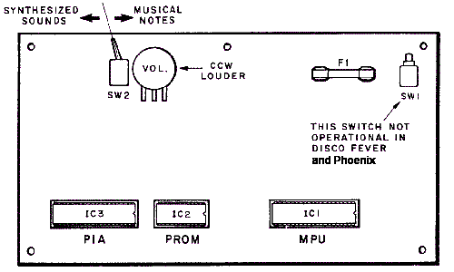
|
System3 Sound Switch.
On the early sound boards (the long rectangle boards used on System3 and
System4, and mounted in the lower cabinet),
system3 sound boards have a red toggle switch.
This toggle switch controls the two types of sounds
the board can generate: musical notes ("chimes") or synthesized ("electronic")
sounds.
For example World Cup has one of
these sound boards with the red switch.
This sound board can switch from
"electronic" to "chime" while the game is on (the sounds are not
just different, so are the "songs" played). But once switched to
"chime", it can only be switched back to "electronic" by powering
off the game.
As a further note, on some games this sound board switch is also wired back
to the driver board. It appears the intent was to allow the gameROM
software to change the board to chime mode, even if the toggle switch
was set for electronic sounds. It does not appear this feature was
ever implemented though. This is why some of the early system3 games
have more than five driver transistors connecting to the sound board.
System6/7 Speech & Sound boards (known as sound board TYPE 2), located in
the backbox.
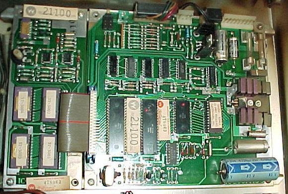
|
System6/7 Sound Switches.
The backbox mounted sound board used in late system6 and system7 games
also has a sound select switch in the form
of a small two position DIP switch. This switch is used to determine if
an attached speech board is to be used (note the sound board must be
jumpered correctly to use a speech board, this information is covered in
the CPU/Sound Board Jumper section, but basically
sound board jumper W1 must be removed to use the speech board).
For games that use speech (Gorgar, Firepower, Blackout,
Alien Poker, Black Knight, Jungle Lord and Pharoah), this
two position DIP switch much be set correctly, and jumper W1 removed
from the sound board. These games
use a speech board, which attached to the sound board with a ribbon
cable.
Switch 2 of the
DIP switch must be set ON for speech (OFF would be for sound only, no speech).
Switch 1 of the DIP switch, depending on the game, can be set on or off, depending
if synthesized or musical notes are desired (only applicable
if DIP switch 2 is set OFF, for sound only). For games with speech, I generally
set the DIP switches so the top switch #2 ON, and the bottom switch #1 OFF (for
true Synthesized sounds, and not those dumb "bongs").
But verify with the game manual if this correct for the game title in question.
The Sound Board Test Switch.
All system3 to system7 sound boards have a push button test
switch on the sound board. If this is pressed, a checksum of the
sound board EPROM is done, and usually most (if not all)
of the sound board sounds will then play in a continuous loop.
This is the easiest way to test a sound board. There should be
no pauses between the sounds. If there is, chances are good that a
sound is missing (meaning the sound board can not access a
particular sound stored in an EPROM). To stop the test,
turn the power off (sorry, that's the only way!)
Note early sounds boards (system3/4) may just emit a continuous
sine wave with the sound board test button is pushed.
Again the only way to abort this is to power the game off.
Also on some early games (Disco Fever, Phoenix), this test switch
may do nothing.
What if the Sound Board Doesn't Work at All?
Check the Sound Board Voltages.
First check for +12 vdc, -12 vdc and +5 volts on the sound board.
There should be four test points (including ground) for easy voltage testing.
If any of these voltages are missing, the sound board will not function.
Of course first check the fuse(s) on the sound board.
Sometimes the sound board's bridge rectifier can short or go
open, or the 7805 voltage regulator can short (if the 7805 regulator
shorts, this can send 12 to 18 volts down the 5 volt buss, which
usually takes out the EPROM(s), CPU and often the 6821 PIA and
6810 RAM chips). Hopefully at least one of the sound board fuses
will open if this happens.
Turn the Volume Up - Check the Amplifier.
With the game on, and proper voltages on the sound board,
turn the volume pot up all the way. At minimum, some static
should be heard. If there is absolutely no sound, then the
TDA2002 amplifier chip is not working. Before proceeding
any further, this must be fixed first!
Check the Speaker, Pot, and Audio Amp Solder Points.
If absolutely no sound is heard, it could
be as simple as a bad 8 ohm speaker. Also the 5k volume pot can get dirty
and form "dead spots". Turn the pot back and forth several times with
the game on and listen for a change (spray contact cleaner can be used
to clean the pot, with the game off).
Another common problem is the
solder joints crack on the sound amplifier (TDA2002). Because the amplifier
component sticks out from the sound board and has a large heat sink
mounted to it, vibration can crack the solder joints. If this happens,
the amplifier won't work, and no sound will be produced! Resolder
the amplifier (it looks like a five legged transistor) on *both* sides
of the sound board.
If there is definately +12, -12 and +5 volts on the sound board yet
no noise is made, replace the TDA2002 amplifier.
Sound Board Test Works, but Missing Sound in Game.
Sometimes there will be a problem where the game is powered on,
sound test button pressed, and all the sounds (and speech)
work. But in game mode the sounds don't work. Usually this is
a 6821 sound board PIA problem, or maybe a 6810 problem. But here's some
things to try:
- Verify with a logic probe that the 5 signal lines to the
sound board are all pulsing low when cycling through solenoid tests 9-13.
- Grounded each signal pin at the sound board and see if sounds are produced.
- Measure the associated pins on the 6821 when you're grounding pins on the
sound board connector pins.
- Check sound board IC6 pin 13 (4068). It should pulse high whenever you
ground a pins on the input connector.
- Check sound board chip 6821 pins 37/38. If it's working,
the /IRQ will go low when you ground input pins.
Example: Pinrepair user K.Nelson had a Gorgar that was
missing two sounds in the game, and that played the wrong
sounds during game play. Using the game's solenoid test he
found solenoid sounds 9/10 were not working. Yet pressing the sound board's
red test switch played all sounds.
To make sure the driver board was not the problem, he ran
a jumper wire from the driver board solenoid9 connector pin
to one of the sound board inputs he knew was working. And
sure enough, the game triggered this sound no problem in
the diagnostic sound test. So he knew the problem was on
the sound board. Turns out after replacing the 6821 PIA on
the sound board, the problem was fixed.
Sound Board Jumpers.
On system6 and system7 sound boards, be sure to check that the
board is jumpered correctly, especially if the sound board
was transplanted from another game. This information is covered in
the CPU/Sound Board Jumper section.
Troubleshooting a Non-Working Sound Board.
Assuming the sound board voltages are present and the
amplifier is working, the next thing to check is
that the 6802/6808 CPU chip's pin 40 is high. If it is, this
signifies the reset section of the sound board is working.
Next, using a logic probe, check for a clock signal at the CPU
chip pins 38,39. If that is missing, the crystal or associated
capacitor is probably dead.
After all that has checked out Ok, next suspect the sound card
sockets. Just like the CPU board, "Scanbe" sockets were also
often used on the sound and speech cards. By default, just like
the CPU board, these sockets need to be replaced. Sorry, it's more
work, but there's nothing that can be done other than to replace
these sockets.
At this point, turn the game on and turn the volume control up.
Is there at least a small amount of static coming from the speaker?
If so, this signifies that the sound board's audio amplifier is
working, which is a good sign. If no static or hum is heard,
and all the voltages are present, the audio amplifier (TDA2002) could
be blown.
If the sound board is still not producing sounds, now it's time to
replace the sound board EPROM(s) (see below for more details).
An EPROM programmer is needed for
this. Still no sound, swap out the 6821 PIA chip with another known
good chip, and try the same thing with the 6810 static RAM chip.
Low or Really Low Volume on System6/7 Games.
Aside from the 1458 pre-amp chips themselves, there are two capacitors that are in direct line
with the output of the 1458 pre-amps. One is a 10mfd caps (after the 1458 chips),
and the other is a 1mfd (before the 1458 chips.) If either of these electrolytic
capacitors fails, very low (to nearly no) volume will result. Unlike most of the
capacitors on the system6 and system7 sound board, these caps are in direct line
with the volume signals (opposed to filtering to ground.) So any problems with
either of these capicators, and low to no volume is the result. (Note the 1458 chips
can fail too, but frankly this is far less common.)
Using Leon's Sound Board Test Chip and Other Testing Methods.
The sound board can be powered on the work bench (or in the game, but
it's easier to work on the bench). To do this, again use an old computer
power supply (as discussed in the CPU board test section) that
output both +12 *and* -12 volts. If this is not available, a
small transformer taking 120 volts AC down to 12 volts AC would
also work fine. Because many people won't have these types
of power supples, the game can also be used to power the sound
board. Just pull fuses F2 and F3 while doing the test. Also
remove connector J3 from the sound board. Sound board connectors
J2 (speaker), J4 (volume control), and J1 (power) should stay connected.
If doing this on the bench,
connect ground to sound board connector J1 pins 5 or 6,
+12 DC to J1 pins 1 or 2,
and -12 DC to J1 pins 8 or 9.
Don't forget to connect a small speaker to J2 pins 2 and 3.
Jumper J4 pins 1 and 2
together so a volume pot is not needed.
If the game is a system6/7 sound card with an added speech card,
remove the speech card. Then add jumper W1 to the sound card
(when all done with the test don't forget to remove jumper W1 and
reattach the speech card). Jumper W1 is important to add, otherwise
the sound board will not work properly without its attached speech
board.
First measure the signals on the IC1 (or IC9 on sys6/7)
CPU chip (6802/6808). Remove the EPROM from the sound board
at IC2 (IC12 on sys6/7) and connect power.
Here is what should be measure with a DMM set to DC volts:
- CPU Pins 2,3,4,6,8,38 = +5 volts
- CPU Pins 5,34,40 = +4 volts
- CPU Pins 9-20,22,23,24,25,37 = +2 volts (pulsing)
- CPU Pins 21,26,27,28,29,33,36 = 0 volts
- CPU Pins 38,39 (clock signal) = .2 volts
If any of the above voltages are wrong,
check if its an output or input signal. If it's an output
like an address line then the CPU IC has usually failed.
If it's an input signal then check the schematics to see
what chip it comes from. Remember
pin 40 (reset) gets 5 volt through a delay circuit of 2 transistors.
If it's missing then replace those two transistors.
At this point if the sound board is still not working, it's
time for the heavy-duty testing to begin.
Our buddy Leon has developed a sound board test chip that is very
similar to his
CPU board test chip
(thanks Leon!) This is a ROM file that
can be downloaded here and burned
into a 2716 EPROM. This test chip will work on any system3 to
system7 sound board, and will test the sound board's 6821 PIA chip
at IC3 (IC10 on sys6/7).
After obtaining the test EPROM, plug it into socket IC2 (IC12 on sys6/7)
on the sound board (there is only one ROM socket on any system3 to system7 sound
board). Note early system3/4 sound boards MUST be jumpered for a 2716 for this
chip to work, as the board could be jumpered for a 512 byte PROM
(this is described in the CPU/Sound Board Jumper
section).
The "tester LED" construction.
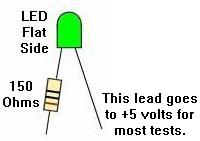
|
With the EPROM installed and power turned on to the sound board,
use a test LED shown above and as described in the CPU testing section.
Connect the test LED non-resistor portion to +5 volts, and touch
the resistor lead to pin 15 of sound board CPU chip IC1 (or IC9 on
type 2 system6/7 sound boards). If all is working, the tester LED
should be flashing on and off about once a second.
Now move to the PIA chip IC3 (IC10 on sys6/7), and check the PIA outputs.
These should also be alternating on and off once every second with the
tester LED:
- PIA Pins 2-17 high then low (tester LED on and off), alternating
every second.
- PIA Pins 26-33 are the data lines, and should be pulsing (use a
logic probe for these pins).
- PIA Pin 34 (reset) should be high (tester LED on).
If the PIA pins 2-17 are not turning on and off with the tester LED,
chances are very good the PIA 6821 chip has failed.
Is there one missing then unsolder this PIA pin and bend it up
or cut the trace. If the output now turns on and off, then
there is a short on the board. There are only three possible chips
connected IC6,IC8,IC9 (IC13,IC5,IC6 system6/7 type2 sound board).
Check the schematics to see which chip is connected to this output.
If the output of the PIA is stil bad then the PIA itself has failed.
On type2 sound board (system6/7), Leon also has a memory test.
With his test EPROM installed and running and all the PIA outputs OK,
his chip will test IC11 (6810), which only exists on system6/7 sound
boards (obviously this test doesn't have to be done on type1 system3/4 sound boards).
Start the memory test by pushing sound board push switch SW1 during the PIA test.
If the memory test passes, the tester LED will start blinking again.
If the memory has failed then the tester LED will stay dimmed (the
test will keep on running and testing the memory until it's found to be good).
This way it is possible for us to test
the signals with a DMM set to DC volts on the IC11 (6810) chip:
- IC11 Pins 1,14,15 = 0 volts
- IC11 Pins 2-9,13,20,21,22,23 = 2 volts
- IC11 Pins 10,24 = 5 volts
- IC11 Pins 11,12,16 = 3 volts
- IC11 Pins 17,19 = .5 volts
Signals which differ from above will need to be traced
Usually the signals will be ok and the memory chip IC11 has failed.
To verify the sound board as working, replace the Leon test EPROM
with the game ROM, and power the sound board on. Press the sound
board test switch, and some sound should be produced.
Fixing a Bad Speech Board.
On system6/7 type2 sound boards with speech, this board was
removed in the above tests. If the sound board is now working
and tests good, remove sound board jumper W1 and re-connect
the speech board (with the power off). Power the sound board
on and press the test switch. If the sound board no longer
works, then there is a problem with the speech board!
Assuming the speech board EPROMs are good (these 2532 EPROMs
often fail),
if there is sounds but no speech then the speech board mixer
chip IC2 is probably OK.
If there is no sound then it's almost certain speech board IC2 has failed.
Speech board IC3 should only be replaced as a last resort,
as this is the speech amplifier. The entry and output passes through
capacitors which offers protection against voltage spikes.
After that, the only chip left is IC1 on the speech board.
No Speech - A Simple Modification to the Speech Board.
Often the speech board needs a small modification to work.
This mostly applies to those speech boards using the 55536 speech chip
instead of the 55516. If a newer speech board with the 55536 chip
is used in a system6 or system7 game, the speech may not work.
To fix this,
put a .01 uF cap between the speech clock and
ground, using the plated through hole and solder it on the back
side of the board, and then connect the other leg of the cap to IC5 pin 12
(upper right PROM from the front of the board). This will often fix
many speech related problems because it increases the speech trigger length.
Summary of No Speech Issues.
If the game does not have speech (assuming it should have speech),
there is an easy test to see what could be the problem. Clive summarizes:
With the game on press the diagnositc switch on the sound board.
If there is a pause in the test where the speech should be (that is,
silence), then the speech ROMs, 1458's, or the speech pot is the likely issue. If
the sound test loops with no speech and no pause where the speech should
occur, then it's 99% likely that there is a bad ribbon cable between
the sound and speech board.
This is because the selftest ignores the speech board if it cannot "see" the speech ROMs.
If this is the case, the sound board drops them from the test loop, hence
there are no pauses.
In addition, other things that can cause no speech include (pretty much in this order):
- Bad electrolytic sound board caps
- Bad speech board op-amp(s)
- Bad speech board ROMS
- Bad sound board trim pot for sound/speech balance
Speech board modification. Pic by Eric.
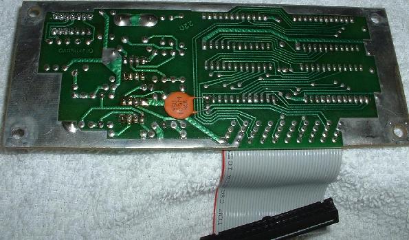
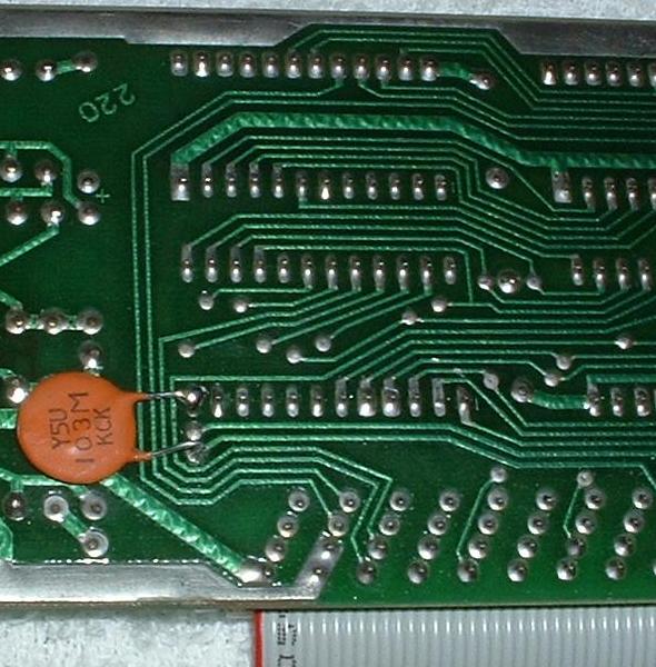
|
Missing Sound or Speech - Bad Connectors, EPROMs, and Sockets.
If one of the five sound "bits" are locked on/off (as discussed above in
the sound board introduction section), a sound or speech word
could be missing. The most obvious indication of this is when, for example,
Gorgar says, "Gorgar Beat", and then not the "Me" to complete the phrase.
One of the first things to do on games with speech is to
isolate the sound/speech board from the CPU/Driver board
(remember the sound/speech board is its own computer).
This is easy to do, just power the game off and remove sound
board connector 10J3. Now power back on and press the test
button on the sound board, which will test the board without
any interference from the CPU/Driver board. If the game
plays just sounds (no speech) with *no* pause between sounds, then it's
sensing a problem on the speech board. Or if sounds are just heard,
but with a pause between each some sounds, or garbled/static noise between
some sounds, then that usually means a problem with speech ROM data,
or maybe even a component problem on the speech board.
Don't forget to
check the settings of the two DIP switches in upper left corner of sound
board, and make sure all the speech ROMs are in the right positions (sockets)
on the speech board. Also make
sure speech board's ribbon cable is connected to sound board securely.
If there is a missing speech word or sound, this could be
from a cracked header pin connectorn 10J3
on the sound board. These .156" Molex male
header pins on the sound card's connectors often crack. Resolder these
at minimum,and replace any that look corroded or tarnished.
On system3 to system6 games, also check the driver board connector 2J9
and its header pins, which feeds sound board connector 10J3.
On system7 games, check CPU board connector 1J8
and its header pins.
It could also be a bad sound and/or speech board EPROM(s).
If one sound or speech EPROM is bad, either there will be no
sound or speech, or some words/sounds will be missing or garbled. Often
a bad EPROM will allow the games to say partial phrases like,
"Gorgar Beat", and then not the "Me" to complete the phrase.
When the sound board can not complete a phrase, it will
just shut down the audio, because the speech data is corrupt
or missing.
The old black ROMs use silver legs, and can often tarnish and
break off. Of the ROMs can get "bit rot", and just not work.
It's a good idea to replace them with new EPROMs.
The speech boards up to system7 used up to four 2532 EPROMs
(side note: system9 games like Space Shuttle used the same
basic speech board, but changed to 2732 EPROMs).
The sound board uses a single 2716 or 2532 EPROM.
There could also be bad EPROM socket(s). Again, if the sound/speech board
uses SCANBE sockets, they should *all* be replaced.
Usually the best approach is to replace all the scanbe sockets on
the sound and speech board, and then re-evaluate the problem.
If the problem still exists, then burn a new set of speech
EPROMs for the board, and re-test.
Testing the Sound Board's Sound Inputs.
Try these steps for a simple sound board test:
- Turn the game on.
- Press the "self test" button on the sound card.
- Sounds and speech should be heard continually
with NO breaks in the sound or speech (may not work on Disco Fever & Phoenix).
- To exit the sound test, turn the game off (yes that's
the only way to exit the sound test!)
After doing the above, try this:
- Turn game off.
- Remove sound board connector 10J3.
- Turn the game on.
- Using a test lead with one end connected to ground,
touch the following sound board pins (one at a time)
to ground: sound board connector J3 pins 2,3,4,5,7 (remember pin 1 is
the "key", and is missing).
- A different sound or speech clip should be heard for each of the five
grounded pins 2,3,4,5,7. If missing a sound from any of the pins,
and the sound/speech EPROMs have been replaced,
a problem lies on the input select side of the sound card.
If a sound is still missing, there is one more thing
that should be tried. That is to swap around the PIA
on the sound board with another 6821 PIA (could swap one
from the driver board).
If all the sounds are present in the above test, but
sounds are still missing in game play, the problem may be on
the driver board (system3 to system6). Perhaps one of
the driving solenoids 9 to 13 transistors has failed.
On system7 games, driver board transistors are not used,
but instead there is an added sound PIA on the CPU board at IC36.
Try replacing or swapping this PIA and see if anything changes.
Speech and Sound Board Ribbon Cable.
If the game involved uses speech, and speech is missing,
the ribbon cable that goes between the speech and sound boards could
be bad. The cable can be the issue if the speech works
intermittently when I wiggling the cable in sound test mode.
This is a frequent problem where unplugging the speech
board has the user just yank on the cable and tear the end wires.
Unfortunately, this ribbon cable is soldered on the speech board side,
and is not easily replaced (it's just not as simple
as unplugging and swapping ribbon cables).
If the sound/speech ribbon cable needs to be replaced,
an old PC computer IDE hard drive ribbon cable can be used
for the repair. That will give one side of the cable (sound board side).
Unfortunately the speech side of the ribbon cable won't "plug and play".
It's an IDC connection. Here how to do it:
- Release and remove the top cover from the IDC on the speech board by
opening the latch on each end of the connector using a small screw driver.
- Remove the ribbon cable. You should take your time in order not to damage the IDC terminals.
- Inspect the IDC terminals for any which look spread. Gently squeeze any spread
terminals back together using a small pair of needle nose pliers.
- Using a pair of scissors, cut an old IDE cable to the same length as the
cable removed above. Take note the orientation of the polarity rib, only one
end of the IDE cable will give a rib on the proper side.
- Lay the cable onto the IDC connector letting the cut end protrude out the back a little bit.
- Put a small piece of wood behind the board. The wood should be large
enough to cover the IDC connector solder joints on the back side of the connector.
- Put a second piece of wood over the front side of the connector.
- Use a bench vise the squeeze the cover down onto the connector. This takes
a bit of judgment to know how much to squeeze and where to squeeze.
- The cover probably will not snap shut. This is OK. Remove the cover again
and you will find most the the individual wires are at least partially seated
into the IDC slots. Use a small screw driver to gently press down each of the
wires in order to seat them.
- Inspect once again for spread IDC terminals. If any are found gently
squeeze them together once again.
- Go back to the wood and vice. This time the cover should seat and lock without a lot of effort.
- Inspect the work by checking for continuity between the IDE connector
and the solder side of the speech board.
The above sounds like a pain in the butt. However, it takes
about a 1/2 hour. A board with a defective cable does not work so what is the down side?
Missing Sound or Speech - The Sound/Speech Board's Self Test Works,
but Sound(s) are Missing from Game Play.
Isolating the sounds/speech board from the CPU/Driver board
(by removing sound board connector 10J3) and doing the sound test
shows all sounds work. But when the connector 10J3 is attached
only one phrase of the speech would work in game play, or the
game is missing a number of different speech/sounds.
Yet isolating the sound board
and pushing the test button on the sound board shows all
the sounds/speech to work (this
eliminates the sound board as the problem). This means the problem must
be on the driver board, or the connection between the driver
board and sound board. (This problem was documented by Johnie on
his web page on Alien Poker).
At this point, go into the game diagnostics and do the
solenoid tests to see if the sound "solenoids" are working. The
sound solenoids are typically #9-13 on the driver board. This
test can be difficult to analyize. The solenoid test automatically
cycles through all the solenoids, firing each solenoid once, and then
moving to the next solenoid in the test. To make diagnosing sound
difficult, when the test gets to
the sound "solenoids" often the first sound works fine, then the next
sound is fine, and they it sounds like the third sound
works. But often the user is still hearing
the second sound continuing to play. It can sound different
the longer it plays, so often it is assumed that the next (third) sound is
playing. Additionally the later sounds can seem fine too.
This can be frustrating, as everything seems to work fine.
The sound board tests OK, and the driver board's sound
transistors seemingly test good. This only leaves the
connectors (driver board J9 and sound board J3) as the problem, right?
At this point the driver board's sound transistors should be
tested "manually". That is, with the game on, manually move
from coil test to coil test (Auto/Manual coin door button IN
while in the coil diagnostics test, and use Advance to move from coil to coil),
or ground each tab of the sound solenoids with an alligator clip.
In Johnie's example, it was found that
that the third test sound (solenoid #11) was *not* working.
The associated driver transistor, pre-driver transistor
and 7408 TTL chip should now be tested (see the transistor
testing section of this document for help with that).
If they all test Ok, the connectors (driver board J9 and/or
sound board J3) could be the problem.
In Johnie's case though, he decided to connect
the driver board J9 to the sound board J3 for coils 9-13
using alligator clip wires
(hence eliminating the game's suspect connectors),
and again manually fire each of the sounds.
Sound solenoid #11 still did not work.
Next check the PIA 6821 chip that controls
the solenoids (Leon's test EPROM would really help here,
or swap the PIA with another if the chips are socketed).
But in Johnie's case, the PIA chip was fine.
Sound solenoid #11 still did not work.
The sound solenoids are still connected from the
driver board to the sound board with alligator clips.
With the game on and in attract mode,
if the alligator clip for solenoid #11 is momentarily
removed and then reattached from either the driver
board or sound board, the sound solenoid #11's sound works
as soon as the alligator clip is reattached!
Yet if the sound solenoid's metal tab is then grounded (with
the connector/alligator lead in place), no sound is activated.
Note if *not* using alligator clips as Johnie was, just momentarily remove
driver board connector J9 or sound board connector J3, and then
reattach (in attach mode). If the sound is heard when the connector is
reattached, the problem has been identified.
This problem demonstrates there is a constant "on" signal being sent
from the driver board to the sound board.
Since attaching the connector/alligator wire for the broken sound
makes the sound play, the signal must be stuck on (this can
be verified with a logic probe).
The sound never plays again because the signal never turns "off"
(unless the driver board connector J3 or sound board connector J3 is removed).
Since these sound transistors are "one shot" transistors, once the
sound signal is sent, no other signal can be sent until this
signal is turned off. Thus if one transistor is stuck on (meaning
one of the five sound transistors has only one level),
half of the sounds/speech cannot work. This reduces the
number of possible sounds from 2 to the fifth power to 2 to
the fourth power.
With all five of the transistors
working, there are 31 possible sounds/speech (2 to
the fifth power which gives thirty-two options minus one for the
00000 option). With only four transistors working,
there were only 15 possible sounds.
The next step was to figure out why a constant signal was
being sent. The first suspect is of course the driver
transistor and the pre-driver. But don't forget the 7408
TTL chip. And remember, though the 7408 can be tested
on the driver board, it is only about 95% accurate. If
the transistors have been replaced and the sound is
still not working, replace the 7408 chip too. Beyond
that (assuming no broken board traces), the solenoid PIA would
be suspect next.
No sound during game play or solenoid test.
Symptom: Sound board button SW1 test
switch works and all sounds activate. Solenoid driver board tests out OK.
But no sound during game play or solenoid test. As reported by L.Hammer.
Using a test lead with one end connected to ground, touch the following
sound board pins (one at a time) to ground: sound board connector 10J3 pins
2,3,4,5,7 (remember pin 1 is the "key", and is missing).
This does not not result in any sound on any pin (though it should!)
Check 10J3 pins 2-9 for +5 volts DC on each pin. This is supplied through
the resistors R37-R44. Also PIA pins 10-17 must test high with
the logic probe and pin 18 must test low.
When tested with either a voltmeter, or a logic probe, if one or more of the
pins on connector 10J3 reads zero (low or null on the logic probe), then the sound
board will not operate. Also, on the PIA chip, if pin 18 is high and one (or
more) of the pins from 10-17 is low, the sound board will not operate.
Under this condition, the PIA chip acts as if one or more of the inputs on
10J3 is activated by the game through the driver board. It will not make a
sound until +5 is reset to all pins 10-17 on the PIA chip.
This problem could be caused by a defective IC8 or IC9. One output to the
PIA chip would read low or zero. Also, but less likely, it could be a
defective R37- R44 or a broken trace or solder joint in the resistor
to IC8 and IC9 and to the PIA. IC8 and IC9 are 4050 buffers.
In my case, IC8 pins 4,5 read zero (null or low on the logic probe) but
the resistors and traces were tested as good. PIA pin 12 read low and pin
18 was high. Replacement of IC8 (4050) solved the problem.
Type1 Version1 Sound board upgrades.
Per Williams' own service bulletins, there are several recommended modifications
that should be made to update a Type1 version1 Williams sound board.
- Add two 10k resistors to the open pads just above the PIA chip.
This will "reduce susceptibility to noise", as Williams puts it.
- Use an 2716 EPROM for the ROM or standard "SOUND1" ROMs.
- To use a 6821 PIA in place of the older 6820 PIA, some jumpers are needed.
(This is done by the factory on most sound boards.) Blue Jumper wires on the solder side.
- Change R14,R23 to 4.7K resistors.
- Solder pins 39 and 40 together IC3 PIA. If this isn't done,
the PIA will not respond to the input connector being grounded. This is
kind of deceiving, as the Diagonstics button will still produce sound.
This modification applies to the Type1 Version2 sound board also.
- Change jumpers to as seen in the picture below. This applies to
Type1 Version2 sounds boards also.
After these modifications are made, the Type1 Version1 sound board is upgradeable
to use in later games like TimeWarp and Laserball.
Pictures by Barakandl.
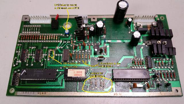
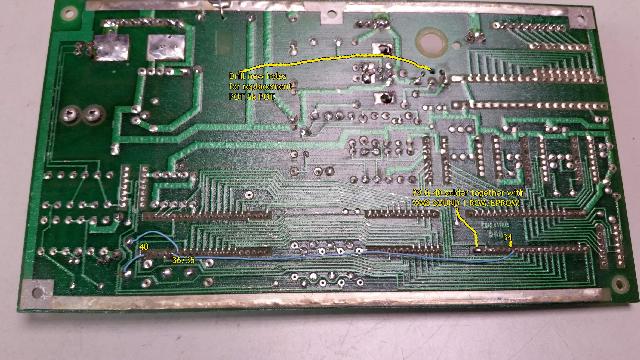
Misc. Sound/Speech Problems and Ideas.
AC Sound Hum in Flash Sound Board.
Flash sound boards seem to hum more than others. To cure this
problem, replace sound board capacitors C10 and C30,
which are in the audio amp circuit.
The grounding of the sound board is important too.
The sound board sits in the lower cabinet and
is screwed into wood, not in the backbox and the backbox
metal grounding panel. Make sure the grounding braid is
connected to ground on the sound board, and the ground
strap is connected between the backbox and lower cabinet.
Flash Background Sound.
Can't get the background sound to work on Flash?
This is a problem with the Green Flipper ROMs and the accompanying
Green Flash game ROM (does not seem to be a problem with the Flash
Yellow Flipper ROM version, but the Green Flipper ROM version is the
'newest' Flash ROM version).
Make sure adjustment #33 is set to 01. Still not
working? Try setting adjustment #31 to 01.
Some General Sound/Speech Tips when It's Not Working.
Here's some general tips to keep in mind when there is
missing sound and/or speech.
- On games with speech (Gorgar, Firepower, Blackout,
Alien Poker, Black Knight, Jungle Lord and Pharoah),
there is a pot on the Speech board which is a fader. It
adjusts the relative volumes of the synth sound and speech.
The overall volume is adjust inside thru the coin
using a separate volumne pot. If a game is not "talking", first
try adjusting the speech board mounted pot. If the speech board pot
is turned "up" all the way, this will give full synth/no speech.
- If there is no sound or speech, be sure to check the fuse(s) on the
sound board first.
- Check the voltages on the sound board. The required voltages on
all system3 to system7 sound boards are +5 volts DC, +12 volts DC and
-12 volts DC. But these voltages are derived right on the sound board,
so the input voltage is 18 volts AC, coming right from the transformer.
There are also test points on the sound board for the DC voltages.
Use a DMM and test these voltages. If any are missing, the sound
board will not work.
- There is a bridge rectifier and a voltage regulator on the
sound board. The bridge rectifier converts AC voltage to DC.
The voltage regulator makes sure +5 volts is really +5 volts!
If +5 volts measure above 5.25 vdc or below 4.75 vdc, either
the voltage rectifier or the bridge rectifier have a problem.
- Check all the connectors on the sound board. Make sure no wires
have broken off.
- Check the speaker(s) in the game. Yes speakers do die, and if the
speaker doesn't work, there won't be any sound! An easy way to test
a speaker (with the game OFF), is to put a 9 volt battery on the speaker
lugs for just a second. The speaker should pull in and make some noise.
- Check the volume pot! Yes these go bad too. Turning it back and
forth, or clean it with some spray contact cleaner. The pot is 5k ohms.
- The amplifier chip on the sound board (TDA-2002) can sometimes get
cracked solder joints. This happens because the amp stands up and has a stand
up heat sink, which likes to get bent over, breaking the amp's solder joints.
Best to resolder the amp on both the component and solder side of the
circuit board to fix this.
- With the game on and in attract mode, press the momentary self-test
button on the sound board. If the sound board makes any sound, this is
a great sign! (You'll need to turn the game off to exit the test mode though.)
Also this sound test will work even if the CPU and driver board are not
installed in the game.
- On system3 to system6 games, go to the solenoid test using the
coin door switches. When the game tests solenoids 9, 10, 11, 12, 13, a different
sound should be heard for each solenoid number (it is helpful to have
the auto-up/manual-down button in the manual-down position, and to
use the Advance buttom to move manually from solenoid to solenoid). If five different and
distinct sounds are not heard, there is a problem! On system7 games,
there is a separate sound test (test number 0), which is right after the
display test.
- On system3 to system6 games, the sound (and speech board, if there is
one) could be fine, but the sound still not work properly. This is
because there are five solenoid driver transistors (Q31, Q33, Q35, Q37, Q39)
on the driver board that trigger the sounds on the sound board. On system7
games, sounds are not triggered by solenoid driver transistors. Instead
there is a separate PIA on the CPU board that does this.
- If the game is Gorgar, Firepower, Blackout,
Alien Poker, Black Knight, Jungle Lord or Pharoah and there is no speech,
make sure the sound board DIP switch is set correctly. Also it's a good
idea to check the sound board jumpers. See the DIP
Switch Setting section of this guide for help with that.
- Intermittent sound problems are usually either bad sound
board sockets (Scanbe!), or bad sound ROMs. If the game has
original ROMs (black, no EPROM "window"), these should be
replaced with new EPROMs. The silver legs on the ROMs can
rot and make bad contact.
- On Black Knight, the sound test button should get the
following sound phrases: "knight, black, defend, challenge, thee,
will, you, i, again, play, cannot, self, enemy, one", and then repeat
until powered off. If that doesn't work,
try removing connector 10J3 on sound board to isolate it from the CPU/Driver
board, then power back on and repeat the sound test.
Note in attract mode Black Knight should say, "you play me,
hahahahaha", every once in a while.
Faint Speech from Type2 Sound Boards.
A reader reported, "While testing the sound/speech board for my
Blackout, I hear all the sounds perfectly. Also all the
speech is there, but is very faint, almost impossible to hear.
Turning the pot on the speech board only varies the volume of the sound
effects, not speech volume.
Is there some sort of mixer on the speech board that could be bad?"
The answer was a bad 1458 sound amplifier at U3 on the sound board.
Reducing Hum on Type1 System3/4 Sound Boards.
As documented by G.Sylvain.
Early type 1 sound board games can have noticeable
hum in the speaker, especially bothersome during
game-over mode. The hum would not be affected
by the position of the volume control on neither
the cabinet nor on the sound board itself.
I made sure all screws on all boards were
present and tight, along with clean brackets,
to ensure a good ground connection.
That did not help.
The second and most obvious problem are old electrolytic
capacitors on the sound board, mainly C10, C30 and C29.
These were replaced with new ones to no avail.
I even replaced the amp's feedback capacitor C13, and again no help.
I noticed that the hum would be greatly
lowered if I reduced the type1 sound board resistor R18 from 220 ohms to 100 ohms.
This resistor controls negative feedback to the TDA 2002 audio
amplifier, thus the overall gain/volume.
On more modern Williams sound boards with speech such as
Black Knight, the hum is almost zero, while the final audio
amplifier circuitry is essentially the same (except for
one additional 1K resistor and a different cap value).
Changing R18 to 100 ohms will reduce the maximum audio
volume of the game, and the volume must be turned up.
I felt that the maximum sound level was still powerful
enough for most home-use applications.
Besides, it lowered the hum enough to make this 'work-around'
fix quite acceptable.
Using a 6802 instead of the 6808/6810 on Type2 Sound boards.
It is possible to install a 6802 processor (instead of a 6808)
and remove the 6810 RAM at IC11 on Type2 sound boards.
To do this, a trace must be cut on the back of
the board below R30. If the trace is not cut,
the pull-up resistor is in place for the processor
swap but the resistor is permanently grounded until the trace is cut.
System9 Sound & Speech Board and System6/7 Games.
The sound & speech boards used in system9 games (Space Shuttle, Sorcerer, Comet)
are essentially the same as the sound & speech board used in system6 and system7.
The system9 sound & speech board are also downward compatible to system6/7 games.
But the advantage
to the system9 speech board is it can be jumpered to use either 2532 or 2732 EPROMs
(the system6/7 speech board can not be easily converted to use 2732 EPROMs).
The system9 version has jumpers to select the EPROM type
(the jumpers are documented in the system9 schematics).
C-8224 is the sound board, and is the same for system6/7 and system9.
C-8228 is the speech board used in System6/7 games.
C-10716 is the speech board used in system9 games.
3j. When Things Don't Work: Flipper/Drop Target Problems & Upgrades
Flipper Introduction.
Flippers connect the player to the pinball
game. Having perfectly working flippers is extremely important. Here
are some common flipper problems and answers. Much of the
older system3 flipper information is courtesy of David Gersic.
During the system3 to system7 era, three different styles of
flipper mechanisms were used. First was the EM (electro-mechanical)
style of flippers. These were used on the first system3/4 games
(Hot Tip to about Stellar Wars).
There are separate parts for the solenoid mounting, playfield bushing,
and crank stop. Since these parts are not
attached to each other, just screwed to the wood, this leads to a
sloppier feeling flipper. But short of replacing the mechanism with
modern parts, there isn't much that can be done about that.
In short, these flippers are not
very "snappy", but can be modified for better performance.
A first generation flipper on a World Cup. Note all the parts are separate,
and not tied together on a flipper base plate. Picture by D.Gersic.
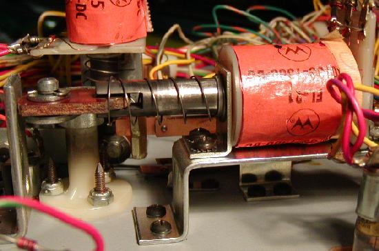
|
The second generation of flipper started with System6 (Tri-Zone) but
really showed up during production of Firepower. This means that
Tri-Zone, Time Warp, Laser Ball and Gorgar usually have the
old style system3/4 flippers. The second generation flipper style
was an improved mechanism over the first
generation flippers, with all the flipper parts tied together on a
flipper base plate, and used a better style flipper pawl (crank) to
hold the flipper bat shaft in place.
This second generation style flipper mechanism was a big improvement over
the old for the performance and feel of the flippers, but a big step
backwards in serviceability. A common wear part, the coil stop, cannot
be replaced. When it wears out (and in a game this old it's already
worn out!), the entire mechanism must be replaced. This was unlike the
first generation flippers that has replacable coil stops.
The second generation style flippers was used into the system7 and
seemed to end around Firepower II (with Laser Cue and Star light having
the third generation of flippers). For example all Black Knights
have the second generation style flippers.
A second generation flipper on a Firepower. Note the non-replacable coil stop,
and all the flipper parts are now mounted on a metal base plate.
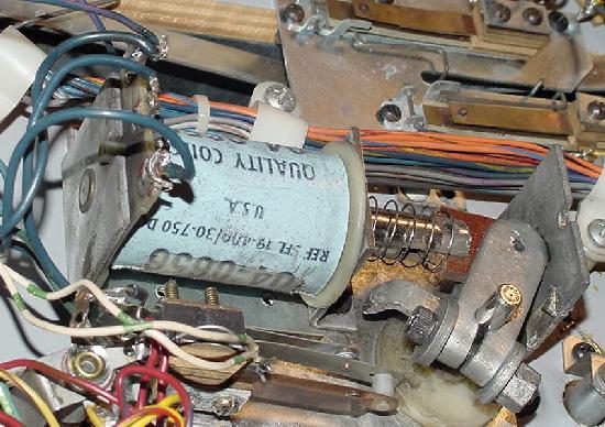
|
The last style, the third generation flippers,
were implemented during the production of Firepower II (the end of
the System7 era). These are basically the same flipper mechanism that was used
by Williams up to about 1992, with a replacable coil stop and an improved
coil plunger/link and improved flipper pawl (crank). This is
by far the most robust, most easily serviced, and best feeling flipper
system Williams used in this era of Williams games.
A second generation flipper base plate with a non-replacable coil stop.
Picture by D.Gersic.
|
The first, second and even third generation of flipper mechanisms can all
be replaced with the newer 1990s WPC mechs. This will make the flippers feel far
better, perform better, last longer, and parts are readily available.
Unfortunately to do this on first and second generation flippers,
almost the entire mechanisms needs to be replaced.
This includes the baseplate, the plunger/link, the nylon flipper bushing, the
flipper bat, the coil stop, and other parts.
Remember, all system3 to system7 flippers will have
EOS (end of stroke) switches. This tells the game a flipper is
at full extension, and to turn off the flipper high power. If
this switch is broken, it will cause big problems. For example,
a weak flipper or a flipper coil that burns up are two typical
EOS switch related flipper problems.
Bad EOS switches should always be fixed. Most flipper problems
in these games are related to bad or poorly adjusted EOS switches!
Also all system3-7 games will have a diode attached at the flipper
coil. Make sure the diode is oriented correctly. See the picture below:
The right flipper coil on a Firepower. The top flipper lug has the 1N4004 diode's
NON-banded lead and the EOS switch and the ground wire going to the driver board's
flipper relay. The middle lug has the other EOS switch wire. And the bottom lug has
the banded lead of the diode and the power wire. Note the high-power EOS switch
and the low-voltage switch matrxix for the lane change option. Note this is a
"2nd Generation" style flipper with the non-replacable coil stop.
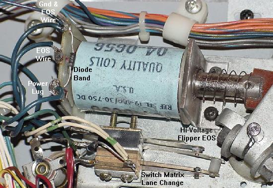
|
How Flippers Work.
Flipper coils are actually two coils in one package.
The "high power" side is a few turns of thick gauge
wire. This provides low resistance, and therefore
high power. The "low power", high resistance side is many turns of much
thinner wire. This side of the coil is important if
the player holds the cabinet switch in, keeping the
flipper coil energized. The high power low resistance side of the
coil is only active when the flipper is at rest. But when the flipper is
energized and at full extension, the low powered side
of the flipper coil is used so the coil doesn't get hot and burn.
All system3 to system7 game used a series wound flipper coil. The common
lug (where both the low and high powered coil wires were
connected together) on these flipper coils
was the middle of the three lugs. Also these
coils used ONE diode across the two outside lugs. The EOS
switch on these games, when opened, enabled BOTH the high
power and low powered coils together. This style of flipper
coil did NOT use a 2.2 mfd anti-spark EOS capacitor. The problem
with this series wound coil was the "back spike" of current
that occured when the EOS switch was opened. This cause the
EOS switch to excessively wear and pit.
With the introduction of F-14 Tomcat in 1987, Williams changed to
the parallel wound style flipper coil. This coil now used an
outside lug as the common lug (where both the low and high
powered coil wires were connected together). Also TWO diodes
were used and required on these flipper coils. This parallel
wound coil eliminated the "back spike" of current when the EOS
switch opened. It also allowed the use of a 2.2 mfd 250 volt capacitor
to further limit EOS switch sparking and pitting.
Now when the EOS switch opens,
this removed the high powered side of the
coil from the circuit. The low powered side of the flipper
coil is always in the circuit, but is essentially ignored
when the high powered side is in the circuit. This happens
because the current takes the easiest path to ground
(the low resistance, high power side of the coil).
The low power high resistance side of the
flipper coil won't get hot if the player holds the
flipper button in. Note adding the spark surpressing EOS switch
capacitor to a series wound flipper coil has no effect! (For the
capacitor to work, a parallel wound flipper coil is needed.)
Unfortunately parallel wound flipper coils can not be easily
adapted to system3 to system7 games (except Firepower2 and later).
Prior to Firepower2, all system3 to system7 games had 28 volt
flippers. With Firepower2 (the third from last system7 game),
Williams changed to a 50 volt flipper. All Williams parallel wound
flipper coils are designed for 50 volts and not 28 volts. Therefore
adapting the 50 volt parallel wound flipper coils to the system3 to
system7 games with 28 volt flippers is not recommended. But if you
want to try, it certainly is possible.
When converting a older 28 volt series wound flipper coil to a newer
parallel wound coil, you must match
the correct resistance parallel flipper coil to the game.
To do this, measure the resistance of the high power side (low resistance side)
of the stock series wound flipper coil.
Then measure the resistance of a new parallel wound flipper coil,
and get a coil with the same resistance. Note the "hold" side of the
coil (the higher resistance side, around 125 ohms) is not necessary to match - it's
the power side (low resistance side, around 4 ohms) that needs to be matched.
The Driver Board Flipper Relay.
The flippers are only enabled during game play and in
diagnostic/audit mode. The flipper enable relay is what turns
the ground off and on connected to the flipper coils.
The flipper enable relay is located on the Driver board, and it's
a 6 volt relay (though it is driven by logic 5 volts.)
When entering diagnostic mode (any test after the score display test),
the flipper relay should click on (activating the flipper
buttons). Also audit mode will immediately turn on the flipper relay
(which is weird if the batteries are dead and game boots to audit mode.)
This relay connects through transistor Q13 (2N4401) and a 7402 at IC8
and a 7402 at IC9 and a 7408 at IC7, and ultimately the 6821 PIA at IC5. If any of these
components are bad, the relay may not activate the flippers. First test transistor
Q13, as this fails the most often.
A replacement 6 volt flipper relay is available from Mouser,
part# 528-7810-1 (MagneCraft #W78CSX-1, $5.50).
Flipper relay with the cover removed. You can see that
battery corrosion has taken a toll on this relay. The tiny
winding is broken too (blue arrow), so this relay will not energize.
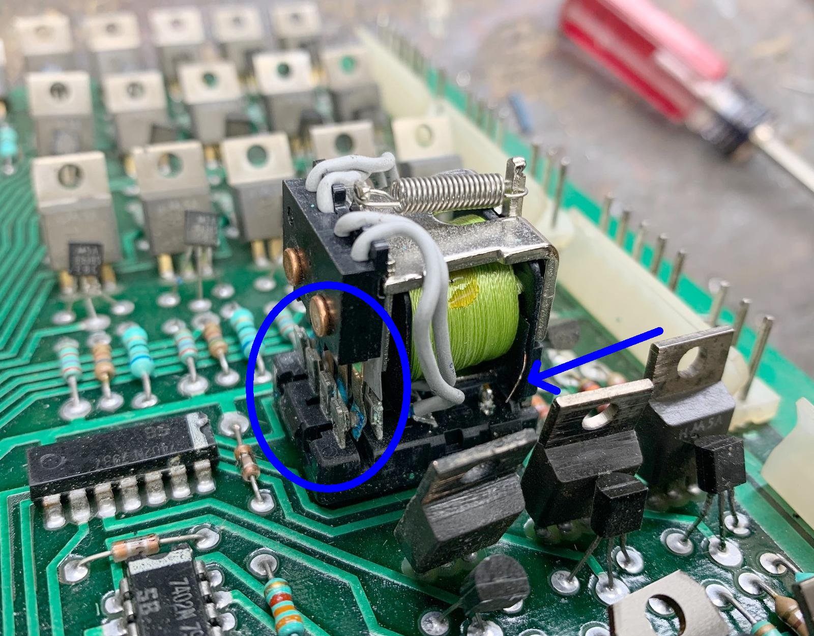
|
Battery corrosion loves to wreck the flipper relay. Since the batteries are
directly above the flipper relay, the outgassing of the batteries often
harms the flipper relay. The only way to really examine the flipper relay
is to remove it's cover. This generally isn't too difficult, there are plastic
tabs on the side which allow the cover to be removed. Also you can check the
resistance of the flipper relay coil (while it's mounted to the driver board.)
It should read about 40 ohms. If you get some number different, it could be
that battery corrosion has broken a winding on the flipper relay.
"Lane Change" Switch Shorts to the EOS Switch.
Firepower was the first pinball game to use "lane change". This feature
allowed the player to move the lit lamps on the top lanes (above
the pop bumpers), where the
ball feeds from the shooter lane. The lit lamp movement is done with the right
flipper cabinet button (later games used both the right and left flipper
buttons). This is a standard feature on pinballs today, allowing the
user to complete these lane lights easier for increased bonus multipliers,
and to make "skill shots"
on many games (Medieval Madness and Monster Bash come to mind).
The right flipper high-power EOS switch and the low-voltage
switch matrxix lane change switch, doubled up on the same
switch stack. Notice the nylon switch activator, which isolates
the EOS switch from the lane change switch. Also note the
1N4004 diode on the lane change switch wires.
|
Until system11, Williams "doubled up" the EOS and lane change switches
on the same switch stack, and insulated the two switches from each
other (the lane change switch was doubled up with the flipper EOS switch
because it was an
easy way to close a switch when a flipper button was pressed).
The insulation was used because the flipper EOS switch was high voltage at
28 volts (and later 50 volts), and the switch matrix lane change
switch was a low voltage 5 volt switch. If these two switches shorted
together, the driver board's switch matrix circuit (including IC15-IC18
and the switch matrix PIA at IC11) would fry, making the entire game
unusable. This was a very common problem when someone was working
on the flipper EOS switches with the game power on!
The moral of the story is this: Never work on a flipper EOS switch
when the game's power is on!
Flipper Diagnostics.
If the flipper(s) don't work at all...
- Check the flipper fuse. On games Flash and later, this is power
supply fuse F4. On games before Flash, there is a flipper fuse under the playfield.
- Clean the flipper cabinet switch contacts and the
EOS switch contacts with a small metal file. Make sure this normally closed
EOS switch is adjusted properly with a 1/8" gap at full flipper extention.
- Check for 28 to 35 volts DC (or 50 to 70 volts DC on Firepower2 and later)
at the flipper coil. Put a DMM on DC volts,
and the black lead on ground (metal side rail of game). Put the red
lead on any of the three lugs of the coil. It should be between
28 and 70 volts on any of the three flipper coil lugs.
If just one or two of the flipper coil lugs have
voltage, than the flipper coil is broken.
No voltage on any lug means a fuse is blown, or the main power wire leading
to the flipper coil has broken. Note on late System7 games
(Firepower2 and later), there is a separate 50 volt power supply for the flippers.
- Test the flipper coil itself. To do this, turn your game on and
leave it in attract mode. Attach an alligator test lead to
ground (metal side rail of game), and momentarily touch the other
end of the test lead to the middle lead of the flipper coil. The coil
should activate. Now momentarily touch the ground lead to the outside flipper coil
lug which attaches to the EOS switch. Again the coil should fire. Note do
not touch the ground lead to the outside flipper coil lug which brings
the main power to the flipper coil, or the flipper fuse will immediately blow.
- If there is no power at the flipper coils, but the power supply fuse F4
is good (or playfield fuse, games Flash and earlier), look at the power
supply connector 3J3 pins 4,5 (bottom lower left). This supplies power to the flippers.
- If there is power at all the flipper coil lugs but the flippers
still don't work, check the EOS switch is closed (and clean)
when the flipper is at rest and there are no broken wires on the EOS switch.
- If there is power at the flipper coil lugs and the EOS switch checks out fine,
check the ground return to the flipper cabinet buttons. With the game in attract
mode and a flipper cabinet button pressed, use an aligator test lead
and ground either flipper cabinet switch lug. This should fire the flipper.
If it does not, there is a break in the wiring between the playfield and
the flipper cabinet button. If only one lug fires the coil, the flipper
cabinet switch is dirty or bad.
- Check the wiring harness connector that separates the backbox from the cabinet.
Find the medium sized white connector with the thick orange wires and
re-seat this connector. If the flipper(s) work now, the connector pins
should be replaced in this connector.
- If there is power at all flipper coil lugs and
the EOS and flipper cabinet button switches check out:
Now check the driver board connector 2J12 pins 1,2 (second connector
from the top on the left side of the driver board). This brings
the orange ground wires (the flippers are the two lower-most
pins 1&2 on 2J12) to the driver board, which then goes through
the flipper relay (mounted on the driver board). Perhaps
the connector or male header pins on the driver board
need resoldered or re-crimped. If these are Ok, then
the problem is either a crack driver board trace, a cracked connector pin
at 2J12 pins 1/2, the flipper relay itself,
or the flipper relay's driver transistor. Note if one flipper works and one
doesn't, the driver transistor is fine, and the problem is likely the 2J12
pins 1,2 connector.
- Also check the flipper coil with a DMM set to
ohms. With the game turned off, try this:
- Notice the three solder lugs for the flipper coil.
The center lug has both the thick and thin wires connecting to it.
This is the "common" lead.
- Put one lead of the DMM on the center common flipper lug.
- Put the other lead of the DMM on the thick wire lug.
Around 3 ohms should be seen. This is the high powered side of the coil.
- Put the leads of the DMM on the thin wire lug of the coil.
About 3 ohms should be seen until
the flipper is manually moved to the full extended position, opening
the EOS switch. Now about 125 ohms should be seen. Note if more
than about 5 ohms is seen when the flipper is at rest in this test, the EOS
switch is pitted and causing some resistance. Clean it for stronger
flippers.
- If the above readings are not seen, the flipper coil is bad.
Typically the hold side of the coil goes bad more often that the power side.
- Test the flipper diode(s). To do this you'll have to cut one lead
of each diode off the coil lug. Then set the DMM to the diode setting.
Put the black lead of the DMM on the banded side of the diode. About
.4 to .6 volts should be seen. Reverse the leads and no reading should be seen.
When done, re-attach each diode lead (or just put a new diode on!)
- The driver board flipper relay is not engaging. If the relay that turns the
ground on to the flippers (when a game starts) has failed, the flippers will never work.
Replace this relay or examine the logic that controls this relay.
This relay connects through transistor Q13 (2N4401) and a 7402 at IC8
and a 7402 at IC9 and a 7408 at IC7, and ultimately the 6821 PIA at IC5. If any of these
components are bad, the relay may not activate the flippers. First test transistor
Q13, as this fails the most often.
If the flipper works, but "Flutters".
- When activated, doesn't hold up (the flipper "flutters"). This often means
the hold winding on the coil itself is broken. The hold winding on the coil is the thin
wire. If it is broken, you can usually see the wire has broken away
from one of the solder lugs (the middle lug should have both the
thick and thin wire attached to it). Test the coil (see above) with a DMM.
Sometimes the break can provide an intermittent connection.
- Another problem could be the EOS switch is not adjusted properly.
If the moving EOS switch blade does not have enough tension against the other
switch blade, flipper flutter can occur. Sometimes adjusting the EOS switch
with the game on and the flipper button held in is the best way (but be careful
not to short the high voltage EOS to a low voltage lane change switch!), because
wear in the flipper linkages can give wrong EOS switch measurements when moving a flipper
bat by hand.
- Also check the cabinet switches for proper tension and that they are clean.
- Lastly, try replacing the coil stop. A very worn coil stop can cause flipper flutter.
If one or both flippers are weak...
- Rebuild the flippers. Play and wear in the flipper
parts is the primary reason for weak flippers. A mushroomed flipper
plunger dragging against the coil sleeve is a classic cause of weak
flippers.
- Make sure there is about 1/16" up and down play on the flipper paddle.
To test this, from the top of the playfield, grab the plastic flipper and
pull up. There should be some play. If not, the flipper could be binding
on the nylon playfield insert. This gap is adjustable from under the
playfield by changing the flipper pawl's grip on the flipper shaft.
- Clean the EOS switch contacts and the
cabinet flipper switches. These are high-voltage tungsten switch contacts,
and a metal file is needed to clean them. These switch contacts often
become pitted and tarnished, and resistance develops.
- Clean or replace the cabinet flipper button switches. These switch contacts
often become pitted, and resistance develops.
- Check the backbox mounted
bridge recitifer that supplies voltage for the flipper
coils. An open diode in the bridge
rectifier that supplies power to the flippers can cause weak flippers.
A fatigued or cracked solder joint or solder lug on this bridge
can do that too. This is rare, but does happen. This problem will
affect BOTH flippers equally.
Flipper coil gets very hot...
- Check the EOS switch to make sure
it is adjusted properly (1/8" gap at full flipper extension),
and that the contacts are clean and filed. If the coil is getting
hot, this means the EOS switch is not opening.
- Check if the "hold" winding is broken on the coil.
The hold winding is the thin flipper coil winding.
A flipper gets stuck in the up position...
- Check the EOS switches and the flipper pawl. Often the
rubber coating on the flipper pawl that contacts the EOS
switch will wear. This causes the flipper pawl to hang up
on the end of the EOS switch. The end of the EOS switch
can even get torn and fray from this.
- Flipper is too tight inside the playfield flipper bushing. This causes
binding between the playfield bushing and the flipper crank assembly. There should be
about a 1/32" gap. If the flipper paddle doesn't have any vertical movement,
it's too tight.
- Check the flipper return spring. Is it broken or missing?
- Check the flipper cabinet switches. Are the switch contacts fused together?
If so, try and separate and then use a metal file and file the switch
contacts smooth (or just replace the switch contacts/blades!)
Improving the First Generation System3/4 Flipper Design.
The flippers used to about Flash, and was basically a
hold over from the EM era. These flippers are not robust enough to hold up
to the quickness of the newer solidstate games. But they can be
improved with these steps, as suggested by David Gersic:
- Rebuild the flipper assembly with fresh parts. This includes
the coil stops, plunger and links, coil sleeves, EOS switches, and pawls (if needed).
Pinball Resource has all these parts.
- Replace the cabinet switches. Loss in current can result from pitted (high resistance)
flipper cabinet switches.
- If these two things above are done, this leaves a functional but
'clunky' flipper. The flipper coils are plenty strong, but the flipper paddle (bat)
is too heavy. Flipper action can be greatly improved if the bat is
made lighter. A lighter flipper bat needs less energy
to put the flipper into motion, making the flipper more responsive and snappier.
- Lighten the original flipper bat to
about 1 ounce, compared to 1.5 ounces for the original unmodified
flipper bat (this 1/2 ounce makes a *big* difference!)
Because the flippers will have less rotating mass, they will be more "snappy".
To lighten the original first generation Williams
flipper bat, first remove the plastic shoe from
the bat (there is a single screw underneath the bat).
Then screw the metal bat to a junk piece of wood, and drill
the metal bat baseplate to remove metal. This makes
the whole bat about 1/2 ounce lighter. Drill a large hole near the shaft, and
progressively move to a smaller drill hole size as the holes move
out to the tip. A total of seven holes can be drilled: 5/16", 5/16", 1/4",
7/32", 3/16", 5/32", 1/8".
Doing the above steps will give very nice flipper action on
these first generation flippers.
Reinstalling the newly drilled flipper bats on the game,
the flippers do indeed feel more "snappy" and responsive,
they no longer bounce back when they reach the end of stroke.
For a total investment of $0 (assuming a drill is already owned!),
better flippers on early Williams solid state games are possible.
A system3 flipper bat being drilled to reduce its weight, and
to increase its performance. Picture by D.Gersic
|
A drilled out system3 flipper bat with seven holes, sizes 5/16", 5/16",
1/4", 7/32", 3/16", 5/32", 1/8". Picture by D.Gersic
|
New Style Flipper Bats on First Generation Flippers.
The first generation system 3/4 style
flipper mechanisms uses pointed setscrews to
secure the pawl (crank) to the flipper shaft. The second generation and later mechanisms
use a clamping bolt on the crank. The difference is important, as the
older style flipper shaft has a recessed area for the setscrew to make
a "divot", as the setscrew point is driven into the shaft. The newer style
flipper shaft is smooth and lacks this recess. If a new, smooth shaft flipper bat
is used on an old set screw pawl mechanism, the resulting "divot" will be pushed out,
permanently wedging the crank and shaft together.
Top: Old style system3 first generation flipper bat
with recessed shaft and metal base plate.
Bottom: New style smooth shaft flipper bat.
Pictures by D.Gersic
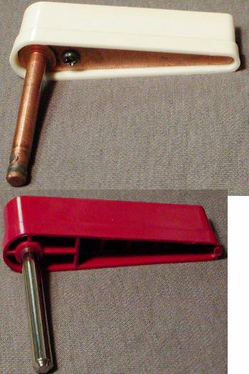
|
Rebuilding System6-System7 Second Generation Flippers.
Recently some parts have become available from
Pinball Life that
allow easy and proper rebuilds of the system6/7 second
generation flippers (from Firepower to FirepowerII).
Here are the parts needed:
- Flipper Rebuild Kit: "sys_6_&_7_rebuild" from Pinball Life.
These are all the parts needed to rebuild a pair of flippers.
Skip the rest of the parts listed below if buying this kit.
- Complete Flipper Assembly: C-8230-L (left) and C-8230-R (right)
from Pinball Life.
This is the complete assembly including the baseplate and
the flipper coil/EOS switch. Again skip the rest of the parts
listed below if buying this.
- Plunger/Link/Pawl assembly: B-10655-L (left) and B-10655-R (right)
from Pinball Life. Often the WPC flipper parts A-15848-L or A-15848-R
are used (incorrect for the original second gen flippers).
- Coil Sleeve: 03-7066-5 (2 3/16" long). Often the WPC flipper part
is used (2 1/4" long), which is 1/16" too long.
- Coil support bracket: 01-6928 (NLA) or 01-7695-1.
Often the WPC bracket 01-7695 (with the four "ears") is incorrectly used.
- Nylon playfield bushing: original part 03-7568 should be used.
Often the WPC bushing 545-5070-00 (with a recessed extension) is incorrectly used.
- Flipper return spring: 10-135 or 10-376 (consistent width).
Often the WPC conical shaped 10-7 or 10-376 spring is incorrectly used.
- EOS switch: original part SW-10A-50 or Sys_6_&_7_EOS (Pinball Life)
should be used. Often the WPC EOS switch 03-7811 (too long) is incorrectly used.
- Flipper Coil: SFL-19-400/30-750 (Pinball Life) or SFL-23-600/30-2600 (Pinball
Life). Which coil to use depends on the game.
- Flipper base plates: C-8231-L (left) and C-8231-R (right) from Pinball Life
only. Nobody else seems to sell these.
Upgrading System3-System7 Flippers to New Style WPC Flippers.
Another method of improving the first and second generation of Williams
flippers involved just retrofitting new style flipper parts as used
on late system7 (Laser Cue and Star Light), System9, System11, and
WPC up to Terminator2. This
completely replaces the old flipper assembly with a modern design.
This will make the flippers feel far
better, perform better, last longer, and parts are readily available.
Unfortunately to do this, almost the entire mechanisms needs to be replaced
with the newer C-13174-L and C-13174-R parts.
This includes the baseplate, the plunger/link, the nylon flipper bushing,
the pawl (crank), the flipper bat, the coil stop and other parts (sometimes
including the flipper coil itself).
Here are the parts used to convert a system3-7 game
to the newer WPC era flippers. Also a WPC non-fliptronics flipper
rebuild kit A-13524-1 can be bought which includes many of
these parts (has EOS switch, plunger/link/pawls, coil stops, coil sleeve,
springs and screws, but does not include the baseplates).
Also complete flipper assemblies C-13174-L/R may be purchased.
Thanks to S.Shabow for some of these part numbers.
- Flipper Baseplates: B-13104-R, B-13104-L (right and left)
- Nylon Flipper Bushing: 03-7568, one for each flipper
(uses three 6-32 x 3/8" bolts and nuts).
- EOS Switch Bracket: 01-9375 (one for each flipper)
- Return springs: 10-376 conical (this is the plunger style).
Or 10-364 non-plunger style (highly recommended, but it's
not the original design).
- Coil stop: A-12111 (uses two allen head 10-32 x 3/8" bolts),
one for each flipper. Often A-12390 is incorrectly used.
- WPC Plunger/link/Pawl assembly:
B-10655-L (left) and B-10655-R (right).
The parts A-15848-L (left) and A-15848-R (right)
are often used, but this style has the wrong link
for a conical plunger return spring. So get the
correct link depending on which flipper return spring you
are using. Personally I recommend a non-plunger style return
spring as it is far more robust.
The flipper pawl only (no plunger/link)
is part number A-17050-L (left), or A-17050-R. The plunger/link
alone is part number A-15847 (non-conical spring type),
but you will also need the flipper link Spacing Bushing 02-4676.
- Coil Sleeve: 03-7066-5, 2 3/16" long (one for each flipper).
- Flipper EOS switch: 03-7811. Don't try and use the
SW-1A-194 EOS switch.
- Flipper Coil Bracket: 01-7695 or 01-7695-1. This is the style
with the four retaining clips for a conical return spring. You can
use the older 01-7695-1 bracket if you are using a non-plunger style
return spring.
- Flipper Bats: the originals can usually be used, but it is suggested to get new
WPC bats 20-10110-6 (yellow) or 20-10110-5 (white).
- Flipper Coil: the original flipper coil can sometimes be retained, depending
on the game. Machines with
first generation flippers use a smaller flipper coil that is shorter than a WPC
flipper coil. This short flipper coil must be replaced with the longer
SFL-19-300-750 coil (as used on Firepower) or SFL-19-400/30-750 coil (slightly
weaker by plenty strong enough), or a System 11 style coil, or similar power
WPC coil like FL-11630 (which should be the equivalent to the old coil). Or
if you like to do a direct comparison:
- Note if replacing the original small flipper coil with a newer longer coil
that fits the WPC flipper mechs,
make sure to use a similar power coil. The best way to do this is to measure the
resistance of the original flipper coil and compare it to the chart of WPC
flipper coils below (but for the most part, a FL-11630 should be equivalent).
- Using a DMM, put the middle DMM lead
on the center lug of the flipper coil. Put the other DMM lead on either outside
flipper coil lug. Note the resistance.
- Move the outside DMM lead to the other
outside lug. Again note the resistance, which should be quite a bit different.
- The resistance number that matters is the lowest
resistance of the two measured values (in the 3 to 6 ohm range).
This represents the high-powered side of the flipper coil.
- The high resistance number (in the 90 to 150 ohm range) is the hold (low-power)
side of the flipper coil, and does not need to be matched.
- Find a correct physical sized flipper coil with the same or similar
low resistance reading.
- Remember a 3 ohm flipper coil is stronger than a 3.5 ohm (or 4 ohm) flipper
coil. Though a half ohm doesn't seem like much, it does make a big difference
in the power of the flipper! To give an idea of the power differnce, look
at the the half ohm as a percentage of the total ohms (more than 10 percent!),
and this should give an idea how much power increase just half an ohm can
make in flipper coil power.
- Flippers only need to be strong enough to make top-of-the-playfield shots.
Don't make your flippers too strong, or you will break playfield plastics and
rip up playfield posts!
- Don't forget to replace the EOS and cabinet flipper button switches. These become
pitted (high resistance) and can reduce current flow.
Some games use a double-stacked EOS switch to control lower and upper
flippers (the second switch mounted on the EOS closes, which activates the
upper flipper). In this case the original EOS switch stack needs to be disassembled
and the EOS switch used on the inside of the switch bracket,
and the upper flipper switch set on the outside of the bracket.
It fits fine this way with a very small bend of the switch.
When installing a WPC era flipper coil with *two* diodes instead of one diode,
the wiring orientation is exactly the same. Even though the 'common' lug of
the coil is different, the wires go on the same relative lugs. Best to
remove the wires from the old coil and transplant them
to the new coil one at a time. If you mix up the wires, the flipper fuse
will most definately blow and the coil's diodes will short.
The baseplates mount in the same footprint as the originals.
Sometimes you have to reroute the wiring slightly because of how
all the parts line up. Also sometimes it may be necessary to
twist the entire flipper base plate to a slightly different
orientation to avoid the wiring harnesses and GI. Also maybe a GI lamp will
need to be repositioned slightly.
If using the original baseplate playfield holes,
fill in the old screw holes
for the baseplate with a toothpick and some white glue to give the baseplate
screws a good bite in the playfield. After these parts are installed,
the improvement in game play is quite dramatic.
EOS switch Note.
Many newer WPC style games use a normally OPEN end-of-stroke (EOS)
flipper switch. If you are using WPC flipper assemblies from one of these games,
the EOS switch must be flipped-over and adjusted (bent) to be a normally CLOSED
switch for a system3 to system7 games. It is extremely important
that the EOS switch be adjusted correctly on your system3-7 game! If the EOS
switch is mis-adjusted, the flipper coils can burn. Remember when the flipper is fully
energized, the system3-7 EOS switch contacts should be open 1/16" to 1/8". When
the flipper is at rest, the EOS switch contacts should be closed (touching).
Also remember that many WPC games use an EOS switch that is unsuitable for
a System3-7 game. If the WPC EOS switch has small gold contacts, you can NOT
use this EOS switch in a system3-7 game (the EOS switch will burn up!) Typically
if you had to flip-over the WPC EOS switch to make it normally closed, chances
are good this is not the correct EOS switch for a system3-7 game. The proper
WPC EOS switch should have large silver Tungston contacts, designed for the
non-Fliptronics WPC games (prior to Addams Family).
WPC Flipper Coil Numbers and Strength.
Resistance is included below.
The flipper coils are listed below from weakest to strongest.
The first resistance number is the power side of the coil, and
the second number is the hold side of the coil.
- FL-11753: used for small flippers, like the "Thing" flipper on
Addam's Family. 9.8 ohms/165 ohms. Usually a yellow coil wrapper.
- FL-11722: used for weak flippers, like Twilight Zone's upper
right flipper. 6.2 ohms/160 ohms. Usually a green coil wrapper.
- FL-11630: "standard" flipper strength, as used on older games
like Earthshaker, Whirlwind, etc. 4.7 ohms/160 ohms. Usually a red coil wrapper.
- FL-15411 : strong flipper, as used for main flippers on Addam's Family,
Twilight Zone, etc. 4.2 ohms/145 ohms. Usually an orange coil wrapper.
- FL-11629: strongest Williams flipper. Used on most of the newest WPC
games. 4.0 ohms/132 ohms. Usually a blue coil wrapper.
Drop Targets on System3 to System6.
The older System3 to System6 drop targets are problematic. They use *two*
switches per target, unlike newer games that only use one switch.
One of the switches closes momentarily when target drops,
thus giving the score. The other switch closes when the drop
target is down, and stays closed as long as the target stays down.
Because of this two switch per target system, older drop targets
can *not* be replaced with newer and more robust drop targets banks.
The new style, less problematic drop targets with a single switch were
used starting with System7 and Black Knight.
The "down" switches of the drop targets in a bank are all connected
together in series, daisy chained from one target to the next.
When all targets are down, the circuit is completed
and tells the CPU/Driver board to reset the drop target bank.
If there's a bad switch on one or more of the drop targets in the bank
or the daisy chain is broken, the game does not know all the targets are
down.
Testing a System3-System6 Drop Target Bank.
To see if a bank of drop targets are working properly,
first put all the drop targets into the reset (up) position.
Then put the game into the switch test mode.
Now drop each target in a bank one by one. In System3 to System6 games,
each drop target has two sets of contacts. One is a momentary
contact that is only engaged while the target is dropping, and the second is
a continuous contact that is wired in series with the targets.
So in effect, there is a "last series" switch that is closed when all the
targets in a bank are down (this is what would
trigger a drop target bank reset in game mode).
When going through switch test, each target's
switch numbers comes up once when a target is dropped. After all the
targets are down in the bank, the
last "series" switch number should come up in the switch test.
Its possible that the drop targets are wired incorrectly too. This
would cause the last "series"
switch to never close when all of the targets are down.
A three bank drop target as seen under the playfield. Note
the three circuit boards, one for each target.
Picture by D.Gersic
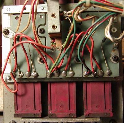
|
System3-6 Drop Target Parts & Rebuilds.
Remove the circuit board from the backside of the drop target bank
(two screws; there is one circuit board for each drop target!)
A horseshoe shaped spring brass wiper is attached to the back of each drop target.
The horshoe wiper contact points are for scoring and letting the game know that
all of the targets in a bank are down. Non-scoring targets, or target
banks that do not reset are likely to be traced to dirty contact
points on these wipers, or on the small circuit board that they rub on.
The two horseshoe contact points that must be cleaned and then lightly lubricated.
(Williams issued a service bulletin dated June of 1980 where
recommend lubricating the targets to ensure proper operation).
A good lubrication is the clear Teflon grease that Radio Shack sells.
Sometimes the circuit board plating
that the horseshoe wiper contacts ride wears out, making the circuit
board useless. To prevent this, lubricate the contact area
with a VERY LITTLE amount of the Radio Shack clear Teflon grease.
Check that the contact points on the horseshoe
are OK, as they sometimes fall off or
the wiper breaks. This results in a sharp edge that can scrape the copper
trace right off of the circuit board.
The circuit board must have enough tension on
the horseshoe wiper to make reliable contact.
If the tension is too stiff, then the target will not move freely.
Daina explains if the horseshoe contact itself is bad or missing,
an old Williams score reel horseshoe contact can be used.
The score reel version is a mirror image of the
drop target horseshoe, but this really does not matter.
They can be turned around and the contact points
polished and bent. It's not a perfect solution, but it works in a pinch
(the electronic drop targets want gold-plated contact points,
which the EM horseshoe contacts will not have).
So with a little bending and polishing they can be used.
The "horseshoe" shaped wiper contact,
attached to the drop target. Do not over
tighten those two screws!
Picture by D.Gersic
|
The circuit board
is the other half of the assembly. As the points on the horseshoe wiper move
from the top of the board to the bottom, a circuit is completed,
then broken, to let the game know that the target has dropped. Then
another circuit is completed when the target is all the way down.
This second circuit is daisy chained across the entire bank, so any
one target that is not working perfectly can cause the whole bank
not to work right, as the game can not determine that all the targets
are knocked down.
A single drop target's circuit board. The copper plating
can wear right off the board!
Picture by D.Gersic
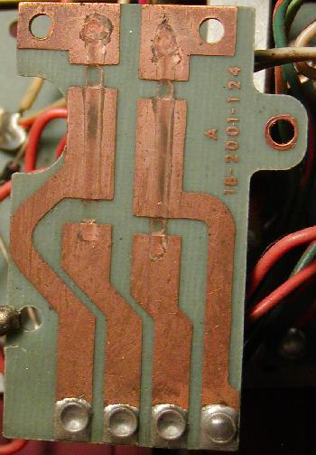
|
There are additional problems in this design that can cause
non-dropping targets, as David Gersic explains. When reassembling
the target bank, the little screws that hold the plastic rails to the
metal body and that hold the wiper circuit board to the plastic rails can be
over-tightened. This crushes the plastic rail just enough to drag on the
targets and keep them from failing. If the drag is not too bad, the
screws can be loosen. Or a shim of plastic can be fitted to give the
targets more moving room.
The target circuit board, and the white plastic rails for a target. Do not over-
tighten the circuit board screws, or this can deform the rails, stopping the
target from falling.
Picture by D.Gersic
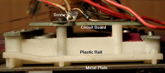
|
More problems in drop target banks are the switch diodes vibrating themselves
loose. If this happens, the drop targets stop scoring. Use short leads
on diodes and mount it with heat
glue gun or silicone rubber compound. Some games have small capacitors on
bumper and drop target switches. Again, mount these with short leads and
silicon to dampen the vibration.
Another angle of the target circuit board removed from a drop target assembly.
This is from a system6 Blackout. Notice the slight difference in the circuit
board compared to an earlier system3 version shown above. This modification
on the "open" part of the board (blue arrow) minimizes stress on the horseshoe
contacts.
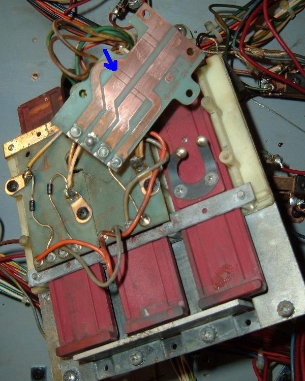
|
Lastly, make sure the "jumper wires" (daisy chain) to each circuit
board on the back are present, and have a good
solder connection. These are sometimes break,
or are completely missing.
These old target banks are tricky to adjust, and require quite
frequent maintenance. When properly cleaned and adjusted, the bank
will work in home-use without troubles for about six months to a year.
But a periodic cleaning of these drop targets will be required,
even in home use. These drop targets are not maintainence free!
System7 drop targets used leaf switches
instead of horseshoe switches.
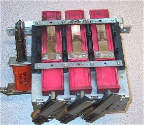
|
System9 drop targets used micro switches
instead of leaf or horseshoe switches.
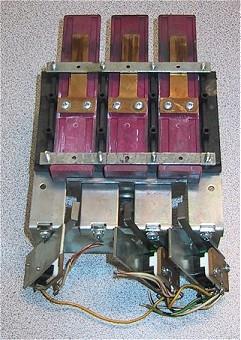
|
3k. When Things Don't Work: Miscellaneous Oddities
Problem: I installed two LEDs in my System7 CPU board. But
the diagnostics appear to be backwards.
Answer: tracing out how the LEDs are driven, it looks like they Williams
goofed and got them backwards. LED1 on the System6 board becomes LED2 on
the System7 board, and vice versa. So when the top LED on a system7
CPU board comes on after pressing the test button, it is
not saying I have a bad RAM; it is saying I have a bad ROM
(like when the bottom LED comes on in
a System6 game). The same results is seen when putting in NO game ROM,
so that would seem to be correct.
Problem: I am using the Williams test ROM in a System7 CPU board,
and would like to know what chips are required to be on the
system7 CPU board for it to run.
Answer: With the Williams test rom, the CPU will run without
IC13,IC16,IC19,IC14,IC20,IC26. But the following chips must
be installed: IC7,IC10,IC11,IC12,IC15,IC18,IC31.
The numeric LED should blink
then count 0 thru 9 if the CPU is running. It will then blink to indicate
a missing IC. Putting them back in one at a time will show changes
in number shown on the LED. When CPU is (almost) running, the number 8
will be flashing (the CPU is looking for the driver board).
Problem: How do I get "free play" on my Williams pinball game?
Answer: These games have a "hidden" free play adjustment.
System4 to System7 games can be set to free play
by reducing the number of maximum credits (adjustment #18)
to zero.
Question: What is the history of "lane change"?
Answer: Firepower was the first pinball game to use
"lane change". This feature
allowed the player to move the lit lamps on the top lanes (above
the pop bumpers), where the ball plunges from the shooter lane
and feeds into the pop bumpers (this is a standard feature
on nearly all pinball machines today; if all the lane lamps
get lit, this usually increases the bonus multiplier).
On Firepower, Blackout, Scorpion, Alien Poker and Algar, only the
right flipper had the lane change switch. Interestingly, Williams
abondoned the lane change concept completely for Black Knight, Jungle Lord,
Pharoah and Solar Fire. Then with Barracora, Cosmic Gunfight and Varkon,
lane change came back, but now used two switch matrix switches
(a right and left lane change switch for the right and left flippers,
which moved the lit lamps right or left depending on the flipper
button pressed). Finally with Warlok, Williams altered the lane change
again back to a single switch matrix switch, but installed this switch on
both the right and left flippers (so either flipper would do the lane
change, but the lane lights only moved in one direction).
Question: How do I get my Flash to play background sound?
Answer: For background sound you really need to have the "green"
(system6) flipper ROM version of the Flash firmware. With this installed
in the game, make sure that the sound board SW2 switch is set to
"synthesized" sounds. Then change the software setting #31 to 01.
(I do believe system4 firmware needs the sound setting #33 to 01.)
Question: What is the value of IC37 on a System7 CPU board?
Answer: On system7 CPU boards at IC37 there appears to be a chip, but
really this is a 16 pin DIP resistor pack. On Black Knight it shows
this as a 15 resistor 10k ohm DIP (Dual Inline Package), but
on the schematics it shows as a 4.7k ohm resistor pack. If IC37
needs to be replaced (not very commond), use a
4.7k ohm 16 pin DIP resistor pack.
Question: On my Black Knight, the Magnasave does not work. Any ideas?
Answer: The Magnasaves each use large magnets, that is powered through a
playfield mounted fuse. Each magnet has its own fuse, so check that first.
The cabinet buttons go to the switch matrix, so make sure those register
in the game's diagnostic switch test.
Note there is a relay (mounted under the playfield) for each magnet
with two switches. What happens is
the Driver board pulls in this relay, when then completes the ground path
to the magnet. The two switches on each relay are redundant
(both complete the path to ground.) If these relays pull in during game
play via the cabinet switches or during test mode,
and the fuses for the magnets are good, all that is
left is the ground path. If the ground strap that connects inside the
backbox is not connected, the two magnets will not work.
Question: On my Black Knight, the refuses to reconize the balls in the trough.
Answer: The switch matrix diagram in the BK Manual is incorrect.
It lists the lower trough switches left to right as switch numbers 17,18,19.
Actually they are reversed of this, going left to right as switch numbers 19,18,17.
This causes confusion for people that re-wire their ball trough.
* Return to the Pin Fix-It Index
* Go to Part One System3-7 Repair Guide
* Go to Part Two System3-7 Repair Guide
|