3a. When Things Don't Work: Power On, Funky Score Display Numbers
(Battery/5101 RAM Problems)
Dead batteries (or worse, dead corroded batteries) will cause problems
getting a system4 to system7
game to power-up properly. On these games,
if the batteries are dead, the game can still
boot, but will come up in "audit" mode (system3 games do not have
this boot-up audit mode). To get to attract mode, turn
the game off and on again quickly. If done fast enough, the game
should come up in attract mode. Note on System6 and System7 games, the
coin door *must* be open for this to work (memory protection switch open).
If the game still doesn't come up in attract mode, even with the
"turn it off and on quickly" trick, the CMOS 5101 RAM chip at IC19
is probably bad.
Please refer back to the
Batteries and Battery Holders section for more information
on this subject, including how to test the batteries, blocking diode D17,
and the CMOS 5101 RAM at IC19.
Booting into Audit Mode Explained.
On system4 to system7 pinballs all the game's options and audits are
stored in CMOS memory.
If the batteries are dead, or the battery holder is damaged,
or the blocking diode D17 has failed, or there's a bad IC19 RAM 5101 chip,
or battery corrosion has
damaged the CPU board, the game will power up into "audit mode".
Audit mode is shown in the picture above, and is saying that
the game has lost its CMOS memory, and there's a problem.
It's a big red flag when the game is turned on, since the game
goes into audit mode instead of attract mode (game over mode).
Operator assistance required!
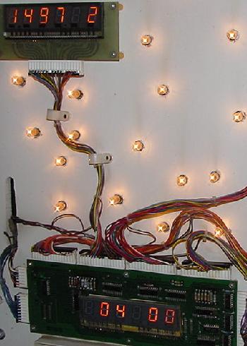
AUDIT MODE:
On system4 to system7 games, the dreaded audit mode.
A Firepower powered-on with dead batteries and/or a
dead IC19 5101 RAM chip, booting into audit mode.
Audit "00" shows the game number (#497) in the
player one score display, the operating system revision
(the preceding "1", meaning "green" flipper ROMs, where
"blue" flipper ROMs have a "2", and yellow flipper ROMs
have a "0"), and the software revision (version "2")
next to the game number. The "00" in the ball-in-play displays
shows audits number zero, and "04" in the credit window
indicates audits (remember "01" is lamp test, "02" is
solenoid test, and "03" is switch test).
|
|
In audit mode ("04 00" in the credit/ball-in-play display, where "04"
is audits, and "00" is the first audit number),
the numbers shown in the player1 score display are the value
for the audit number shown in the ball-in-play display.
For audit "00", which is the software identification
audit, the last number is the game's current software
revision number (version 2 in the above picture).
The middle three numbers are the game number
(i.e. 497 is Firepower; see the
Game List section for all the
game titles and game numbers).
And the first number determines the "flipper ROMs"
version installed. Remember Williams used a color coded system:
- 0 = Yellow Flipper ROMs (system4)
- 1 = Green Flipper ROMs (system6)
- 2 = Blue Flipper ROMs (system7)
These software identification numbers made it easy to see if the
wrong Game and/or Flipper ROM software was installed in the machine.
Note the lack of a code for White flipper ROMs (system3).
This is because the boot-up "software versions" was not implemented until
System4 and the Yellow flipper ROMs, when adjustment were also
stored in memory (system3 used DIP switches for the adjustments).
Williams did the audit mode routine to show instantly upon power-on
that the game's adjustments/audits were lost, and that the batteries needed
to be replaced. The main reason this was done was to protect
the game from having garbage in an adjustment that may put
the game into free play (or some other equally accidental
bad mode), since now all the game's adjustments were store in memory
instead of being "hardcoded" with DIP switches.
With system6 and its memory protection circuit/coin door switch,
it also keep miscreants from drilling
through the bottom of the game and activating the switches to change the
settings (like one quarter equals 25 credits!), since the coin door
now had to be open to change an adjustment/audits.
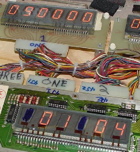
A system3 game (Hot Tip) with dead batteries booting into audit mode.
Here the audit number is in the credit window ("01"), the audit mode ("04")
is in the ball-in-play window, and the value for the first audit ("090000")
is in the player1 score window.
|
|
On system3 games, a dead battery or failed CMOS memory still
comes up in audit mode, but there is no indication of software revisions.
The audits in system3's white flipper ROMs looks a bit different too,
with the audit number in the credit window, and the "04" (to signify audits)
in the ball-in-play window (this was reverse of system4 to system7),
and the audit value in the player1 score display. If the manual-down/auto-up
switch is in the auto-up position, the game rotates through all the audit
numbers automatically also.
3b. When Things Don't Work: Fixing a Dead CPU (LED code, Test EPROM, Blanking)
For info on the Blanking signal, chick
here to jump down to that section.
For info on the Leon's Test chip, chick
here to jump down to that section.
Introduction to CPU/Driver Board Repair.
The System3 to System7 CPU/Driver board combo are a real circuit
board design nightmare. After spending a great deal of time fixing
1977-1985 Bally/Stern pinball and Gottlieb System80 machines, I would
personally have to say the Williams System3 to System7 games
are way worse than 1977-1985 Bally games (Williams sys3-7 is
tied with Gottlieb System80, or maybe is even worse, thanks
to all the bad Scanbe sockets and 40 pin interconnector!)
System3 to System7 games were designed so that a field tech
would only have to swap out a failed board, and then send the board
to the distributor for repair. The boards were
not designed to be diagnosed and fixed on location.
Looking at the Williams "repair" manuals, the instructions tell pretty much
only how to pinpoint which board is bad. The final "fix" of most repair steps
in a Williams manual is to "replace the board".
Unlike more recent games which report many problems,
early Williams board provided little diagnostic help.
This was unlike the approach Bally took with their famous
"seven flashes" diagnostic system (which makes component level
repair pretty easy).
Where Bally took the approach that the boot-up diagnostics were
very important and game diagnostics were not, Williams took the opposite
approach that boot-up diagnostics were *not* important but
game diagnostics were! Hence 1977-1985 Bally games
have the famous power-on seven flash test, but
don't really have a lamp, display, coil or switch test.
Williams system3 to system7 games have basically no significant power-on
test indicator, but do have good versions
of lamp, display, coil and switch tests (assuming that the
Williams game in question will boot up properly!)
Initially, when these games were new,
Williams pinballs were dependable, about as good as Bally games (and better
than Gottlieb' system80). But after a few years, as the Scanbe sockets
got old and the 40 pin
interconnector wore, dependability of these games made them way
worse than Bally (and probably on par with Gottlieb). And with
no power-on indicator system like Bally had, operators didn't
even know where to start with a Williams repair.
It's not that the Williams system is "hard" to fix, it's just time
consuming. Where the Achilles' heel of the Bally system is battery corrosion
and Gottlieb had board connector and ground
issues, Williams System3 to System7's Achilles' heel is the design of
the boards themselves. Passing address and data lines over a 40 pin .156" Molex
interconnector is a bad idea. If *any* address or data line drops out for
even a millisecond, the whole game locks up. Same thing with the Scanbe
sockets; if a single pin become intermittent on any Scanbe socket, the
game locks up. Add vibration to the mix, and things only get worse.
Having some PIAs on the CPU board and some PIAs on the driver
board forced the address and data lines to cross the two boards at this
Achilles' heel (the 40 pin interboard connector). And if the game
locks up when a coil is energized, that can take out more components
on the driver board, making the repair even worse.
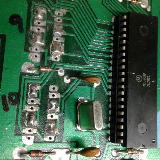
Also some components on the Williams System3 to System7 boards
are obsolete and unavailable. For example, the System3/4 clock chip
(MC6875) is obsolete and impossible to find. This is the companion
clock chip to the 6800 CPU processor.
Luckily, the MC6875 doesn't fail too often. Also the 8T28 and 8T97
chips are discontinued (there is a work arounds for most of those).
But this is why many repair facilities will not repair Williams
System3 or System4 CPU boards.
To make matters even worse, the software contained in the "flipper ROMs"
(essentially the operating system) adds to the problems.
If any of the PIAs can not be found in the exact state the software expects,
this locks up the software, and hence the entire game.
So say the solenoid PIA is partially dead
(common, because of a locked-on driver transistor which cascaded back
to the PIA and damaged it). This
may make a coil or two not function. That's fine; the game maybe could still
be operated and played without a bumper or two. But instead, the whole game locks
up and becomes useless. And because the CPU is locked up, diagnosing the
problem becomes very difficult too.
To add insult to injury, the driver board is an integral part of the
CPU board. That is, the CPU board will *not* run without a functioning
driver board attached! (Unless a special test EPROM is used, which
has only recently became available.) So the whole theory of spliting the system
into smaller components (a separate CPU and separate driver board)
for easier diagnostics is missed*. The two boards need each
other, and are linked together through the incredibly stupid and troublesome
.156" 40 pin interconnector. This is unlike Bally and Gottlieb, where
their CPU boards can be run independently of the driver board, making
diagnosing problems much easier, since the system can be broken down
into smaller, more managable pieces.
* Note there is a trick that allows the Williams CPU board to (semi) boot
without the driver board. The driver board can be completely removed from
the game, and the CPU board booted. If the CPU board is OK (trying to run),
the two CPU LEDs will blink on, then go off, and then come on steady (since the CPU
board is looking for the Driver Board). If installing the Driver Board
locks the CPU (LEDs steady on, no blinking at bootup),
then the CPU board is probably Ok (and there's problems on the Driver Board.)
On a system7 CPU board, if the CPU
were OK (or trying to run) the Numeric Led would blink �0�, go off
and come on steady (looking for the Driver Board).
If putting the Driver Board back in locks up the game ("0" steady on),
then there are some problems on the Driver Board
The Internal System3-System7 Diagnostic Firmware.
AKA, this is NOT "Bally World".
Lastly (really I promise!), the System3 to System7 internal diagnostic
software is very limited. Remember the Bally power-on LED flash test, and
how nifty that is at helping identify bad CPU board components?
Well unfortunately, there is nothing like that in the Williams'
firmware. Either a Williams system3 to system7 CPU/driver board boots,
or it does not. There's not much middle ground here.
The Williams' LED(s) at boot up provide some very basic information,
but nothing like the information a Bally MPU LED provides.
Yes there is a diagnostic test switch SW1 on the Williams CPU board.
But in order for this test to work properly, the CPU board has to be successfully
booted and running! But if the CPU board has successfully booted,
the need for this test is really quite limited.
To make matters even worse, the diagnostic SW1 test, even on a working CPU
board, can confuse even a veteran user. The diagnostics are a memory
test only, and tests the CMOS RAM IC19 (5101)
and the two static RAM chips (IC13/IC16). But
the static RAMs IC13/IC16 rarely die. And the user will already know if the CMOS
5101 RAM is dead well before the diagnostics are run. If the game
boots into "audits" mode, and the CPU batteries are good, it's 99%
for sure the 5101 RAM is dead.
Also, even if the CPU board has seemingly "booted correctly", the
flipper ROMs IC17 and IC20 can still have problems. These two ROMs
hold the diagnostic code, and if one of these ROMs has a problem,
false indications can result from the SW1 diagnostic switch
(but usually the CPU board didn't boot anyway and the
LEDs are indicating a locked-up board,
and these two ROMs don't even get a chance to start working).
To make matters worse, the diagnostic LEDs just tend to confuse the
newbie repair person. For example, the CPU board does not boot,
but the user presses the diagnostic switch SW1 anyway. The LED
reports back the suspected failed component. But that's the problem...
since the CPU board never booted properly, the output from the
diagnostic test CAN NOT be trusted! What ever the test indicates
is surely incorrect, and the newbie is replacing good CPU board components,
based on the failed/incorrect test results (I believe this is called,
"chasing one's tail"). This is especially a problem if the newbie
came from "Bally world", where Bally's LED actually has good
boot-up component diagnostic results.
The bottom line is this:
if the Williams System3-System6 CPU board's LEDs lock-on at power up,
the CPU board is not working! Likewise for System7, if "0" comes
on immediately at power-up, the CPU board is not working. Why
that is happening, well, you're on your own to figure it out!
Because the Williams diagnostic firmware is *not* going to help.
OK, So That's the Bad News. What's the Good News?
The good news is fixing a dead Williams CPU/Driver board is pretty
systematic. The same things seem to cause the same problems,
and it doesn't stray too far off this path too often. The bottom
line is this: all the CPU board and driver board Scanbe sockets need to be replaced.
Change the flipper ROMs and gamerom to EPROMs, to use
less chips/sockets and to replace the old and undependable
original ROM chips. The 40 pin female interconnector needs to be
replaced. The CPU board's 5101 RAM at
IC19 dies often. The driver board's
solenoid and switch matrix PIAs die. Sure lots of other things
can and do happen, but that's the majority of the CPU/driver board problems!
Again, use the simple test to trick the Williams CPU board to (semi) boot
without the driver board. The driver board can be completely removed from
the game, and the CPU board booted. If the CPU board alone comes
on with both LEDs on (no blinking), then the CPU board is faulty.
If the CPU board is OK (trying to run),
the two CPU LEDs will blink on, then go off, and then come on steady (since the CPU
board is looking for the Driver Board). If installing the Driver Board
locks the CPU (LEDs steady on, no blinking at bootup),
then the CPU board is probably Ok (and there's problems on the Driver Board.)
On a system7 CPU board, if the CPU
were OK (or trying to run) the Numeric Led would blink �0�, go off
and come on steady (looking for the Driver Board).
If putting the Driver Board back in locks up the game ("0" steady on),
then there are some problems on the Driver Board
Getting Started on Fixing the CPU Board.
Before Starting...
Before starting to fix a dead CPU/driver board, go back to the
"Before Turning the Game On" sections and follow all those steps.
It's not even worth going on until that work is done. For example,
the power supply needs to be working and outputting the correct
voltages. Also the assumption is that the CPU board's LED(s) are
locked on, or at least flash. If they don't do that, make sure
there is +5 volts getting to the CPU board, and then check the
section below for more help.
Before removing any boards from the game, and assuming the power supply
is working, it's time to do some preliminary diagnostics. Remove the
game's backglass, so the CPU board's LED(s) can be seen (if the CPU
board in question is not in the game, it can be powered up "on the bench"
with an external +5 volt power supply, those details are below).
Right now, before doing anything, remove fuse F2 (solenoid power) and
fuse F3 (lamp matrix power) from the power supply board.
Now go ahead and power the game on, keeping an eye on the LED(s)
on the CPU board. Here's a list of what could happen:
- CPU LEDs come on and stay on (or system7 LED displays zero), with no flash:
The CPU either isn't booting, isn't resetting, or has locked up attempting to boot.
Common problems are bad CPU sockets (Scanbe) or a bad inter-board interconnect
board. Go to the Leon Test ROM section below.
- CPU LEDs flash once (or system7 CPU LED flashes "zero" once), and then turns on
and stays on:
The CPU board booted and then ran into a problem. Most like a ROM related problem,
like bad sockets (Scanbe) or bad ROMs, or a bad PIA on the CPU or driver board.
Go to the Leon Test ROM section below.
- CPU LED(s) flash once quickly then go out, but the score displays do not turn on:
The CPU has started and the game program is (probably) running,
but there is either a ROM problem (sockets),
or the board refuses to execute an IRQ request due to a bad 4020 at IC25 (a common failure point),
or a problem with the score displays (dragging the CPU down), or a blanking problem.
Turn the game off, and replace fuse F3 (the lamp matrix power).
Turn the game on, then turn the game off and on quickly;
if the score displays remain off,
but the game goes into "attract" mode (feature lights flashing), there is a
problem with either the master display driver board or the display circuitry on the CPU
board. Remember system3 games (white Flipper ROMs) do not have an "attract" mode other
than the backglass high score lamp flashing on and off. So for these games,
try starting a game to determine if there is a score display problem (add
some credits and press the start button). If the feature lights do not come on
(or a system3 game can not be started),
Go to the Leon Test ROM section below.
- CPU LEDs flash once then go out and player 1 display shows what looks like an error code:
The game is booting up into "audits" mode. This is good news,
as the CPU/driver board problems are usually minimal. The CMOS RAM memory has
been erased for some reason (dead batteries or bad CMOS RAM),
and this is a warning that all audit and adjustment information
has been forgotten. With the coin door open,
turn the game off and on quickly, seeing if the game
goes into attract mode (might have to do this several times).
If the game comes up in attract mode, then chances are good the CMOS IC19 RAM
chip is Ok, and all that is needed is new batteries or battery holder
(please see the section on batteries).
If the game continues to come up in audits mode, then the IC19 CMOS RAM 5101 chip
is probably bad. Replace this chip (use a socket!), and the game should
be good to go.
- To determine if the problem is the CPU board or driver board,
again, use the simple test to trick the Williams CPU board to (semi) boot
without the driver board.
On a system3-6 game, the driver board can be completely removed from
the game, and the CPU board booted. If both CPU board LEDs should come on,
go off, and then come back on and stay on. If they do, that usually means
the CPU board is Ok, and the driver board needs some work.
Go to the Leon Test ROM section below.
Fixing a Broken CPU Board with Leon's Test EPROM.
Get Leon's CPU Test EPROM.
All the other "Before Turning the Game On" work is done, right?
But the CPU/driver board is still dead. Well now is the time
to get Leon's test EPROM. This chip is really needed to do
any serious diagnosing of the CPU board, as it allows the
CPU board to be run without the driver board. Chances are good you do
not have an EPROM programmer. So you'll need to find someone
to burn this chip into a 2716 EPROM (or 2532 for System7 CPU
boards). The 2716 EPROM code for System3 to System6 games can
be downloaded by clicking here (2716)
(new system3-6 version 11/01/03).
The 2532 EPROM code for System7 can be downloaded by clicking
here (2532) {new system7 version 11/01/03}.
EPROM Tip: If getting an EPROM burned is really a big deal,
the System3 to System6 version of Leon's test EPROM can
be "doubled up", burned
into a 2532, and used in *any* System3 to System7 CPU board.
Yes the 2532 is twice the size of the expected 2716 at IC17
on a System3 to System6 CPU board. But because of the way
a 2532 EPROM is addressed, the added address space of the 2532
will just be ignored by the System3 to System6 CPU board.
But there is a downside to this; Leon's memory test will *not*
work in a system7 CPU board.
This is because memory for System3 to System6
is at locations $0080 to $0100, and in System7 memory is located
from $0000 to $0100 (but the basic part of Leon's test ROM will
work, but the memory test will not). This works in a pinch if
the correct EPROM is not available.
After the above EPROM code is downloaded and burned into the
appropriate EPROM, remove all the existing ROM/EPROM chips
from locations IC17, IC20, IC14 (and IC21, IC22, IC26, but
there should not be any chips in those locations anyway if
the CPU board was converted to EPROMs and new sockets installed).
Now installed Leon's test EPROM into the flipper ROM socket at IC17.
Note: Leon's chip will work with the other ROM chips installed.
This happens because Leon's test program starts at the "boot up" memory
location, and it does not access the other ROM chips. So basically the
other ROM chips get ignored, as Leon's chip is accessed first at
power-on, after the CPU board resets. BUT I highly recommend removing ALL the
other ROM chips! If one of the other ROMs is bad (shorted), it could "lock up"
the CPU board. By removing them, it's just one less thing to go wrong.
Separate the CPU board from the Driver Board.
The test EPROM is burned and installed at IC17. Now it's time to
separate the CPU and driver boards. Remember how I mentioned the
CPU board would *not* work without the driver board? Well that's
correct, except when using Leon's test EPROM! This is the *only* firmware
that will allow the CPU board to run without the driver board attached
(thank you Leon!) This alone makes diagnosing a bad CPU/driver board
much easier.
IMPORTANT: Leon's test EPROM can be run with the CPU board
installed in the game, but this is *not* recommended.
The test EPROM will toggle all the
PIA outputs. If installed in a game, this will turn all the
lamps and solenoids on and off! If the test EPROM really must
be run in the game, make sure to remove fuses F1 (H.V.), F2 (solenoids),
and F3 (lamp matrix) from the power supply board,
and/or all the connectors are removed from the driver board and the
CPU board (except CPU connector 1J2).
This will ensure the solenoids and lamps and score displays are not energizing.
For example, if the lamp matrix F3 fuse is not removed, a
full 18 volts (not strobed!) will go to the CPU controlled lamps, and
burn all of them out instantly! It is also a good idea to remove the power
going to the sound board as the PIA outputs could toggle the sounds.
Removing power supply fuses F1 (H.V.), F2 (coils), and F3 (lamps) before
powering-on with the Leon test ROM and the boards mounted in the game.
|
|
Booting the CPU board on the "Bench" with an External Power Supply.
The next trick to fixing a CPU/driver board is to move the boards
from the game and to the work bench. In order to do this, an
old AT style computer power supply that outputs +5 volts DC (and +12 volts)
is needed. These are pretty easy to come by, any computer store should
have one for free to $20 dollars (heck new AT computer power supplies
can be purchased too for less than $30). An old video game switching
power supply can also be used.
Newer ATX power supplies can also be used, but these do not have a physical power
switch. Instead they get a signal from the computer's motherboard connector
to turn the power supply off. But these power supplies can be fooled to turn
on when their power cord is plugged in. Just tie the green /PS-ON wire
(power supply on, active low, normally
pin 14 on the motherboard connector) to the black COM ground wire.
(a diagram of the 20-pin ATX connector can be found at
wired.hard.ru/data/atxpower.shtml).
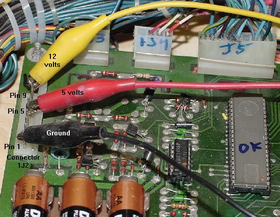
Hooking up a system3 to system7 CPU board to an external PC power supply.
The red wire is +5 volts, the yellow wire is +12 volts, and the black wire is ground.
|
|
After the power supply is obtained, power it up and figure out which
wires are the ground COM (usually black), +5 volts DC (usually red), and
+12 volts DC (optional, but usually yellow). Use a DMM
to test the voltages. Turn the power
supply off. Now get three alligator clip test leads, and hook up
the power supply to the CPU board's connector 1J2 as follows:
- Ground (black) = CPU board 1J2 pins 1,2,3 (connect to pin 1)
- +5 volts (red) = CPU board 1J2 pins 4,5,6 (connect to pin 5)
- Unregulated +5 (or +12) volts = CPU board 1J2 pin 9*
* Is the Unregulated +5 Volts Needed?
Williams calls this "unregulated +5 volts", but in reality it's
actually closer to unregulated 12 volts.
System6 and System7 CPU boards may be easily jumpered to work on only +5 volts,
with no need to use a power supply's +12 volts too.
Interestingly, System3 and System4 CPU boards also do not require the +12 volts
IF they have the "reset modification" performed
(in the CPU board modification section).
I personally don't recommend using the +12 volts unless it is needed,
as it's just another thing to mis-connect, and most CPU boards don't need it.
To get around not connecting power to the unregulated +5 volt power pin
on System6 to System7 CPU boards,
try the board first without the unregulated +5 volts. If it doesn
work, use an alligator jumper clip and do this:
Connect the power supply's +5 volts
(the electroylic cap C23's positive lead) to resistor
R27 (see which side of R27 in the bullet points below).
Because the layout of System6 and System7 is different, pay
particular attention to the instructions below. Because one side
of R27 is ground, and connecting +5 directly to ground would cause
the power supply to short. So be careful which side of R27 is used!
In all cases, cap C23 and resistor R27 are just to the right of connector
1J2 on the CPU board.
- System6 CPU board: alligator clip on
the TOP side (positive lead) of C23. Connect the other jumper
to the bottom lead of R27.
- System7 CPU board: alligator clip on
the BOTTOM side (positive lead) of C23. Connect the other jumper
to the BOTTOM lead of R27.
At Power-Up, the LEDs or 7-Segment Display Does not Come On.
On system3 to system6, if the LEDs don't come on at all, or on system7
the segment display doesn't come on, there is a problem!
This is usually a sign of a short on the board (battery corrosion?) or
no power. Make sure the power is hooked up properly to the board.
On System 6/7 CPU boards, check test point TP9 for +5 volts.
On all system3-7 CPU boards, also test for +5 volts at pin 8
of the CPU chip IC1 (ground is IC1 pin 1) and at
interconnector pin 1 on the far right.
If there's no +5 volts at the CPU chip,
then trace back through the power circuit to see
where it's losing power. Check to make sure there isn't a short to ground.
There are capacitors (.01 mfd non-polarized)
at the Vcc (+5 volt) connection of each
chip on the board to ground. Check each one of these for a
short. Also check the board very carefully for solder splashes.
Remember a prior repair may have gone bad and the board was
junked for this reason.
On System3 to system6 boards, check for +5 volts at IC2 pins 2,5,16
(the 8T28 that drives the LEDs). Also remember
both LEDs could be bad!
The LEDs will always come on at power-up unless turned off by an executing program
on the CPU board. If there is proper voltages on the board, but no
voltage at pins 2 and 5 of IC2, check for a running CPU chip (see below).
If there is CPU activity on the address and data lines,
then the problem is most likely IC2 (8T28) on system3 to system6 boards.
On System7 CPU boards, if there is no activity on the 7-segment display,
it is common for IC34 (7447) segment
driver chip to fail. This will give a false indication that the board is
completely dead or that there's no power.
Using a logic probe, test for pulsing at IC1 pin 15 of the CPU chip.
If there is activity there, then the problem is most likely IC34 or
the segment LED itself. Also if the LED comes on and stays on
(even though the game is seemingly working fine),
often IC2 (74125) has shorted internally.
Note two test LEDs (like on system3-6 CPU boards)
can be added to the System 7 CPU board. This will allow
testing to the board before replacing IC34 and/or segment LED.
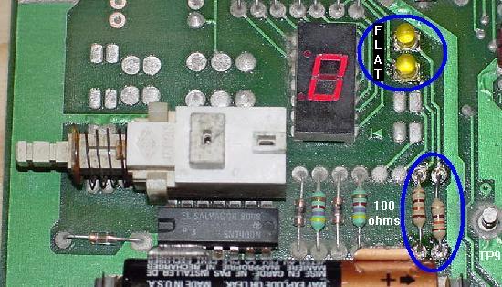
All that is needed is two LEDs and two 100 ohm 1/4 watt
resistors. Solder the two resistors into the board, just to the left of test point
TP9. The LEDs then should be soldered into the two top pads pairs next
to the segment LED, with the flat side of the LEDs towards the 7-segment LED.
With the two LEDs installed, they will "flash" just as the LEDs flash on
system3 to system6 CPU boards.
Adding LEDs to a System7 CPU board. Note the flat side of the LEDs goes
towards the 7-segment display, and the new LEDs mount on the upper two
solder pads (of the four pairs). Two 100 ohm resistors are also added next
to TP9. If the 7-segment LED or IC34 that drives the 7-segment display is
bad, the installed LEDs can be used to diagnose other CPU board problems.
|
Step 1: How the CPU board boots (or "Getting Started").
Ok, so the CPU board is all ready, with the test EPROM installed,
power supply connected, and the driver board removed. Now we
can power on the CPU board. But first, it would be helpful
to know what is happening, and how to check it.
Here are the steps involved in a correctly booting CPU board.
In the case of a dead CPU board,
each step can be diagnosed with a DMM and/or logic probe.
- Make sure there is +5 volts at CPU IC1 pin 8 (and IC1 pin 35 on
system6/7). There should also be a slightly lower
voltage at IC1 pin 2, and ground at IC1 pins 1,21.
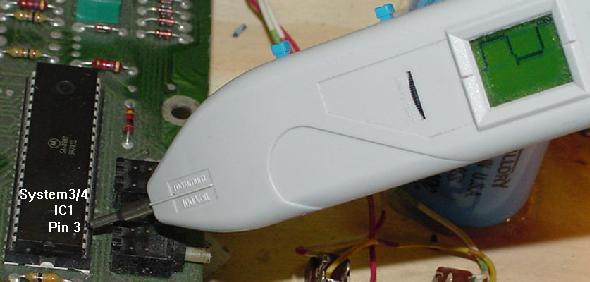
- At power-on, the /RESET (U1 pin 40) 6800/6802 CPU chip is held low for
about 50 milliseconds by the reset circuit. This gives the power
supply a chance to stablize the +5 volts before the CPU chip
starts to "boot".
- Next the /RESET pin 40 goes high, and the CPU chip begins
to execute a startup program inside IC17 (the Flipper ROM). Using a DMM connected
to ground and U1 pin 40, check that the voltage comes up to at
least 4 volts (from zero volts) when the CPU is first turned on.
If the reset pin is not going high (to at least 4 volts),
suspect CPU transistors Q1-Q4, Q6-Q9 and diodes D19,ZR1,ZR2 on System6-7,
and CPU transistors Q1-4, Q6 and diodes D17-D18,ZR1 on System3-4.
Using the schematics, work back through the circuit,
testing each transistor, diode and resistor until the faulty
component is found.
Interestingly, the reset circuit can be overridden by connecting +5 volts
to IC1 pin 40 of the CPU. If the reset circuit is the only problem, the CPU should
start when +5 volts is applied to pin 40. This is a good method if testing
for a bad reset circuit.
On MPU boards with a flakey reset, one that works sometimes,
check if cap C68 (0.1 mfd ceramic) is present (it sticks up just below IC14 pin #1.)
This cap is not always installed on sys3/4 MPU boards, and it is part of
the Reset circuit. It may be causing a problem. If it is present try replacing
or simply removing it, if missing try adding it. Sometimes it makes a difference,
sometimes not.
- The "clock" circuit must also be running.
This gives the CPU chip a timing pattern.
On System3 and System4 CPU boards,
the clock can be seen with a logic probe at chip U1 pins 3,36,37.
Also the the same signal can also be seen
at the MC6875 (left of the crystal) IC5 pins 7,13,15
(IC5 pin15 feeds CPU IC1 pin 3, and IC5 pin13 feeds CPU IC1 pin36,37).
On system3 to system6, hopefully
all the signals are at IC5, as this chip is obsolete.
If there is no clock signal on the IC5 MC6875 chip,
first replace the crystal as they are much cheaper
than trying to find the obsolete MC6875 chip.
The manual calls for a 3.58 Mhz crystal,
but 3.579545 Mhz is really what is available today,
and this works fine.
The clock signal on System3 and System4 CPU boards at IC1 pin 3.
This same signal can also be seen at IC1 pins 36,37.
|
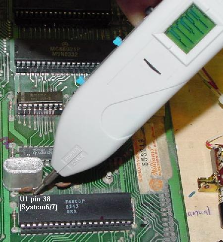
On system6 and system7 CPU boards, the clock is slightly different because
Williams replaced the 6800 with a 6802/6808 CPU processor. With this
upgrade, the obsolete MC6875 chip was no longer needed, and hence was
eliminated. The clock circuit on the 6802/6808 is built into the
CPU chip itself, so the only external clock parts are the crystal
and two capacitors. On system6/7 the clock can be seen
on the CPU chip U1 at pins 38,39
(which feeds to the 3.58 mHz or 3.579545 Mhz crystal CR1,
and the two capacitors C25,C26 which are 27 pF).
If the clock is not pulsing on system6/7,
replace the crystal and check caps C25,C26.
If still no clock, then the IC1 CPU 6802/6808 chip is bad.
The clock signal on System6 and System7 CPU boards at IC1 pins 38,39.
|
- The CPU chip now begins to run a program in the IC17 ROM chip
(this is one of the Flipper ROMs). In order to do this, the
address and data lines fetch the information from the ROM chip,
and the CPU chip executes it. The RAM chips are also used in this
processes too. If everything checks out prior
to this step, but the CPU board's LEDs lock on or lock off,
suspect the EPROM IC17 or its socket (also suspect
all the other EPROMs and their sockets, but with Leon's test
EPROM, there shouldn't be any other ROMs installed!)
All the IC17 EPROM address lines A0-A7 (pins 8-1), A8-A10 (pin 23,22,19),
Chip Select2 (pin 20), and data lines D0-D7 (pins 9-11,13-17)
on the EPROM IC17 chip can be checked with a logic probe.
They should be pulsing for the most part, except for maybe address lines A8-A10
(pins 23,22,19). If any are missing (not pulsing), suspect a broken or shorted
circuit board trace (use the DMM's continuity function, as all the address/data
lines go from the CPU's buffer chips to each of the EPROMs and RAM chips,
though the pin numbers for the RAM chips will be different from the above EPROM
pin numbers).
Also check the CPU chip IC1 for pulsing at address lines A0-A7 (pins 9-16),
data lines D0-D7 (pins 33-26), and perhaps address lines A8-A10 (pins 17-19).
- There is a chance the CPU chip at IC1 could be bad.
It doesn't happen often, but it does happen. Remember system3 and system4
CPU boards use a 6800 or 68B00 CPU chip, and system6 and system7 CPU boards use
a 6802 or 6808 CPU chip. A 6800 can not be put in a system6 board, and
likewise a 6808 can not be put in a system4 CPU board! Keep this in mind.
Note in System 6 and system7 CPU boards a 6802 or 6808 CPU chip can be used.
Most system6/7 boards all shipped with 6808 chip, as these are slightly cheaper
than the 6802 (which has onboard RAM). If a CPU board originally had a 6808,
either a 6802 or 6808 CPU chip can be used without any jumper changes.
If a system6 CPU board has a 6802 chip and a 6808 is desired instead,
check to ensure that CPU jumper J1 is installed and that a 6810 RAM chip is
installed on the CPU at IC13. The 6802 CPU chip is identical to the 6808, except it
has internal RAM. This internal RAM can be used instead of the 6810 at IC13,
on the System6 CPU board ONLY (this is why the system6 CPU board's
IC13 is socketed and IC16 is soldered). I have never seen a System 6 board configured like
this, but it could be done.
- At power-on, the blanking signal (pin 37 of the interconnector)
should go from low to high (around 4 to 5 volts),
just like the reset line. The blanking
signal is a flag that goes to the driver board and says, "Hey, the CPU is up
and running". When the driver board sees the high blanking signal, the driver board's
PIA outputs are enabled, allowing the solenoids, lamp matrix and score displays to work.
If there is a problem on the CPU board (or on the Driver board), the blanking
signal will never go high. Note with Leon's test chip installed, the blanking signal
will alternate from low to high once every second.
- Check the IRQ circuit, as generated by IC25 (4020) on system6/7 CPU boards,
or IC23 (556) on system3/4 CPU boards.
Using a logic probe, check IC1 pin 4 for the a pulsing IRQ signal
(or check TP5 on System6/7 CPU boards).
- Don't forget to check the CPU socket IC1, especially if it is
a Scanbe socket. That was replaced right?
How to Tell if a CPU Board is Locked-up or Good.
The following applies to CPU boards installed with game sofware
(and *not* Leon's test EPROM).
For System3 to System6 CPU boards with game software installed,
a good working and fully booted CPU
board will, at power-on, flash both LEDs for a moment, and then turn both LEDs off.
A locked-up System3 to System6 CPU board will have either or both of the LEDs
turned on and stay on when the CPU board is powered on.
On System7 with game software installed, a good fully working and booted CPU board
should flash the 7-segment LED or the two small LEDs next to the 7-segment,
seeing a "0" briefly on the 7-segment display. Then
the LED(s) go out and should *not* come back on.
If there is a "0" from the instant the power is turned on,
with no flicker or activity, then the System7 CPU board is locked up.
In addition, if the CPU board is up and running, the blanking signal
will be high (around 4 volts). This is pin 37 of the 40 pin interconnector,
or CPU connector IJ3 pin 4. The blanking signal can be fooled into being
high on a non-working CPU board, or it can never go high on an otherwise
working CPU. But for the most part, a working CPU board will have a
high blanking signal.
Running Leon's EPROM "bare bones."
The minimum chips needed to run Leon's EPROM at ic17 are
the 6800 (or 6808/6802 on sys6) processor, the
6821 PIA, and of course Leon's EPROM at IC17. (Support TTL chips
are of course needed too!)
All the other ROMs/EPROMs can be removed. Also the two 6810 RAM
chips can be removed. And of course the 5101 RAM can be removed.
But Leon's EPROM won't run if the 6821 PIA on the CPU board is
missing. I know seems weird, but that's how it is. This of course
begs the question, "why"? Frankly I'm not sure, and it is a
short coming of the Leon EPROM. But that's how it is.
How to Tell if Leon's Test EPROM is Running.
The most obvious thing that will happen if Leon's test EPROM is
running correctly is this: On a System3 to System6 CPU board,
the two LEDs on the CPU board will
start flashing together, at about one second intervals. If the
reset and clock circuit are working, and the address and data lines
are active, both LEDs should start flashing
about one second after the power is applied to the CPU board.
On a System7 CPU board, a "zero" will flash every second on the
7-digit LED display.
The LEDs Come On & Stay On (or 7-segment display shows "0").
This is certainly the most common problem, and perhaps the most
difficult to fix. By default, the two system3-6 LEDs or all the system7 LED
segments come on and stay on when powered on. This happens because that's
what the hardware dictates; the LEDs/segments do not turn off until
the program in IC17 turns them off.
The Leon test ROM and the game program do this by setting the output
ports PA6 through PA10 on CPU IC18 (the 6821 display PIA) low.
If the test or game program isn't running, these
ports remain high, and the LEDs/segments stay on.
When the MPU board is powered on, the CPU chip
attempts to read addresses $FFFE and $FFFF in
EPROM chip IC17 (the test ROM or flipper ROM 2) to obtain the jump
address for the program to execute. This program then takes over
and controls the LEDs. If the program is not able to start reading IC17,
then the LEDs stay locked on.
The standard game software in IC17 then tries
to read and write to the RAM chips IC19,
IC16, IC13, and to all the PIAs on both the CPU and driver board
(this of course assumes that the boot up process got far enough
to run the program in EPROM IC17!)
If there is any problem encountered, the program will
lock up and not turn off the LEDs.
The Leon test ROM however will run even if the PIAs or RAM chips are bad
(or missing for the most part), so this narrows down the areas to check
if the test ROM doesn't start its alternating LED on and off rythmic flash
pattern.
Good Reset and Clock but No 'Leon' Alternating LED Flashes.
So the reset and clock test good, but the CPU board, with Leon's test EPROM
installed, is still dead! What could it be? According to Leon's documentation,
if the U1 CPU chip 6802 is good, his program should run (so try replacing
the U1 6802/6808 chip with a known good chip, just to make sure). BUT I find this to
not be the case. For example, the following things could make the CPU board
not run Leon's program:
- Bad IC1 chip or socket (6802/6808 microprocessor).
- Bad IC17 EPROM chip (Leon's test EPROM).
- Bad IC17 socket (or any socket on the CPU board!)
- Bad IC18 PIA (6821) chip.
- Bad IC19 chip 5101 RAM. A really fried 5101 can stop Leon's program from working.
If there is any question, remove the 5101 chip completely (Leon's program will work
with no 5101).
- Bad IC11 (74LS10) and/or IC12 (7408) which are in the chip
selection circuits.
- Address or Data line is broken (board trace broken). Using
a DMM, make sure the address and data lines all show continuity
to the EPROM (IC17), RAM IC13/IC16/IC19 chips,
and PIA chip(s).
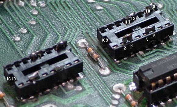
- Bad buffer chips at IC9/IC10 (CPU boards prior to System6A only).
Some of the above chips can be just removed from the CPU board
with Leon's test EPROM. For example, the CMOS RAM at IC19 (5101)
can be removed. Also the static RAMs at IC13/IC16 can also be
removed. Removing these chips on a dead CPU board with Leon's
test EPROM is a good idea. If these chips have a short, removing
them may allow the CPU board to boot. This especially applies
to the 5101 chip at IC19.
If the CPU board PIA at IC18 is bad,
it may prevent Leon's program from flashing the LEDs. Using a
test LED (as decribed below) and *not* a logic probe,
connect the non-resistor end to +5 volts, and touch the other resistor lead of the LED
to the CPU IC1 pin 15. If the test LED flashes on and off about once a second,
then the test program is running, and the CPU board PIA at IC18 needs to be replaced.
The next thing to check now is if the CPU chip is
running the program in the test EPROM. Use a logic probe and test CPU IC1
for pulsing activity on the
address lines A0-A7 (pins 9-16),
data lines D0-D7 (pins 33-26) (and perhaps address lines A8-A10 pins 17-19).
If the CPU is running a program, there should be some pulsing on these pins.
If even one of the A0-A7 or D0-D7 pins is low or high (not pulsing), then the CPU can not
do its job and properly run the program in IC17.
If there are pulsing signals on just some of these pins, then the CPU is trying to
run, but the test program can't run correctly.
For both the address and data bus lines,
use a DMM and check the continuity between lines.
There should be no shorts between any of the data and address lines!
Use a DMM and start with address line A0,
checking continuity between IC1 address lines A1 through A15
(IC1 pins 9-20, 22-25), and data lines D0 through D7
(IC1 pins 33-26).
Solder splashes and solder bridges are quite common, especially if chip sockets
have been replaced during previous repairs. If
a socket was replaced, or testing a board that
never worked, a previous repair attempt may have
resulted in a short between lines.
While testing the address/data lines, its a good idea to test
address and data line continuity between chips.
That is, does address line A0 go
from IC14, to IC17, to IC20 (and to IC26 on System7 boards),
and finally back to the data and address buffer/amplifier chips (except on
system6a CPU boards) and the CPU chip IC1 (more on these buffer/amplifier
chips below).
Address Bus Signals.
The address signals generated by the CPU chip are not
strong enough to work throughout the CPU and driver board.
To fix this problem, "amplifiers" are used to boast the signals.
This is done by two 8T97 chips at IC3,IC4.
If these chips fail, the address lines can be blocked or
not amplified, and the CPU board will not run.
Luckily these chips IC3/IC4/IC8 are easy to check using a logic probe.
The CPU chip IC1 is connected to IC3/IC4/IC8's input even numbered pins 2-6,10-14,
and the rest of the address bus is connected to the ouput odd
numbered pins 3-13.
For example, the address signals should be identical on
both pin pair (input and output):
- CPU A0 pin 9 to IC4 pin 2, then IC4 pin 3 to address bus A0.
- CPU A1 pin 10 to IC4 pin 4, then IC4 pin to address bus A1.
- CPU A2 pin 11 to IC4 pin 6, then IC4 pin 7 to address bus A2.
- CPU A3 pin 12 to IC4 pin 10, then IC4 pin 9 to address bus A3.
- CPU A4 pin 13 to IC4 pin 12, then IC4 pin 11 to address bus A4.
- CPU A5 pin 14 to IC4 pin 14, then IC4 pin 13 to address bus A5.
- CPU A6 pin 15 to IC3 pin 2, then IC3 pin 3 to address bus A6.
- CPU A7 pin 16 to IC3 pin 4, then IC3 pin 5 to address bus A7.
- CPU A8 pin 17 to IC3 pin 6, then IC3 pin 7 to address bus A8.
- CPU A9 pin 18 to IC3 pin 10, then IC3 pin 9 to address bus A9.
- CPU A10 pin 19 to IC3 pin 12, then IC3 pin 11 to address bus A10.
- CPU A11 pin 20 to IC3 pin 14, then IC3 pin 13 to address bus A11.
- CPU VMA pin 5 to IC8 pin 14, then IC8 pin 13 to VMA signal bus.
- CPU A12 pin 22 to IC8 pin 12, then IC8 pin 11 to address bus A12.
- CPU A13 pin 23 to IC8 pin 10, then IC8 pin 9 to address bus A13.
- CPU A14 pin 24 to IC8 pin 6, then IC8 pin 7 to address bus A14.
- CPU A15 pin 25 to IC8 pin 4, then IC8 pin 5 to address bus A15.
- CPU R/W pin 34 to IC8 pin 2, then IC8 pin 3 to R/W signal bus.
Finally IC8 handles address lines plus the R/W (Read/Write)
and VMA (Valid Memory Address) lines.
If identical signals are not seen on each pin pair shown above, then replace the offending
8T97. The part number is obsolete, but can be replaced by a 74LS367 or 74LS365.
Also if an address line is missing, use the appropriate IC3, IC4, or IC8 chip
as an "anchor point" for your DMM set to continuity. This way continuity can
be check for the missing address line between the ICx chip and the PIA, ROM and RAM chips.
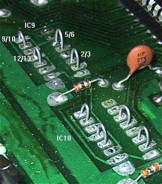
Diagnosing & Removing Data Bus Chip IC9/IC10 (Prior to System6A).
These two CPU board chips
are only needed if using the 3624 masked ROMs on pre-System6A CPU boards
(another good reason to use EPROMs). Otherwise, these
bus transceiver chips IC9,IC10 can be removed (Williams did this
on System6A CPU boards). This is good news, as
these 8T28 buffer chips at IC9,IC10 are hard to find, and they do fail.
The data bus was originally designed in the same manor
as the address bus with two data buffer transceivers chips.
The are transceivers since signals go both way on the data bus, and
are used to amplify the data signals. On
System3-6 CPU boards these are the obsolete 8T28 chips. On the System7 CPU boards one
(avialable!) 74LS245 is used at IC9. System 6A boards eliminated the data buffers
entirely.
I personally don't recommend removing these chips unless they are known to
have a problem. There is some risk involved (see below).
How does someone know if IC9/IC10 are bad? (Remember, all this
only applies to System3 to System6 CPU boards.) This is done in the same
manner as the address buffer 8T97 chips mentioned above.
Using a logic probe, look at the input signals to the IC9/IC10
chips. The output signals should look identical (pulsing). If they are
not, there's a good chance the chip is bad.
Data lines D0-D3 are connected to IC10, and data lines D4-D7 are
connected to IC9.
The CPU data lines are connected to pins 2/4, 5/7, 9/11 and 12/14 of IC9 and IC10.
The data bus is connected to pins 3,6,10,13. The same pulsing waveforms
should be seen on the pins 2/4-3 combination, 5/7-6, 9/11-10 and
12/14-13. If not getting the same readings on both input and out sides,
then the chip is bad.
| U1 6800 |
IC9 Input |
IC9 Output |
|
U1 6800 |
IC10 Input |
IC10 Output |
| Pin 29 (D4) |
Pins 2,4 |
Pin 3 |
|
Pin 33 (D0) |
Pins 2,4 |
Pin 3 |
| Pin 28 (D5) |
Pins 5,7 |
Pin 6 |
|
Pin 32 (D1) |
Pins 5,7 |
Pin 6 |
| Pin 27 (D6) |
Pins 9,11 |
Pin 10 |
|
Pin 31 (D2) |
Pins 9,11 |
Pin 10 |
| Pin 26 (D7) |
Pins 12,14 |
Pin 13 |
|
Pin 30 (D3) |
Pins 12,14 |
Pin 13 |
Remember System7 CPU boards use a single 74LS245 data buffer.
The pairs are a bit like the address
buffers, so make sure the same readings are seen on both sides
of IC9. The pin pairs are IC9 pins 2/18,
pin 3/17, pins 4/16, pins 5/15, pins 6/14, pins 7/13,
pins 8/12 and pins 9/11.
Shorting pins 2&3, 5&6, 9&10, 12&13 of IC9 and IC10. This allows the removal
of these chips, if they are bad.
|
Another method of shorting pins 2&3, 5&6, 9&10,
12&13 of IC9 and IC10. Picture by Mark.
|
Yet another method of shorting pins 2&3, 5&6, 9&10, 12&13 of IC9 and IC10.
|
Here are the steps to removing the chips at IC9 and IC10 on a pre-System6A CPU
board. I personally prefer to do this to a working CPU board, but obviously
this is not alway possible!
- Desolder the chip at IC9.
- Install a socket at IC9.
- Install Leon's test EPROM at IC17.
- Remove the 5101 RAM at IC19 (this is important!) Hopefully this
chip is in a socket (it should be, as it is a high failure item).
- Using an old discarded dead scrap chip, cut two legs off the chip,
and insert them into pins 2 and 3 of IC9. With the legs installed
in the socket, solder to tops of the two legs together so they
are connected (shorting pins 2 and 3 of IC9 together).
- Cut two more legs off the discard dead scrap chip,
and insert them into pins 5 and 6 of IC9. With the legs installed
in the socket, solder to tops of the two legs together so they
are connected (shorting pins 5 and 6 of IC9 together).
- Cut two more legs off the discard dead scrap chip,
and insert them into pins 9 and 10 of IC9. With the legs installed
in the socket, solder to tops of the two legs together so they
are connected (shorting pins 9 and 10 of IC9 together).
- Cut two more legs off the discard dead scrap chip,
and insert them into pins 12 and 13 of IC9. With the legs installed
in the socket, solder to tops of the two legs together so they
are connected (shorting pins 12 and 13 of IC9 together).
- If doing this modification to a working CPU board,
power up the CPU board and test the work (with the 5101 RAM removed).
If all went well above, repeat steps 5 through 9, but with IC10. After
the board is up and running, replace the 5101 RAM at location IC19.
The reason this chip was removed is simple. If a mistake was made in
the above procedure, it will FRY the 5101 RAM! These chips are
hard to get and somewhat expensive now, so it's a good preventitive
measure to remove the chip while testing this procedure. If the
board won't boot, and the two LEDs are locked on, either there
are other problems with the board or some mistake was made in
the above installation.
Chip Selection.
All the EPROMs and PIAs on the CPU and driver board share the same data and address
bus. For the memory locations the CPU is trying the read from
or write to, it needs to "select" the proper chip. The EPROM chips are
selected using a chip selection circuit (the PIAs are
selected directly by the address lines).
If the chip selection circuit is bad, the program code
will never get accessed and the CPU board will stay
locked. Use a logic probe, and check EPROM chip IC17 pin 20 (the chip select
pin) for pulsing activity.
If there is none, then the EPROM chip is not being selected.
System3/4 CPU boards use IC15 (7442), IC11 (7410) and
IC25 (7402) to accomplish this.
System6/7 CPU boards use IC15 (74LS139) and IC11 (74S10).
If any of these chips are bad, the CPU board will be locked.
The Read/Write lines.
The "R/W" line is the signal that the CPU chip generates to
tell a chip it wants to read or write data from it.
This line is high for a read and low for
a write. When the Leon test chip is running, this line should be high.
The R/W line passes through the data buffer chip IC8 (pins 2 to 3),
so a bad gate in this chip can lock the CPU board.
The Valid Memory Address line.
The 6800 series of microprocessors do not always
place a valid memory address on the address bus,
so a VMA signal is required to verify a valid memory address.
The VMA line is high whenever a valid address
is placed on the address bus, and is used as part of the
chip selection circuits. If the VMA line never goes high, then a memory
address will never be selected.
The VMA line originates on the IC1 pin 5 CPU chip,
and passes through the data buffer chip IC8 pins 13,14
(System 3/4 CPU boards have some additional logic chips on the
CPU side of the VMA line, including IC7, IC11, IC12).
Check the VMA at the IC1 pin 5 CPU chip and IC8 pin 14,
as these pins should be high.
Last Resort.
All of the above steps have been done, and
everything looks fine. What now? Looking at the
schematics there are a number of support logic chips in
addition to the chips discussed above. These
are miscellaneous gates that seem to work with almost
everything on the CPU board. It may be
tempting to start replacing these chips since
everything else has checked out or has been done.
Just be aware that only
IC11 (74LS10) and IC12 (7408), which are in the
chip selection circuits, would prevent the test
ROM from booting (in addition to all the chips
mentioned above!)
So if there's nothing else,
replace these two chips.
CPU Chips Not Needed to Run Leon's Test ROM.
When running Leon's test ROM, I have found there are some chips
that are not necessary for his test ROM to boot. On a system3/system4
CPU board, this includes
IC6 (74154), IC12 (7408), IC13/IC16 (6810), IC19 (5101) and
and the ROMs at IC14/IC20/IC21/IC22/IC26.
On system7 CPU board, the list is a bit different, as there are
a lot more chips not needed by Leon's test ROM. System7 CPU chips not needed to run
Leon's test ROM include IC5 (74LS02), IC6 (74154), IC10 (4071),
IC11 (74LS10), IC12 (7408),
IC13/IC16 (2114 RAM), IC19 (5101 RAM),
IC25 (4020), IC35 (sound PIA) and the
ROMs at IC14/IC20/IC26.
Leon's Test Chip is Running, Now What?
So Leon's test EPROM is installed, and the CPU board is
booted and running (that is, the reset and clock sections
of the CPU board are working). Both CPU LEDs should be blinking
about once a second (on system7 CPU boards, the seven segment
display will blink "0" every second). Also, if the CPU board is
in a game (remember to remove fuses F2/F3),
a "0" may flash on and off on two score displays.
All this signifies that Leon's test program is running.
What his test program is doing is testing all
the PIA chip(s) on the CPU board and driver board (if attached,
which it's *not* right now!)
PIA inputs are tested as outputs by Leon's test program;
this puts the inputs (and hence then the outputs)
of PIA chip(s) PA0-PA7 high, then low, high, then low,
over and over again. While Leon's program is doing this,
the PIA's pins can be easily viewed alternating high and low
using a tester LED or a logic probe.
Though this isn't the perfect test method,
any repair person will say they never see a PIA working in output that
did not work at input.
The structure of the PIA chip is complex and any
damage to the output pins (and inner structure) by over voltage or over
current always affects the whole PIA's input/output at that particular pin.
At this point a logic probe and a "tester LED" is needed.
If a logic probe is not available, go to Radio Shack
and buy one for $20.
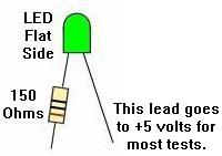
Building the "Tester LED".
The "tester LED" needs to be
contructed using a
LED and a 150 ohm resistor.
Solder the resistor to the FLAT SIDE of the LED.
A wire can be soldered to the non-resistor leg of the LED (or
just connected an alligator test lead). The wire or alligator
test lead will then (normally) be connected to +5 volts.
Use the resistor lead on the LED as a
test probe lead.
I personally have found it easier to probe with the resistor side
of the LED, hence the tester is assembled in this manner.
The "tester LED" construction.
|
The nomenclature in this document assumes the user has assembled their
LED tester as indicated above, and that the LED was correctly manufacturered.
Unfortunately there are some goofey LEDs out there
sometimes sold by liquidators or Radio Shack
that have the flat side of the LED incorrectly marked. This situation
can also be simulated if someone soldering the resistor to the
round LED side. In this situation the user would need to put the
positive round LED side (resistor) to +5 volts and use
the negative (flat) side to probe. The answer to this problem is to correctly
assemble the LED tester. And to buy
LEDs from a reputable source like Digikey or Mouser, so a mis-manufacturered
"liquidation stock" LED is not used (this problem happens
more often than it should!) Unfortunately Radio Shack often buys these
liquidation stocks from manufacturers, so their LEDs are generally
not the best to use. Technically speaking which leg of the LED the
resistor is connected does *not* matter (it will work either way!).
BUT the results seen will be different than documented here. That's the
why the LED tester is assembled in the manner stated above.
Removing power supply fuses F1 (H.V.), F2 (coils), and F3 (lamps) before
powering-on with the Leon test ROM and the boards mounted in the game.
| |
|
Testing the CPU PIA Chip(s).
Now use the tester LED or the logic probe to check each of the PIA's outputs.
Personally I prefer using the tester LED for this, as the
tester LED indications are very clear (a logic probe can show
noise, and is often confusing).
Connect the non-resistor lead of the tester LED to +5 volts
(TP9 on system6/7 CPU boards, or interconnector pin 1 on the far right).
Use the resistor end of the tester LED to probe each PIA pin
desired. If being tested in the game, be sure to remove power supply fuses
F1 (H.V.), F2 (coils) and F3 (lamps) before powering on.
If one of the PIA pin specified below
is not alternating high then low on the tester LED, that PIA chip
is proabably bad. Leon's program moves the PIA's outputs high and low
once a second, so it's real easy to see this with the tester LED (the
LED blinks on and off about once a second).
This is very cool, as PIA chips are normally hard to diagnose
any other way, even with a logic probe.
Here are the CPU board's IC18 PIA pins to check for
the alternating high and low signal on the CPU board:
- IC18 PIA Pins 2-17 high then low (tester LED on and off), alternating every second.
- IC18 PIA Pins 19,39* high then low (tester LED on and off), alternating every second
(if the driver board is attached, these pins may not pulse).
- IC18 PIA Pins 26 to 33 are the data lines, and should be pulsing
(use a logic probe for these pins).
- IC18 PIA Pin 34 (reset) should be high (tester LED on).
If any IC18 pin 2-17 are not alternating high then low, then
the PIA is bad. Remove the chip, install a socket and a new PIA 6821 chip.
* Note Leon's chip also tests pins 19 and 39 on the PIAs. These are the CA2 and CB2
ports. Each 6821 has these two "special" ports (in addition to the eight ports
at PA0-PA7/PB0-PB7), which are used mostly for the Special Solenoids. If CA2 or CB2
is labeled as a "STx" port on the schematics, that means it controls a Special
solenoid when the game is in diagnostics. Keep that in mind.
On system7 CPU boards, the sound PIA at IC36 can also be tested with a logic probe,
as Leon's test program is triggering this PIA too. Test all the IC36
pins listed above, with exception, IC36 pin 9 (PA7). This pin will be
either high or low (depending on a CPU board jumper setting), and will
not be alternating. Note this PIA does not use the CA2/CB2 ports to my knowledge.
Leon's test chip also alternates high and low the Blanking signal on the
CPU board. This can be easily seen on pin 37 (fourth pin from the left)
of the inter-connector.
Tester LED not Flashing, but PIA is Good?
Does this ever happen with the Leon test ROM? Sure it does!
I'll give you an example. I had a System3 CPU board with the Leon
chip installed and running. Tested pins 2-17 of the PIA, and noticed pin 4 (PA3) was not
flashing the Tester LED, instead the LED was just "on". I was tempted
to just change the PIA, but it was not socketed, and I hate changing
those 40 pin chips. Instead I looked at the schematics first.
On the CPU PIA pin 4, it goes to two other chips (IC6 pin 21 and
IC7 pin 11). IC6 is the 74154 BCD decoder, which takes four signals from
the PIA and turns it into a bunch of output strobes for the score displays.
IC7 is a 7404 inverter support chip for the 556 timer. All these chips
were soldered in place. So what I did was cut the IC6 pin 21 leg at the
board, and bend it up a bit. Powered back on, and the Tester LED on
CPU PIA pin 4 was still locked on. Power off and resoldered the cut and bent
IC6 chip leg. Then I cut and bent IC7 pin 11's chip leg. Rebooted, and
now the PIA pin 4 pulsed on and off with the Tester LED, just like it should.
So the bottom line was that even though Leon's test chip indicated
the CPU PIA was bad, it really wasn't (IC7 7404 was bad). Replacing
IC7 with a new 7404 fixed the problem, and now the CPU board booted
and worked fine.
So here's a list of CPU PIA output pins that go to other chips. These PIA
output could test "bad" by the Leon Tester LED, yet the PIA could still be good.
(The chip the outputs goes too could be holding the signal high or low.)
- PIA IC18 pin 2 to IC6 pin 23
- PIA IC18 pin 3 to IC6 pin 22
- PIA IC18 pin 4 to IC6 pin 21 & IC7 pin 11
- PIA IC18 pin 5 to IC6 pin 20
- PIA IC18 pin 39 to IC7 pin 5
Another example of this was on the PIA ic18 pin 9. Again, not flashing
with Leon's test ROM, but the problem wasn't the PIA. Instead it was
the 8t28 which connected to ic18 pin 9. Pulling the 8t28 chip allowed
the PIA ic18 pin 9 to start flashing again, meaning the 8t28 had a problem.
Leon's Memory Test.
Leon also has a separate memory test in his EPROM.
In prior versions of Leon's test ROM,
I personally found the memory test to not be 100% dependable
(it can give false readings as to exactly which chip is faulty).
Leon has updated the memory test (10/23/02 and again 10/30/03) to address
these problems, so be sure
to download and burn his latest version from this web page.
Leon's memory test NO LONGER requires the "Test LED" as a test
indicator. Everything is done with the on-board CPU LEDs
(thanks Leon for making this change). The old method
using his Test LED can still be used though (but note
a logic probe can *not* be used for this).
Very thin/small pulses can occur on this test, and these are too tiny
for the LED indicator to see. But with the logic
probe of course these pulses are detected. Hence a logic probe
will give confusing and contridicting results.
The "New" Leon Memory Test (11/01/03 and later):
To run the memory test, press the diagnostic button on the MPU board
(lower button on CPU boards with two buttons).
System 3 to 6 CPU boards Leon Mem Test:
- Test Passed (all three memory chips IC13,IC19,IC16 are Ok):
- First the top LED will flash once
- Then the lower LED will flash once
- Then both LEDs will flash.
- There will be a short pause, and then the board will go to
flashing both LEDs.
- Test Failed (or or more memory chips IC13,IC19,IC16 are bad):
- If both LEDs lock on (no flashes) then IC13 (left 6810 RAM) is bad.
- If both LEDs flash ONCE then stay on, IC19 (5101 RAM) is bad.
- If both LEDS flash TWICE then stay on, IC16 (right 6810 RAM) is bad.
- Note the "old" Test LED procedure outlined below and used
in older versions of Leon's Test ROM still works the same
(Test LED connected to pin 15 of the 6800 cpu chip).
System 7 boards Leon Mem Test:
- If your system 7 board has LEDs instead of the segment display,
the LEDs will act like the System 3-6 LEDs described above.
- Test Passed: The segment display should continue flashing.
- Test Failed:
- Segment Display LED shows "1" - IC13 (right 2114 RAM) is bad.
- Segment Display LED shows "2" - IC19 (left 5101 RAM) is bad.
- Segment Display LED shows "3" - IC16 (left 2114 RAM) is bad.
The "Old" Leon Memory Test (prior to 11/01/03).
Using a Sharpie pen, put a mark on the IC1 pin 15 CPU chip
so that pin 15 can be found quickly.
Connect the non-resistor lead of the tester LED
to +5 volts. Connect the remaining resistor lead of the tester LED to
IC1 pin 15. Now power the CPU board on with Leon's test chip installed.
The test LED should alternate high and low, just like the CPU board mounted LEDs.
To activate the memory test, keep the tester LED connected to +5 volts
and U1 pin 15, and
while the CPU mounted LED(s) are blinking on and off,
press the SW1 diagnostic switch
on the CPU board. The CPU board mounted LEDs (or the 7-segment LED on system7)
will stay on or off for a second
(depending on what state they were in when the SW1 button was pressed).
The tester LED on U1 pin 15 will now indicate the memory test results:
- Test LED stays on or off without flashing = IC13 6810 RAM bad.
- Test LED flashes once and then stays on = IC19 5101 RAM bad.
- Test LED flashes twice and then stays on = IC16 6810 RAM bad.
- Test LED flashes twice and goes off, and then the "regular"
rhythmic pulsing on and off of the CPU board mounted LED(s) flash
resumes = all memory chips are good.
As a test, if IC13, IC19, IC16 are socketed, remove these chips one
at a time and run Leon's
memory test. This will give some idea of what to expect if any of these are
bad. I find personally that if the tester LED gives a result *not* listed
above (like the Tester LED flashes once and goes off!), than the problem
is usually the IC19 (5101) RAM.
The CPU Board is Working; Install the Driver Board.
Now that the CPU board is working with Leon's test EPROM, it's time to
install the driver board and diagnose it. Remember, the driver board
is really just an extension of the CPU board. If the driver board
does not work, it can lock up the CPU board, and prevent everything
from working.
With the CPU and driver boards connected together, Leon's test EPROM
installed, and the external
+5 volts and 12 volt power supply turned on, the LEDs should again
flash in unison about once per second (just as they did when the
driver board was not connected). Also the flipper relay mounted
on the driver board should click on and off (in some cases it may
not, if the relay is slow to energize).
If the relay does not click, this may be an indication that the "blanking"
signal from the CPU is either missing or is too short in duration for the relay
to energize. If the relay is not clicking on the driver board,
this does not necessarily mean there is a problem with the CPU board
(especially on System3 and System4 CPU boards, which seem to not
always "click" the relay with Leon's test ROM).
During normal game operation, the blanking signal is always on (high).
Once the boards are installed
in the game and the solenoids will not energize, the blanking circuit is
the first place that should be examined.
Leon's test chip also alternates high and low the Blanking signal on the
CPU board, but the pulse length may not be long enough for the
relay to "click". The blank though can be easily seen on pin 37
(fourth pin from the left) of the inter-connector using the tester LED.
Removing power supply fuses F1 (H.V.), F2 (coils), and F3 (lamps) before
powering-on with the Leon test ROM and the boards mounted in the game.
| |
|
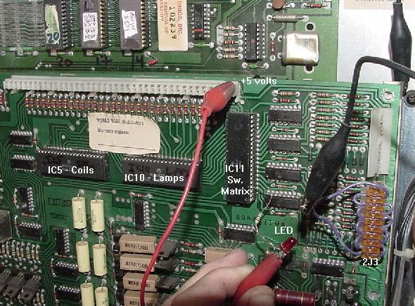
Using Leon's test chip with the CPU and Driver board mounted in the game. Note
power supply fuses F1 (H.V.), F2 (coils) and F3 (lamps) are removed. +5 volts is
gotten for the tester LED at pin 1 of the interconnector. Driver board PIA IC5
(coils) is at the left, PIA IC10 (lamps) is in the middle, and PIA IC11 (switches)
is on the right. Notice the custom connector at 2J3 to short the switch matrix row
pins all to ground.
|
Again use the "tester LED" with the non-resistor lead connected to +5 volts,
and check the three PIA chips (mounted left to right on the driver board) -
IC5 (solenoids), IC10 (lamp matrix) and IC11 (switch
matrix), with the resistor lead of the tester LED. Check:
- PIA Pins 2-17 high then low (tester LED on and off), alternating on and off every second*.
- IC18 PIA Pins 19,39** high then low (tester LED on and off), alternating every second
(note these pins may not pulse).
- PIA Pins 26 to 33 are the data lines, and should be pulsing (use
a logic probe for this).
- PIA Pin 34 (reset) should be high.
* NOTE: When testing the IC11 pins 2-9 on the driver board (switch matrix),
a slight modification is needed to the driver board. On driver board
connector 2J3, short to ground *all* these connector pins
when testing IC11 pins 2-9 (PIA outputs PA0 to PA7). If this is not
done, IC11 pins 2-9 will not alternate on and off.
** Leon's chip also tests pins 19 and 39 on the PIAs. These are the CA2 and CB2
ports. Each 6821 has these two "special" ports (in addition to the eight ports
at PA0-PA7/PB0-PB7), which are used mostly for the Special Solenoids. If CA2 or CB2
is labeled as a "STx" port on the schematics, that means it controls a Special
solenoid when the game is in diagnostics, and these may not alternate on and off
(as the PA/PB ports do). Keep that in mind.
If any pin 2-17 are not alternating high then low, then
the PIA is bad. Remove the bad PIA chip, install a socket
and a new PIA 6821 chip. Also check
the interconnector pin 37 (blanking), as this should be high (LED on).
CPU board Locked Up with Driver Board Installed and Leon's Test Chip.
This is fairly common, and indicates one (or more!) of the PIAs have
failed. Even with Leon's test EPROM installed, it is fairly common
to have the driver board lock-up the CPU.
The most common PIA to lock up the CPU is driver board IC11, the switch matrix PIA.
Go ahead and desolder this chip, install a socket and a new 6821 chip.
The other two PIAs (solenoids and lamp matrix) can also fail, but they
do not tend to lock up the CPU board like a failed switch matrix IC11
chip. If the CPU board is still locked up after replacing IC11,
replace the driver board IC5 PIA (solenods) next.
Still locked up, finally replace the driver board IC10 PIA (lamp matrix).
In real life, the driver board's IC5 solenoid PIA may fail the most of the PIAs,
due to locked on coils
from shorted driver transistors. These shorted driver transistors can take out
the 7408 chip which drive them, and the IC5 solenoid PIA which drives the 7408.
But the driver board IC11 switch
matrix PIA is a close second in failure.
The driver board's switch matrix IC11 PIA, like the solenoid PIA,
only has a single TTL chip in front of it
for protection. So when someone shorts a solenoid or lamp voltage across the
switch wiring under the playfield, it usually takes out the 7406 or 4049
chips and the IC11 switch matrix PIA.
The driver board lamp matrix PIA rarely seems to fail, in comparison
to the switch matrix and solenoid PIAs.
Check the Blanking Signal on the CPU/Driver Boards.
Blanking Signal Introduction.
Most people will be asking,
"what is this Williams 'Blanking' Signal I hear so much about?"
The blanking signal is a flag between the CPU and driver board that says,
"Hey, the driver board PIAs chips are OK, the CPU ROM chips
are good, we're booted and running, all is A-OK".
So once the CPU ROM program thinks everything is good, it
sets the blanking signal high. This in turn allows the rest
of the game to "come to life". If the blanking signal never
goes high, the solenoid, CPU control lamps, and/or the score displays
won't work. The game will seem like it's trying to boot up
and function, but the blanking signal keeps the game from
coming to life at the last second. This is a protection
device to prevent the game from destroying itself if the CPU
thinks there is a problem.
The reason the Blanking signal gets so much (bad) press,
is if the game is not working, the Blanking gets blamed (though
in most cases, no blanking signal is the symptom, not the cause
of the problems). So again,
it should be stated right up front that most "blanking signal problems"
are not related to the blanking circuit itself! If the blanking signal
never goes "high", usually the problem is
bad chip sockets (Scanbe), bad PIAs, or bad 40 pin interconnector. But if all
the tests have checked out Ok with Leon's test chip, and the blanking
signal is still low, there is good reason to suspect the blanking circuit itself.
As Mark says, "blanking will always be zero (low) unless the
board has successfully booted with the game ROMs".
The purpose of the blanking signal is to shut down the displays,
solenoids and lamps in case of a software or hardware problem.
This prevents possible damage to the game if there is a problem.
The symptoms of a low blanking signal are dead score displays
and no CPU controlled lamps (which also
happens to be the symptoms of almost every other
MPU board problem!) If the board seems to be
booting with the game ROMs and it passes the self
test (both LEDs flash and then go off), check the
Blanking signal at pin 37 of the
interconnector; It should be 4 to 5 volts.
As R.Cole describes the blanking is a hardware generated signal where
all of the PIA outputs on the driver board are ANDed together (that is,
PIAx must be high AND PIAy must be high, etc, to get a final high blanking signal).
When the blanking signal is low, all of the controls to the transistors are low
and hence there are no switched lights and no solenoids (this is a protection
trigger so coils/lights don't burn up if there a problem with a PIA).
With the blanking system low, the displays do not turn on either.
When the CPU board's blanking circuit sees driver board PIAs ANDed together,
the PIA outputs are enabled and the blanking signal is high, allowing the
solenoids and lamp matrix to work.
Since the blanking signal is ANDed with the
output of the driver board PIAs, the driver transistors won't ground (energize)
a coil unless a high signal comes from both the PIA and the blanking
circuit. That is, both the blanking signal and the PIA output must be high
to fire a coil. So how can the blanking signal cause all the coils or lamps
to lock-on at power on? A high blanking signal will not cause the solenoids or
lamps to lock-on, as this is normal in-game operation. However if the
blanking signal is lost from the CPU to driver board through a broken 40 pin inter-connector,
this will cause the solenoids and/or lamps to latch 'on'.
Because now the blanking input to the AND gates will be left floating
(undefined) with no clear logic level. You can easily correct
this by making sure that 40 pin interconnector has been replaced.
In addition, all PIAs come out of reset at power-on with their ports configured as
inputs, until reprogrammed by the CPU. If the CPU board does not run because it's
faulty, and the blanking signal is missing on the driver board, you have a mix that can
cause the AND gates to possibly switch to an 'on' state (documented by Clive). This can cause
all the game's coils and lamps to lock on.
Blanking Components.
Mark explains
the blanking signal is controlled by a timer circuit
(a 556 in System 3-6 games and a 555 in System 7
games). When the game software is running properly, port
PA2 on PIA IC18 pin4 is pulsed every .8 msec. This pulse is
fed to IC7 inverter 7404 pins 5/6, and into the blanking circuit. This resets the
timer after the signal from PA2 goes high and then low
again. If the timer "goes off", blanking is stays low.
As long as the timer is reset before it
triggers, blanking will remain high. If the game program
locks up or the CPU stops running, then the
timer will expire, setting blanking low. The key is the
signal from the PIA going from High to Low, the
transition is what resets the timer. If the port sticks
high or low, then blanking will be set low (no
transitions are occurring). Also I have seen the blanking signal
on a scope "look right" from the PIA port PA2 to the 7404, but the game
won't boot. This is because the PIA was bad, and the blanking signal was
not the right waveform.
Blanking and Leon's Test ROM.
Note Leon's test ROM may still
work even if the blanking signal circuit is not working and is low,
so this signal needs to be checked before installing the boards in a game
(Leon's test chip does alternate high and low the Blanking signal about
once a second, just like the PIA outputs).
The symptom of a low blanking signal can be the
CPU/driver board work fine on the bench with Leon's test chip,
but is dead when installed in a game with the game ROM and Flipper ROMs.
Usually the problem is the blanking signal is high on the CPU board, but is low
on the driver board (which makes the game appear "dead"). This is
caused by a bad 40 pin interconnector between the CPU and driver boards.
Also keep in mind if
testing the boards using Leon's test chip, the blanking signal
may or may not be present. This is due to the fact that the test chip
pulses port PA2 on IC18 pin4 only about twice a second, which may or may not
be fast enough to reset the timer circuit. Because of this,
disregard the blanking signal with Leon's test chip installed.
Unfortunately the Blanking signal can only be tested once the
boardset is running properly with the game ROMs installed.
That said though, I have found the Leon test chip helpful as
it does pulse once a second the blanking signal from PIA ic18 pin4. This goes
to ic7 pin 5, which should also be pulsing once a second. Then
this 7404 inverts the signal and puts it out to pin6 (which should
be pulsing once a second, but in opposite order of pin5 and with a
very slightly longer high tone.) Then the
signal goes to the top leg of cap C31 (upper left of CPU board.)
The lower leg of cap c31 and middle leg of Q5 should be about 3.2 volts.
The lower leg of Q5 should be moving once a second between 3.7 and 3.5 volts.
The upper leg of Q5 should show no voltage (ground). The TP4 (blanking)
will pulse once a second between 0 and 1 volt (hence Leon's chip
doesn't give a good blanking signal indicator as 1 volt isn't exactly a
high signal.)
Likely Blanking Signal Problem Parts.
Remember the likely cause for a low blanking signal (other than the things
mentioned above) is a bad CPU board PIA at IC18, bad inverter chip 7404 at IC7,
timer chip failure (556 for sys3-6, 555 for sys7) at IC23,
a bad C31 (.05 mfd) capacitor, or a bad Q5 transistor (2N4403).
The Q5 transistor tests easily with a DMM, and replace cap C31. Note the
signal goes through cap C31 so if the cap is bad, the blanking won't get to
transistor Q5. Also or some reason 7404 chips
are prone to failure. And the timer chip is small and cheap
to replace. So start with those thing. But don't forget that 40 pin PIA at IC18,
as they like to fail too.
In system3 and system4, the 556 timer is also used to generate the IRQ signal,
so suspect a bad C31 or Q5 first. On System 6/7, the timer chip (556 for sys6 or
555 for sys7) is only used for blanking.
On sys6-7 look at the outputs of IC25 (4020 1ms timer) with a scope or logic probe. If the
interrupt signal is not being generated at the correct speed, then
555/556 timer IC23 will not generate the required "pulse".
Testing for the Blanking Signal.
To test the blanking signal is pretty simple. Power
the CPU/driver board up on the bench with the game ROMs installed,
and put a DMM on pin 37 (fourth
pin from the left) of the
driver board's interconnector.
After the CPU board boots,
this should read at 4 to 5 volts DC. If it does not, the blanking
signal has not gone "high". If using Leon's test ROM, the blanking
signal will instead alternate high and low once every second.
To make sure the problem is not the interconnector, check the blanking
signal on the CPU board at connector 1J3 pin 4. If the blanking signal
is Ok at 1J3 pin 4 but not on the driver board's interconnector pin 37,
the interconnector is bad.
If the blanking signal is missing at 1J3 pin 4 also,
the interconnector is probably Ok, but the
parts generating the blanking signal are bad.
If the problem is the blanking circuit itself (all the rest of
of the CPU/Driver board is really Ok), with the game ROMs installed
the CPU LEDs will act "normally". That is, at power on
a system3-system6 game will flash both LEDs on then off.
On system7, the "0" will flash and
turn off. But the score displays and CPU lamps won't come on. If
the self-test switch is then pressed on the CPU board, the CPU memory
test will be run (system3-6, both LEDs should flash twice if
everything tests correctly). If all this checks out (and all fuses
for the score displays and CPU lamps are good), there is a
good chance everything is Ok except for the Blanking circuit itself.
A Cheat to Determine if the Problem is the Blanking Circuit.
As a "cheat" to get the driver board to "wake up",
+5 volts can be temporarily jumped to pin 37 of the interconnector.
If all of Leon's tests passed, and jumpering pin 37 to +5 volts
lets the game come on, chances are good the actual blanking
circuit itself is bad.
Left: Blanking signal on a system4 CPU board coming out of capacitor C32,
at the cap's left leg.
Right: Blanking signal going into capacitor C32, at the cap's right leg.
Pictures by Jerry.
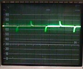
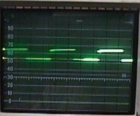
|
Checking the Blanking Circuit Components.
If the blanking signal is low,
but Leon's program is running fine
and passes all the tests, suspect the blanking circuit.
But remember, the blanking circuit really can not be checked with
Leon's test ROM installed (as described above, with Leon's test chip
the blanking signal could be high or low). The game ROMs must
be installed to check the blanking signal.
First check
capacitor C32 on system3-6 CPU boards or C84 on system7 (.047 mfd, 50 volts).
The picture above shows an oscilliscope connected to each leg
of capacitor C32. The picture on the left is the signal going out
of the left lead of capacitor C32.
If this signal is missing then the blanking signal will not be high
on interconnector pin 37 or CPU connector 1J3 pin 4.
The picture on the right shows the signal going into the
the right leg of capacitor C32 (or C84 on system7).
If this input signal is missing then the problem is most likely chip IC7 (7404,
all system3-7 CPU boards).
Now back up and start at PIA IC18 port PA2 pin4. There should be about 2.5 volts DC of
waveform there. This goes to IC7 inverter 7404 pin5, and out of pin6. The signal should still be a good
2.5 volt waveform. I have seen a bad PIA where the signal looked good coming into the 7404,
but was flat coming out of the 7404. This would make you think the 7404 was the problem,
but in fact it was the PIA.
Now the signal goes to the timer chip.
In system3 and system4 boards, the 556 chip is used to generate the
Blanking and IRQ signals. On System 6 boards the 556 is only used for blanking.
On system 7 the 555 chip is also only used for the blanking signal.
Next check transistor Q5 (or Q1 on system7), a 2N4403, which can be tested
with a DMM set to the diode function. If both transistor Q5 (or Q1 on sys7) and cap C32
(or C84 on sys7) test good, as does chip IC7, next suspect the timing chip IC23
(a 556 chip on system3-6, or a 555 chip on system7).
I have found the Leon test chip somewhat helpful with blanking as
it does pulse once a second the blanking signal from PIA ic18 pin4. This goes
to ic7 pin 5, which should also be pulsing once a second. Then
this 7404 inverts the signal and puts it out to pin6 (which should
be pulsing once a second, but in opposite order of pin5 and with a
very slightly longer high tone.) Then the
signal goes to the top leg of cap C31 (upper left of CPU board.)
The lower leg of cap c31 and middle leg of Q5 should be about 3.2 volts.
The lower leg of Q5 should be moving once a second between 3.7 and 3.5 volts.
The upper leg of Q5 should show no voltage (ground). The TP4 (blanking)
will pulse once a second between 0 and 1 volt (hence Leon's chip
doesn't give a good blanking signal indicator as 1 volt isn't exactly a
high signal.)
As R.Cole describes,
the IC23 timer in the blanking circuit is set up as a resetable one-shot. The signal from
one of the PIAs resets the timer periodically. This is a watchdog type of circuit.
If the CPU locks up and the IC23 timer chip does not get reset,
then the blanking signal goes low and the switched lights and the solenoids are disabled.
There is one transistor in the blanking circuit (Q5 or Q1 on system7) and if shorted,
it can take out a capacitor C32 (C84 on sys7) in the process.
The blanking LED installed on the driver board's pin 37
interconnector to an LED, to a 150 ohm resistor, to ground.
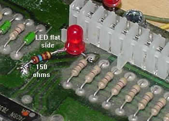
|
Add a Blanking Signal LED.
This is a neat trick that Jerry came up with. He adds a blanking signal
LED to the driver board on his test fixture. This way the
blanking signal can be seen at
a quick glance. Certainly this isn't needed on every driver board, but
if you have one working "test" driver board, this is a neat addition.
Personally, I add this LED to every driver board (but hey, I like LEDs
and I'm easily amused).
To add the LED, just solder the interconnector's
pin 37 to the round side lead of an LED. Then connect the flat side
lead of the LED to a 150 ohm 1/4 watt resistor. Finally connect the other
side of the resistor to ground (the big fat trace going around the
edge of the driver board).
Now when the CPU board is powered on, the
LED will be off for just a moment, and then turn on and stay on, indicating
a good blanking signal is getting to the driver board from the CPU.
Leon's Test Chip is Working with the CPU/Driver board: Testing the Driver Board.
Now that driver board *and* CPU board are seemingly working together,
it's time to try some other driver board tests using Leon's test chip.
For all these tests, the "tester LED" is required!
Note since the PIA chips are already tested, the tests below
try and check the system from the PIA to the driver board connector.
In many situations, it is just easier to test the transistors and
support chips without power, just using a DMM. This is described in
Lamp matrix,
switch matrix, and
Non-work/Locked on coils
sections. But to be complete, the tests below can be used too.
Switch Matrix "Drive" (Column) Test (Connector 2J2).
Connect the tester LED's non-resistor lead to +5 volts.
Using the resistor lead of the tester LED,
touch each pin on driver board connector 2J2.
The tester LED should alternate on and off, in unison with the
blinking LEDs on the CPU board. If the alternating signal is missing
on any connector 2J2 pin, yet all the IC11 PIA signals are present,
IC17 or IC18 (7406) on the driver board has failed.
To verify which input chip IC17 or IC18 is bad, check the input
pins of these chips. Put the resistor lead of the tester LED on
IC17 and IC18 pins 1,5,9,13. These pins feed from the PIA (which
was tested earlier). Now put the resistor lead of the tester LED
on IC17 and IC18 pins 2,6,8,12. If these output pins are not alternating
but the input pins are alternating, the chip in question is bad.
Leon Testing Switch Matrix "Inputs" (Row) Test (2J3).
To test the switch rows, the pins at connector 2J3 will
need to be grounded.
To test row 1, ground pin 9 of 2J3. Using the Tester LED with
the non-resistor end connected to +5 volts,
put the resistor end of the Tester LED on the switch matrix PIA
IC11 pin 2. The LED should be flashing. Move the ground to 2J3 pin 8,
and check for a flash at IC11 pin 3.
Continue moving the ground down a pin on connector 2J3, and moving
the tester LED up a pin on IC11. The LED should flash should at each step.
If it doesn't, the PIA IC11 is probably bad.
Lamp Matrix Strobe (Column) Test (Connector 2J5).
To test the lamp matrix columns, power has to be applied to any pin of
driver board connector 2J4.
Normally this is +18 volts, but for our test, +5 volts will work
fine. Using an alligator test clip, connect +5 volts
(TP9 on system6/7 CPU boards, or interconnector pin 1 on the far right)
to any pin of connector 2J4 on the driver board.
In addition, the connectors at both 2J5 and 2J7 need to be
attached from the game. If testing "on the bench", an alternative
method can be used (see below).
Now connect the tester LED's non-resistor lead to +5 volts.
Using the resistor lead of the tester LED,
touch each pin of driver board connector 2J5.
The tester LED should alternate on and off, in unison with the
blinking LEDs on the CPU board.
If the CPU/driver board combo is on a bench with no access to
the playfield connectors 2J5 and 2J7, another method must be used.
With the tester LED's non-resistor end connected to +5 volts,
touch the tester LED's resistor end to the left most leg of
each transistor Q62, Q64, Q66, Q68, Q70, Q72, Q74 and Q76 (the
small transistors along the right edge of the driver board).
The tester LED should alternate on and off, in unison with the
blinking LEDs on the CPU board (the tester LED will not work
directly on connector 2J5 without the playfield connectors 2J5/2J7).
If the alternating signal is missing,
yet all the IC10 lamp PIA signals are present,
check the inputs of IC13 or IC14 (7408) on the driver board (pins
1,2,4,5,9,10,12,13 of IC13 and IC14). If there is no input signal,
there is a bad TIP42 (Q63,Q65,Q67,Q69, Q71,Q73,Q75,Q77)
driver transistor or 2N6472 (Q62,64,66,68, 70,72,74,76) pre-driver transistor
feeding the chip. Then check the output signals
of IC13 and IC14 (pins 3,6,8,11). If
the input signal is turning on and off, but there is no output signal,
the chip is bad. Note the output signal from the chip may be very short.
Lamp Matrix Row Test (Connector 2J7).
This test also requires +5 volts power to any pin of driver board connector 2J4.
Normally this is +18 volts, but for our test, +5 volts will work
fine. Using an alligator test clip, connect +5 volts
(TP9 on system6/7 CPU board, or interconnector pin 1 on the far right)
to any pin of driver board connector 2J4.
In addition, this test also requires a ground connection
to any pin of driver board connector 2J6
(if the boards are installed in the
game, just have the game connector attached at 2J6).
Once power and ground are applied to the lamp matrix,
now connect the tester LED's non-resistor lead to +5 volts.
Using the resistor lead of the tester LED,
probe on each pin of driver board connector 2J7.
The tester LED should alternate on and off, in unison with the
blinking LEDs on the CPU board.
If the alternating signal is missing
on any connector 2J7 pin, yet all the IC10 PIA signals are present,
check the outputs of IC19 or IC12 (7406) on the driver board (pins
2,4,6,8,10,12 of IC19 and pins 2,4 of IC12). If there is no output signal,
the chip is bad. If the output is good, there is a
bad 2N5060, 2N6427 or 2N6122 transistor.
Solenoid Driver Test (Connectors 2J9,2J11).
No additional power hook-up are required for this test.
Connect the tester LED's non-resistor lead to +5 volts.
Using the resistor lead of the tester LED,
test each pin of
driver board connectors 2J9 and 2J11.
The tester LED should alternate on and off, in unison with the
blinking LEDs on the CPU board.
If the alternating signal is missing
on any connector pin of 2J9 or 2J11, yet all the IC5 PIA signals are present,
check the output of chips IC1,IC2,IC3,IC4 (7408 pins 1,2,4,5,9,10,12,13).
if any are missing, the chip as failed. If all alternating signal is present,
there is a failed predriver 2N4401
(Q14,Q16,Q18,Q20,Q22, Q24,Q26,Q28,Q30,Q32, Q34,Q36,Q38,Q40,Q42,Q44)
or driver TIP120/TIP102 transistor
(Q15,Q17,Q19,Q21,Q23, Q25,Q27,Q29,Q31,Q33,Q35, Q37,Q39,Q41,Q43,Q45).
Special Solenoids Trigger Test (Connector 2J12).
A modified test for this is needed to test the
switch triggered special solenoids.
This test requires a ground connection
to any pin of driver board connector 2J10
(if the boards are installed in the
game, just have the game connector attached at 2J10).
Also selected connector 2J13 (switch inputs) pins will need
to be grounded for this test. Then
connect the tester LED's non-resistor lead to +5 volts.
Using the resistor lead of the tester LED,
touch connector 2J12 pins specified below (note that
2J12 pin 2 is not tested, as this is the flipper coil ground return).
- Tester LED to 2J12 pin 3, and ground to 2J13 pin 2 (IC6 pin 12).
- Tester LED to 2J12 pin 4, and ground to 2J13 pin 3 (IC6 pin 9).
- Tester LED to 2J12 pin 6, and ground to 2J13 pin 4 (IC6 pin 5),
- Tester LED to 2J12 pin 7, and ground to 2J13 pin 5 (IC6 pin 2).
- Tester LED to 2J12 pin 8, and ground to 2J13 pin 8 (IC7 pin 12).
- Tester LED to 2J12 pin 9, and ground to 2J13 pin 9 (IC7 pin 9).
The tester LED should flash on and off for each 2J12 pin listed above.
If the tester LED is locked on or off, the ground connection to
connector 2J13 can be moved backwards through the circuit to find
the faulty component (the tester LED should *not* be moved). For example:
- Move ground from 2J13 pin 2 (IC6 pin 12) to IC6 pin 11.
- Move ground from 2J13 pin 3 (IC6 pin 9) to IC6 pin 8.
- Move ground from 2J13 pin 4 (IC6 pin 5) to IC6 pin 6.
- Move ground from 2J13 pin 5 (IC6 pin 2) to IC6 pin 3.
- Move ground from 2J13 pin 8 (IC7 pin 12) to IC7 pin 11.
- Move ground from 2J13 pin 9 (IC7 pin 9) to IC7 pin 8.
If the tester LED now flashes when ground is moved from 2J13 to the appropriate
IC6/IC7 pin, then IC6 or IC7 is bad.
If the tester LED is still not flashing, move ground again through the
circuit:
- Move ground from IC6 pin 11 (IC8 pin 5) to IC8 pin 4.
- Move ground from IC6 pin 8 (IC8 pin 12) to IC8 pin 13.
- Move ground from IC6 pin 6 (IC8 pin 9) to IC8 pin 10.
- Move ground from IC6 pin 3 (IC9 pin 2) to IC9 pin 1.
- Move ground from IC7 pin 11 (IC9 pin 5) to IC9 pin 4.
- Move ground from IC7 pin 8 (IC9 pin 12) to IC9 pin 13.
Again if the tester LED now flashes when ground is moved from IC6/IC7
to the appropriate IC8/IC9 pin, then IC8 or IC9 is bad.
If the tester LED is still not flashing,
a 2N4401 pre-driver (Q1,Q3,Q5,Q7,Q9,Q11) or TIP120/102 driver transistor
(Q2,Q4,Q6,Q8,Q10,Q12) has failed.
Summary of Driver Board Tests.
Remember, the "tester LED" should always be used for the driver
board test. A logic probe will not always give a good indication
of the circuit's condition.
The Built-In Williams Firmware Diagnostics.
The flipper ROMs also contain some built-in factory diagnostics.
For this to work, the
standard game ROM and Flipper ROMs must be installed, and the driver board
connected to the CPU board.
System3 to System6 CPU boards have two red LEDs (Light Emitting Diodes)
which provide some limited diagnostic information. If the CPU board successfully
boots, both LEDs will blink together once, and then turn off. If one of both
LEDs locks on, this is an indication of a problem. But the main problem
with this diagnostic system is this: the game must have booted correctly,
and be in attract mode, for any LED indication to be valid!
Now how much sense does that make? If the CPU board boots, and the
game goes into game over (attract) mode, chances are pretty good
that the CPU board is working! (This is unlike Bally's 1977 to 1985
system, where the LED flashes as the game boots, testing each major
CPU component in the process, and giving a big clue as to what it
thinks is wrong).
What most people miss is this: if either or both LEDs
(or the 7-segment LED on system7) are locked on
at power-up, the CPU board has not booted properly. Basically it's
the software contained in the EPROMs that turns off the LEDs. If
the LEDs never turn off, the software is probably not executing.
There there is a problem,
and it must be fixed before the LEDs can be trusted for any diagnostic help.
And if the game comes up in "audit" mode, and the CPU batteries are good,
the IC19 CMOS 5101 RAM is bad. So why do we need the Williams' diagnostics?
If there is a problem with the Flipper ROMs or game ROM,
at power-up both LEDs will flicker, then
both LEDs will come back on and stay on.
Compare this to powering-on the CPU board,
and both LEDs come on and stay on with no flicker (this
indicates a locked-up CPU board).
On system3 to system6 CPU boards,
when the board starts correctly, the LEDs flash once and then go out.
Now push the CPU board's diagnostic
switch SW1 (the lower button) once. IMPORTANT: on System6/7 games, the
coin door must be open (memory protect switch open).
If all diagnostics pass, both LEDs will flash briefly
*twice*, and turn off. The game will not return to attract mode.
Turn the game off, and repeat the test three or
four times. If the same result is received
every time, the results of the test can be considered "valid".
If different results are seen, NONE of the results can be trusted!
If different results are seen between multiple tests, the first
thing to suspect is chip IC19 (5101 CMOS RAM), and then
chips IC13/IC16 (6810 or 2114 RAM).
If any of these are in sockets, suspect the socket too.
What the diagnostic software is trying to do is this:
The Flipper ROM software reads a few
bits from IC20 (the Flipper ROM), and then attempts to write that to IC13/IC16
(6810 or 2114 RAM) and IC19 (5101 RAM). If the
results don't equal what's in the Flipper ROM,
then the LED locks on. 99.9% of the time the problem
is IC19 (the 5101). The two static 6810 or 2114 RAMs (IC13/IC16) are
rarely bad. While flipper ROM IC20 could be bad, the game usually
won't boot for the user to even run the diagnostic test if thats the case.
System3 to System6 CPU Board Factory LED Diagnostics.
Once the CPU/driver board is booted and the game is in attract mode,
press the CPU board's SW1 diagnostic switch (the lower switch).
Remember on System6 games, the coin door needs to be open.
If the SW1 diagnostic switch causes both LEDs to flash twice and go out,
the CPU board is probably OK. It might still have display problems,
if that happens check CPU board PIA IC18 (score display PIA).
Most other components are OK if two flashes are seen. After the
two flashes, the game will need to be turned off and on to exit
the test (and go back to attract mode).
If either or both LEDs remain lit, the test program has found a problem:
- Upper LED on: ROM failure. Check EPROM & sockets IC17/IC20/IC14.
If the top LED remains lit, this indicates there was a read problem
at CPU chips IC14, IC17 or IC20 (the EPROMs).
But since the diagnostic program is located in IC17/IC20, it is highly unlikely that
the game would have even booted if there was a problem with either of these.
The game ROM at IC14 could be suspect if the game booted and the SW1 test
was performed, and this LED stays on.
- Lower LED on: RAM 6810 failure. Check IC13/IC16, sockets and IC8.
- Both LEDs on (after flashing): CMOS RAM 5101 (IC19) failure. Also check IC12/IC7.
Remember on System6 games the coin door must be open when this test is run or
both LEDs will turn on due to the memory protect circuit.
But if both LEDs remain lit (after flashing), this is an indication that the 5101 has failed.
This is a somewhat silly test, because if your game powered up in "audits" mode,
and couldn't go into attract mode by cycling the power switch quickly,
the IC19 RAM can be assumed dead.
- Both LEDs flash twice and go off: RAM/ROM self test passed.
If there are still problems, most likely the driver board or inter-board connector
are at fault.
Try the test three or four times. If the same result is received
every time, the results of the test can be considered "valid".
If different results are seen, NONE of the results can be trusted!
Again, if different results are seen between multiple tests, the first
thing to suspect are chip IC19 (5101 CMOS RAM), and chips IC13/IC16 (6810 RAM).
If any of these are in sockets, suspect the socket too.
System 7 CPU Board Factory LED Diagnostics.
The System7 diagnostic tests and codes aren't quite as dumb
and unreliable as the above mentioned System3-6 codes. But all the
same rules apply here. That is, the CPU board must boot correctly
to trust the diagnostic codes. IMPORTANT: the coin door *must* be
open to run the diagnostic test! (That is, the memory protection
switch must be open.)
With the coin door open, switch SW1 (the lower button on the CPU board)
can be pressed once to run the diagnostic test.
The LED display should show "zero" for a second.
If everything is Ok, the display will go blank for
another second, and the game will return to attract mode.
If there is a problem, the error code will display the
error number in the LED, and the number will stay displayed.
The game will *not* go to attract mode.
The System7 test diagnostic LED values are listed below*:
- 0 - Test Passed, everything OK.
- 1 - IC13 RAM 2114 fault or IC20 ROM bad
(test reads from IC20 and writes to IC13).
- 2 - IC16 RAM 2114 fault.
- 3 - IC17 ROM 2 fault.
- 4 - IC17 ROM 2 fault (a strange test duplication?)
- 5 - IC20 ROM 1 fault, or coin door closed, or Memory protect circuit fault.
- 6 - IC14 Game ROM 1 fault.
- 7 - IC26 Game ROM 0 fault.
- 8 - IC19 CMOS 5101 RAM, or coin door closed, or Memory protect circuit fault.
- 9 - IC19 CMOS 5101 RAM, or coin door closed, or Memory protect circuit fault.
Again, try the test three or four times. If the same result is received
every time, the results of the test can be considered "valid".
If different results are seen, NONE of the results can be trusted!
Again, if different results are seen between multiple tests, the first
thing to suspect are chip IC19 (5101 CMOS RAM), and chips IC13/IC16 (2114 RAM).
If any of these are in sockets, suspect the socket too.
* NOTE: If using System3 to System6 firmware EPROMs in a System7 CPU board,
the LED diagnostic display will not function as described above! System3 to
System6 software does not support the seven segment LED that is used on
the System7 CPU board. In this case, if CPU board diagnostic switch SW1
is pressed, the upper segments of the LED will flash a "u" twice if the test
passes (the "u" is essentially the equivalent of both LEDs on a
system3-6 CPU board flashing).
The game will not return to attract mode. Not much can be diagnosed
here, unless System7 EPROMs are installed back into the system7 CPU board, and
the test rerun. It's not a bad idea to install the two LEDs and two resistors
back into the system7 CPU board, as described above.
Some Real Life System7 Test Numbers.
Unfortunately, because the system7 tests are not fully
reliable, here's a list of some "real life" problems seen
with the Williams test numbers:
- 1 or 2 - Chips IC32, IC12, IC31 potentially bad (Memory Protect Circuit).
Rarely is it a IC13/IC16 (2114) chip problem.
- 8 - Bad IC36. (note Williams Test Rom ignores this chip).
Game Roms use IC36 and if bad, will lock up CPU.
- 8 - Coils pull in when game is turned on. This can be caused by a bad IC23 (555 Timer).
- 9 - Check IC7 pin 13, must be High. (Chip U7 could be grounding the signal.)
If running system7 software,
what the System7 diagnostic software is trying to do is almost
the same as the System3 to System6 software. But since there's
a seven segment LED, the output report is more specific to the
exact problem chip suspected.
The Flipper ROM software reads a few
bits from IC20 (the Flipper ROM), and then attempts to write that to IC13/IC16
(2114 RAM) and IC19 (5101 RAM). If the
results don't equal what's in the Flipper ROM,
then the LED locks on. 99.9% of the time the problem
is IC19 (the 5101). The two static 2114 RAMs (IC13/IC16) are
rarely bad. While flipper ROM IC20 could be bad, the game usually
won't boot for the user to even run the diagnostic test if that's the case.
Other Notes:
System7 codes 3, 4, 6 and 7: These error codes usually indicate a bad ROM chip.
As described in the ROM chip section and
socket sections,
the original black ROM chips should have been replaced with new EPROMs.
If one of these ROM chips is bad, replacing all of the CPU ROMs chips too.
If both LEDs remains on after flashing (System7 codes 8 and 9),
often the memory protect circuit could also be bad (this circuit prevents
adjustments from being changed unless the coin door is open).
But chances are really good the problem is really the IC19 RAM 5101 is bad.
Williams Test EPROMs.
Using a Williams test EPROM can help simplify start up problems, and
maybe help the CPU board boot. But even with this chip, the LED fault
indications are again not valid unless the CPU board boots first.
The bottom line is don't use this Williams test EPROM with a boot-up
problem, use Leon's test EPROM instead. But the Williams test EPROM and
instructions can be downloaded by clicking
here.
Andre Boot's Test ROM.
Andre Boot has also created a test ROM for system3 to system7 boardsets.
His works differently than Leons, and is a bit more "automatic".
You can download his test ROM, disassembly 6802 code, and instructions
here.
Andre's test ROM causes the LEDS on the MPU to flash five times for a stanalone MPU board,
and nine times if the driverboard is connected.
Every flash is an IC test. Here are the LED flash codes:
- 0 flashes : MPU lockup
- 1 flash: IC 13 MC6810 RAM DEFECT
- 2 flashes: IC 16 MC6810 RAM DEFECT
- 3 flashes: IC 19 CMOS RAM DEFECT
- 4 flashes: IC 18 PIA I DEFECT
- 5 flashes: IC 11 PIA 2 DEFECT
- 6 flashes: IC 10 PIA 3 DEFECT
- 7 flashes: IC 5 PIA 4 DEFECT
- 8 flashes: INTERRUPT CIRCUIT DEFECT (Need to make a jumper at 1J4 connector for this test)
- 9 flashes: All good for system3-6 boards. IC 36 PIA 5 DEFECT for system7 boards.
- 10 flashes: All good for system7 board.
Andre Boot Test ROM Installation Instructions.
- Turn off power.
- Disconnect connector: 1J3, 1J4, 1J5, 1J6, 1J7, (for
level 7 boarden also 1J8). remove ROM 2.
- Burn testROM.716 to a 2716 EPROM.
A 2732 or 2532 version is available for system7 boards using the file
testROM.732. Installed the testROM in CPU board at socket IC17.
- For level 7 boards only: Jumper W23, W12, W9.
- Power on.
With Driver board connected it should flash nine times (ten times for system7).
With driver board disconnected is should flash five times.
All Done with the CPU/Driver Board Tests!
Now that all the tests have successfully run with Leon's test chip
and William's built-in tests,
the CPU and driver boards can be installed into the game and tested
(make sure the game ROM and Flipper ROM software is installed in the
CPU board). Also be sure to remove power supply board fuses F2 and F3
(to remove power from
the solenoids and lamp matrix for the initial power-up).
It should be noted that just because everything checked out with
Leon's test EPROM and Williams' built-in tests, does not 100% guarentee the CPU/driver boards
will work in the game! It's a pretty good chance they will, but
these tests are not perfect, and can overlook some problems.
Just keep that in mind.
If the game boots and works, turn
the power off and add fuse F3 (lamp matrix) first. Power back on
and see if the game's attract mode lamps are working. If successful,
power off and add fuse F2 (solenoids). Power back on and hopefully
no coils lock on. If any coil(s) do lock on, check the driver board
for shorted solenoid driver transistors.
* Return to the Pin Fix-It Index
* Go to Part One System3-7 Repair Guide
* Go to Part Three System3-7 Repair Guide
|

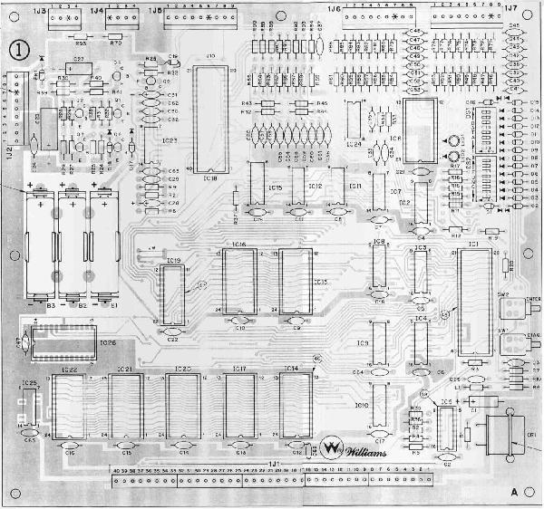
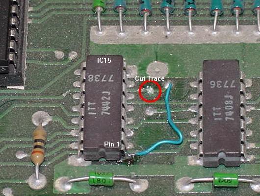
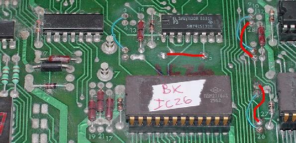
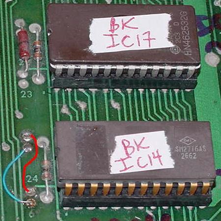
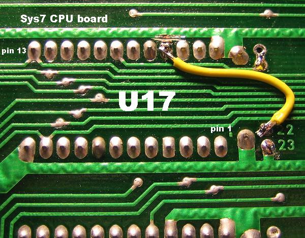
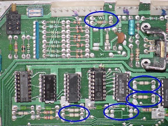
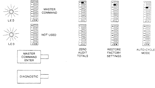
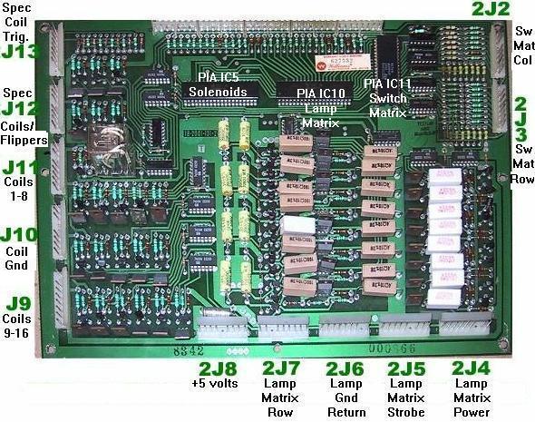
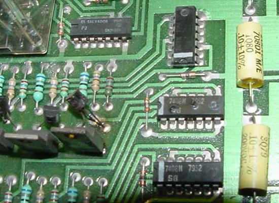
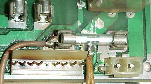
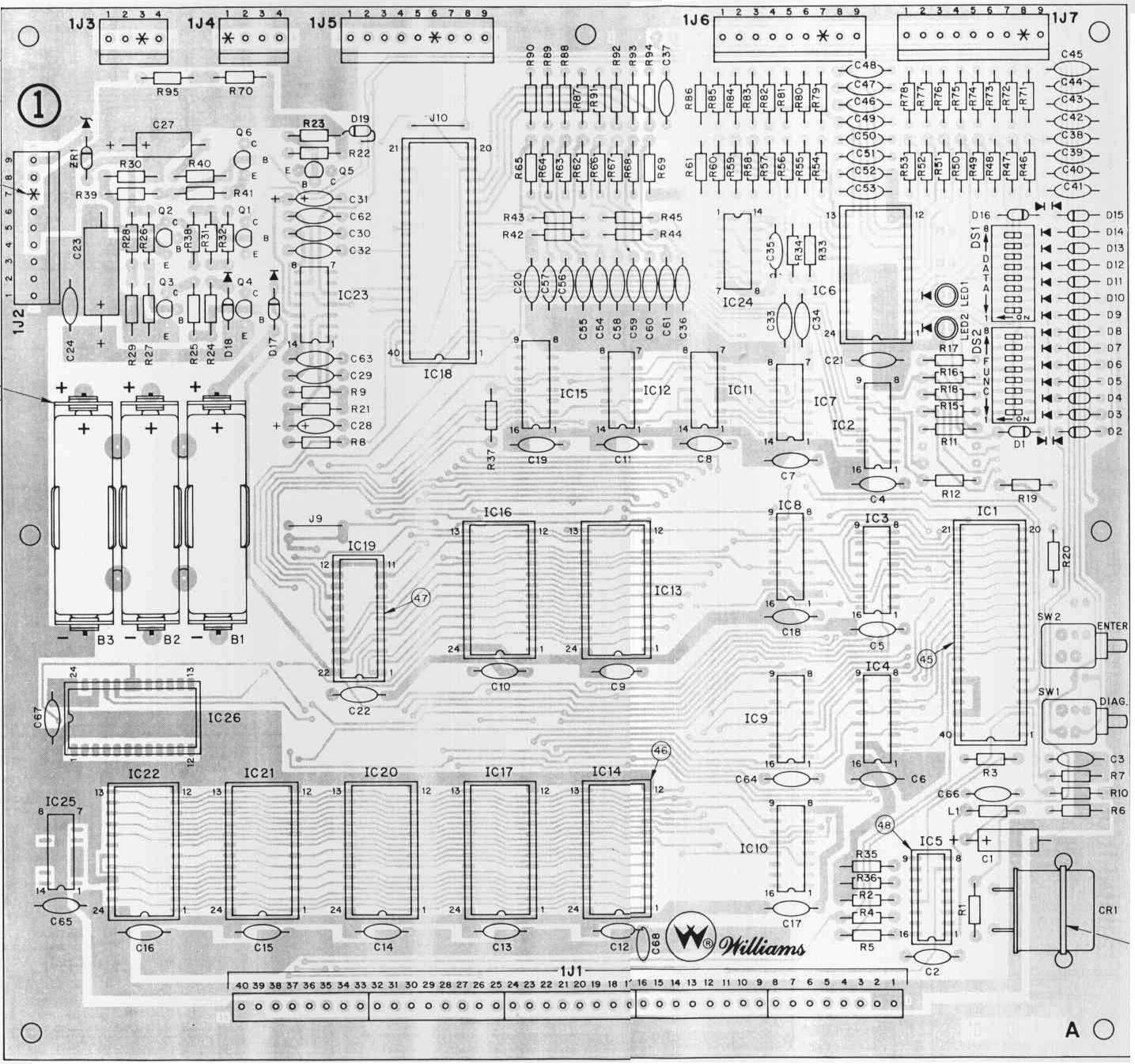
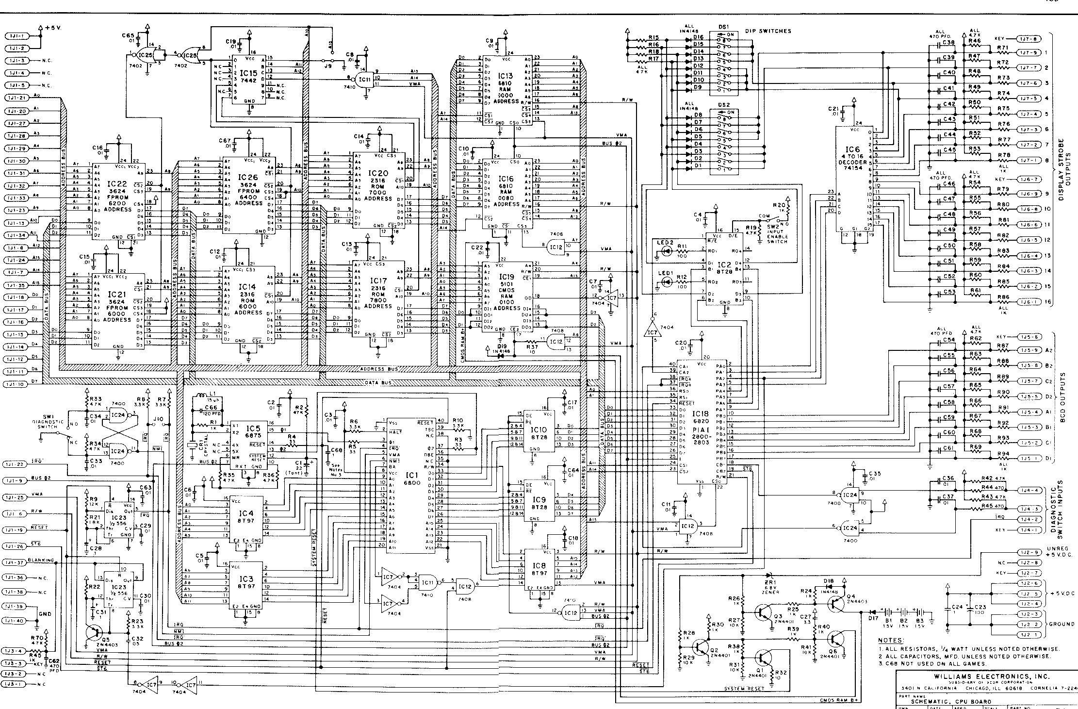
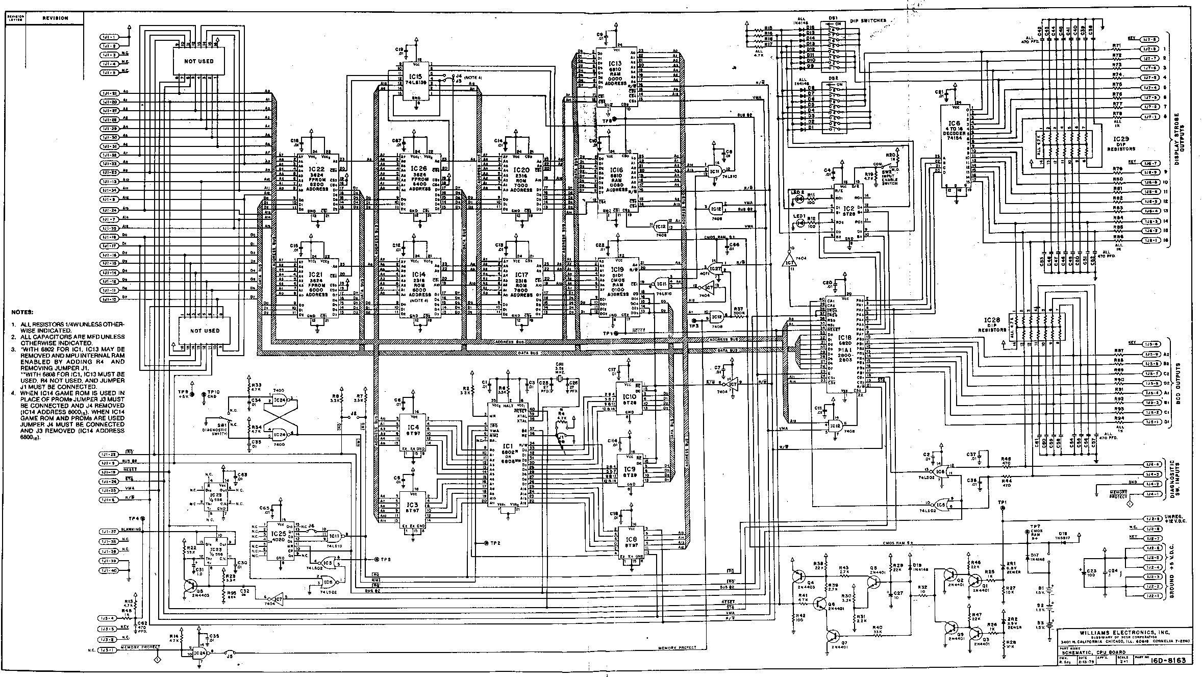