and Conversion from Snow Blower Engine to Mini Bike Engine format.
I buy and collect minibikes. 04/10/25. Email: cfh@provide.net
Table of Contents Chapters.
- Introduction (a Flat Head for your 1970s Mini Bike
- Finding a Good Snowblower Donor
- Dating a Tecumseh Engine
- Snowblower Engine a Good Minibike Engine?
- PTO Output Shaft and Extended Cam shaft
- Ignition - Points/Condenser or Electronic, and flywheel material
- Snow Parts Removal
- PART NUMBERS often needed
- CONNECTING ROD, Governor, Side cover replacement)
- Engine Color Off and Back On
- POINTS Condenser replacement, Flywheel removal, Kill Switch, Lighting
- RINGS Check and Replacement (Honing/Boring)
- CAM, Valve Lapping, Valve Springs
- CRANKSHAFT
- FLYWHEEL and Blower Housings
- Torque Wrench Numbers and Engine Specs
- Dipstick, Oil Plug, Spark Plug
- Minibike Throttle Assembly and Gas line installation
- Pull Start Mechanism Maintanence
- First Time Starting the Engine
- Carburetor (stock style)
- Slant Carb Intakes
- Carburetor Alternatives (slide carbs)
- PTO drilling for clutch
- Exhaust ideas
- Measuring RPM
- Decals for the Blower Housing
- Conclusion
- FLYWHEEL and Blower Housings
- 1974 Tecumseh Engine Specs
- 1977 Tecumseh Engine Specs
- 1983 Tecumseh Engine Specs.
- 1987 Tecumseh Engine Specs
- 1992 Tecumseh Engine Specs
- 1994 Tecumseh Engine Specs
- 1997 Tecumseh Engine Specs
- 2004 Tecumseh Engine Specs.
- 1998 Tecumseh Technicians L-head Service Manual.
- 2000 Tecumseh Quick Reference Troubleshooting.
- 2004 Tecumseh Basic Service and Troubleshooting.
- 2005 Tecumseh Parts Guide.
- 2010 Tecumseh Parts Guide.
- 2002 Tecumseh Craftsmen cross reference.
- 1970 Minibike Guide Tecumseh Performance rebuild doc.
- 1972 Minicycle magazine Tecumseh AH817mb review.
- Speedway mini bike information
- Rupp mini bike information
- Fox mini bike information
- MTD mini bike information
Other useful technical material:
1. A Tecumseh Flat Head for Your 1970s Minibike - Introduction.
-
Say you have a vintage 1970s mini bike and you want a proper
flat head motor for it. How would someone go about doing that?
First, let's talk a bit about minibike engine history...
In late 1969, Briggs and Stratton decided they would no longer sell their flat head motors to minibike makers. They just didn't want to be associcated with minibikes (probably more legal reasons than anything.) But regardless, this really opened the door for Tecumseh to supply motors. And just about all the mini bike makers took Tecumseh up on this, and utilized their engines for minibikes during the 1970s.
But the problem with 1970s motors is time, and kids, and mini bikes. After all, who rode mini bikes during the 1970s... crazy kids! And they probably didn't treat these motors very well. That's why when you see a 1970s vintage minibike for sale today, often it is missing the motor.

-
Yes there are modern motor replacements. The Harbor Freight $100 "Predator 212"
motor has put a good number of old minibikes back on the road. But
the "look" of the 212 motor is completely different than the old school
Tecumseh flathead. For example the cylinder
isn't vertical, it's more horizontal. In fact, there's really nothing
that looks even similar on a Predator 212 to a classic Tecumseh motor.
And if you're going for that vintage look, the modern Predator 212 style overhead value
motor just isn't going to cut it.
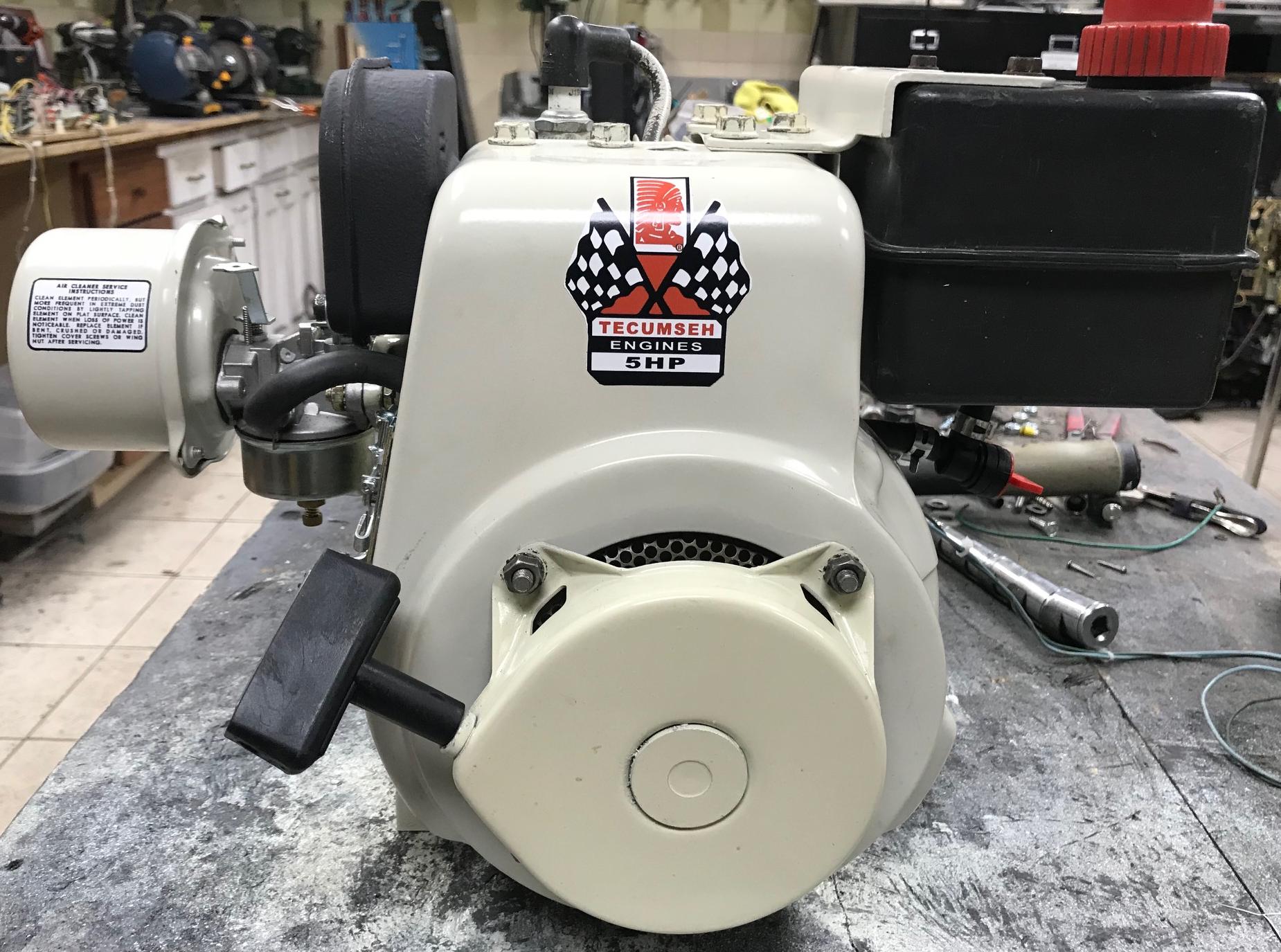
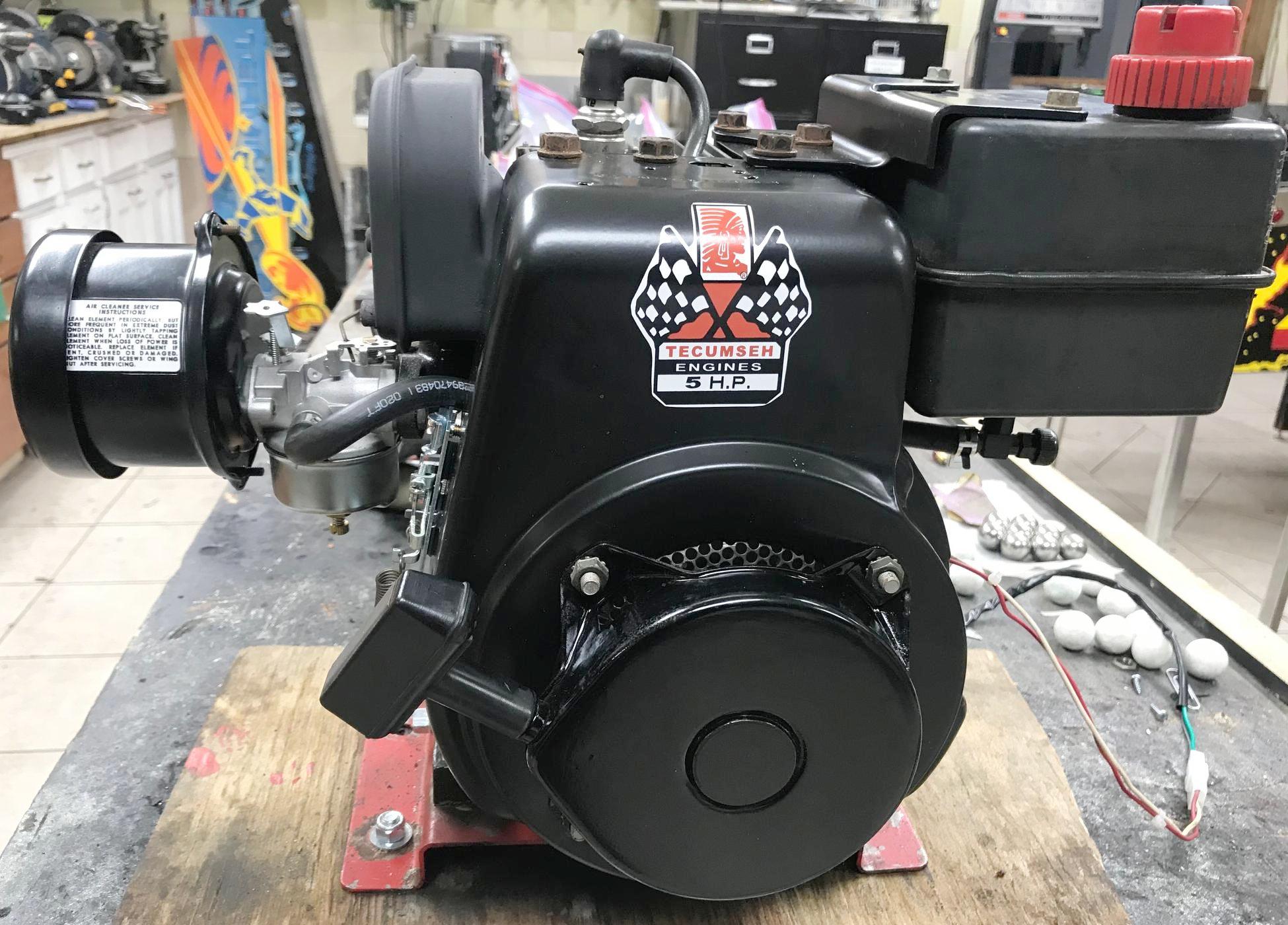
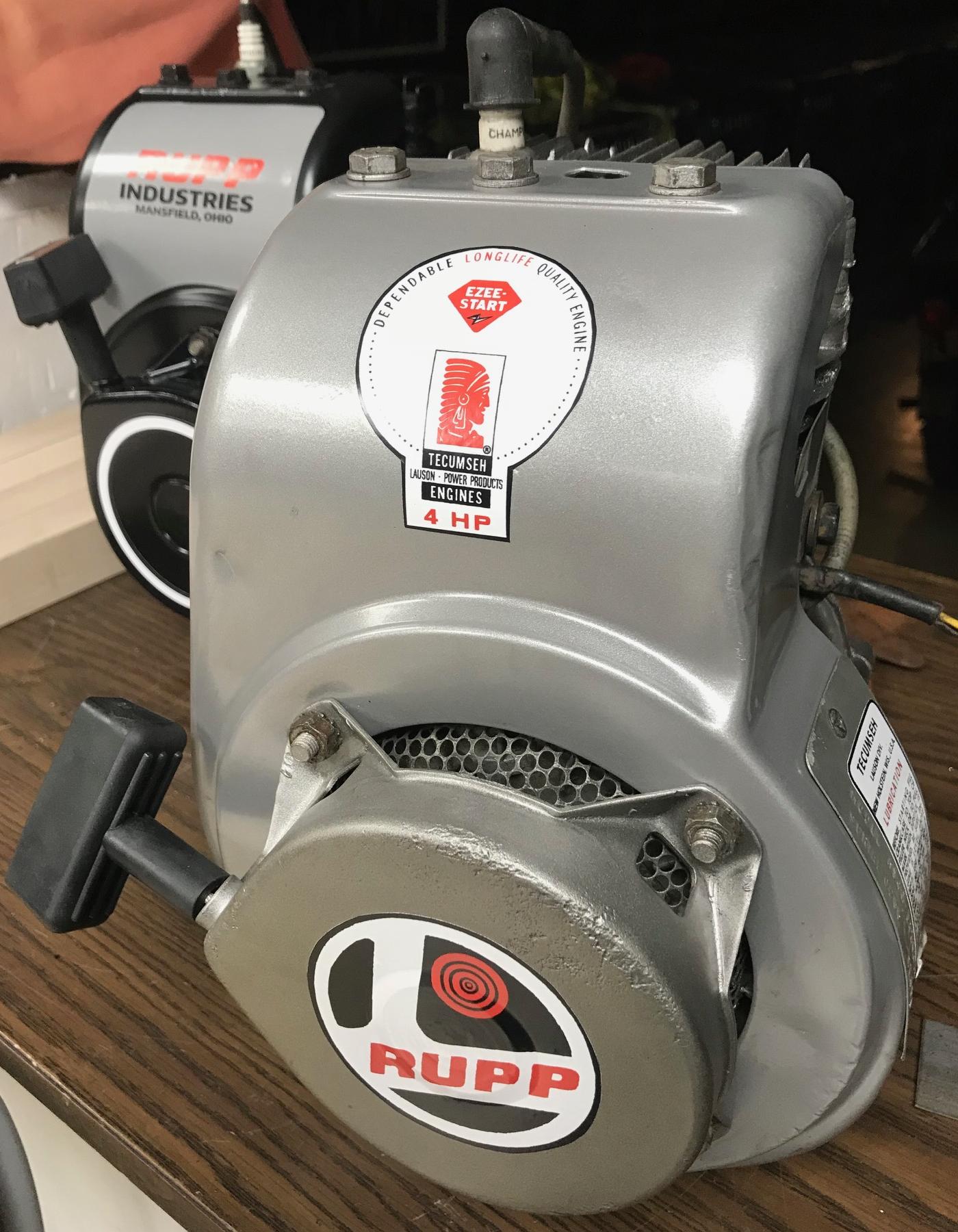
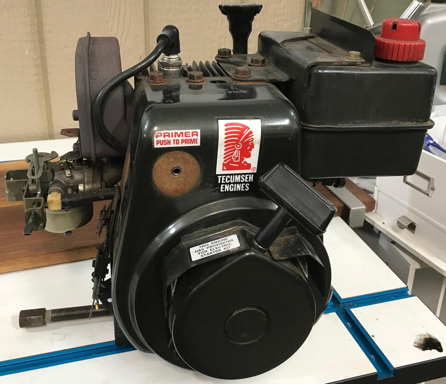
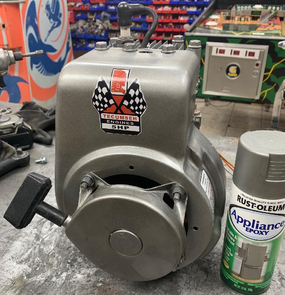
Or if you prefer in black... a minibike ready Tecumseh HS50. This particular motor
came off a 1970s Arien snowblower.
-
If your 1970s Tecumseh minibike motor, which is now 40+ years old and
abused by every 10 year kid in the neighborhood, is dead... How do you get
a decent motor to restore your vintage minibike? Well the short
answer is, Snowblowers!
I guess it depends where you live, but here in the midwest, old snowblowers are pretty common (and cheap.) And generally speaking, at least here in the midwest, a 20 or 30 or 40 year old snowblower motor tends to be pretty low usage. Why is that? Well they were only used during snow times (no dirt or high temperatures). And in the midwest (I'm in Michigan), we don't tend to get a lot of snow (maybe 30 inches a year.) So these old snowblower flathead Tecumseh HS50 engines are great donors for a vintage minibike.
That said though, snowblower flathead Tecumseh engines need some work to make them minibike-ready. And that's what we are going to discuss in this document. Obviously you need some tools to do this, and some general mechanical knowledge. I will assume you have these things! Also you'll need some parts. Most is available from Ebay or some of the online small motor warehouses. Also note some abbreviations like SBH (short block horizontal), BB (ball bearing), HS (horizontal small frame), BCR (bump compression release), MCR (mechanical compression release).
The Famous Tecumseh HS40 Engine.
We should talk about the Tecumseh HS40 motor. It was the mainstay of
minibike motors during the 1970s. The Tecumseh 4hp HS40 was introduced in 1968,
but really did not get traction with minibike manufacturers until about 1970.
At that point, the large frame H50 motor was out of favor (due to it's
extremely wide body format), and the much narrower HS40 just fit better
in the wave of mini-cycle style bikes made in the 1970s (like say the
Rupp Roadster, etc.) Since there was no small format 5hp motor (until 1972
when the HS50 was introduced), the HS40 really was the go-to motor for
a great number of minibike/minicycle makers.
-
The early October 1967 to 1970 Tecumseh HS40 motors had some small differences like
a mechanical compression release (MCR) camshaft (as the motor starts, the
compression release swings out of the way). The placement of the intake was nearest the cam gear,
so the mechanical release could be used on the intake valve. Into 1971 they dropped the
MCR (mechanical compression release) cam and only offered a BCR (bump compression release)
on the exhaust lobe. Hence the early HS40 engines' cam had a huge intake lobe
on it, and they compensated with a shorter lifter so they had to clearance
the crankshaft for it to fit. After the changed to a bump compression
release (BCR) that was a permanent bump on the cam shaft for the exhaust.
Frankly the BCR style can suck power out of an engine.
Sure it helps with starting, but it doesn't go away like MCR after the
engine starts. The bump can easily be ground off the cam though.
-
With that all said, you will see a lot of references to the HS40 motor
in this document. Not because I recommend getting a HS40 motor from a
snowblower... if you're doing that you're better off with an HS50
snowblower motor. But a lot of people like to rebuild original HS40
minibike motors from 1969-1975 for their originality. Also if you
have a minibike that has lights (like say a Rupp Roadster), an original
HS40 motor with an alternator is really the way to use lights (I have yet to
see a snowblower with an HS50 motor and an alternator!) Because of this,
you will see a lot of HS40 references in this document. (Though MTD did
make minibikes 1972-1975 with original HS50 motors and provisions for lights.)
But again, if you need a motor (you have nothing), and you want a Tecumseh flathead for your vintage 1970s minibike, converting a snowblower HS50 motor to minibike format is really the way to go!
2. Finding a Good Snowblower Donor.
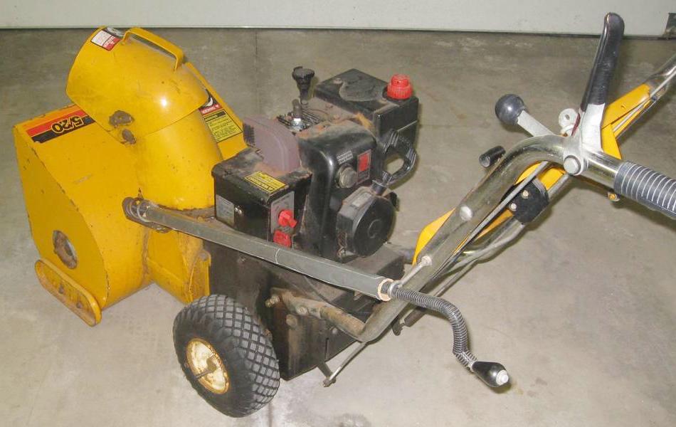
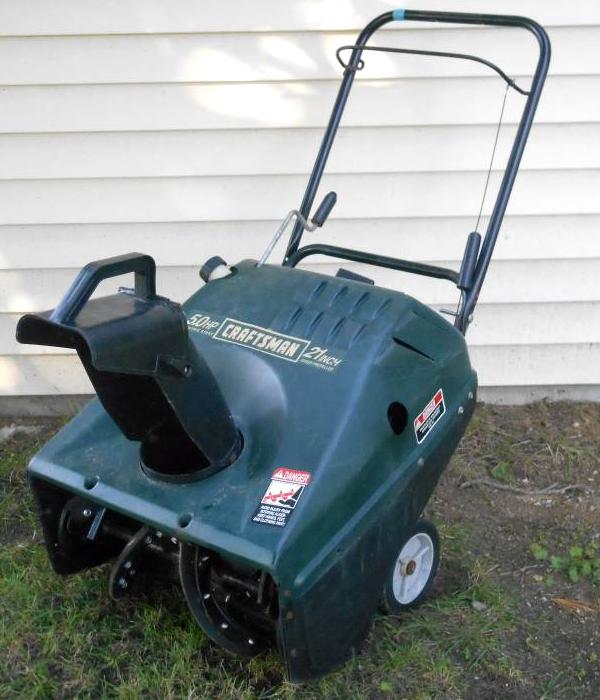
Finding a good used (old) snowblower (if you're in a snow area), should be pretty easy. Craigslist (especially during the summer) should net a good donor snowblower. Ideally you want a Tecumseh HS50 (5hp) motor (introduced in 1972) on a nasty looking snowblower, but a Tecumseh HS40 (4hp) motors work great too (they were introduced in 1968.) This is usually pretty easy to identify from the snowblower model number. For example, a Toro 521 is a 21" wide snowblower with a 5hp motor. Just make sure it's a Tecumseh flat head (HS50 or HSSK50 or LH195), and you're probably golden. Likewise if you find a 4hp Tecumseh, the same model designations apply. That is, an Arien 420 will be a 4hp motor on a 20" wide snowblower.
-
Note because I'm no longer 10 years old and 100 pounds, I try to get
5hp flathead motors. But frankly the Tecumseh HS40 motor (4hp) works
pretty darn well too. One thing I would say though, don't get a Tecumseh H50
engine. The H50, used before Tecumseh introduced the HS50 in 1972, is
too wide of a format for many minibike applications. Though some minibikes
did originally use the H50 in the 1968-1972 time frame, especially since Tecumseh
discounted the H50 because of the HS50 release in 1972. But the HS frame size is just so much
nicer of a motor to use in nearly every minibike wanting a flathead.
-
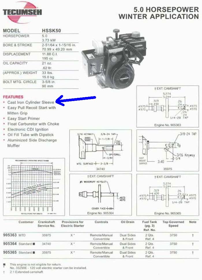
Also do not discount the newer HSSK50 or LH195 Tecumseh snow blower motors. Though the
pull start looks slightly different, theses winter application motors are
very good. So good infact, some have a cast iron cylinder (opposed to
aluminum.) These are darn good motors.
In the 2000s Tecumseh came out with the LH195 motor. Basically it's a replacement for the HS50 with some small modifications. They advertise this motor as 5.5hp (instead of the HSSK50's 5hp rating.) This happened because they dialed in the porting, manifold, and cam a bit, allowing for a bit more horsepower. In particular the LH195sa and the LH198sp both came out around 2006. The "P" means "power up", and hence the increase in stats from 5hp to 5.5hp. The LH195 cam is part #37040. Late production models of the LH195 will have a *plastic* cam. Obviously you don't want that! The plastic cam needs lighter duty valve springs too. So if you're good at looking at valve springs through a removed breather assembly, you can tell if it's a metal or plastic cam. If you get an LH195 with a metal cam, that's a great motor. It uses all the same parts as an HSSK50 (or late model HS50) engine (aside from the cam and lifters, be it metal or plastic.)
Generally I avoid 3hp and 3.5hp (Tecumseh H30 and H35) engines. Often they have a 5/8" PTO shaft. And they are usually "side poppers" (exhaust on the PTO side of the engine). Side exhaust will really limit your exhaust options, as the common "Taylor" minibike exhausts don't exist for side poppers. Also personally I don't like exhaust blowing on my left leg! And 3hp and 3.5hp are just too whimpy. If you're going through all this trouble to re-do a motor, it's better to have a 4hp or (better yet) 5hp motor as your starting point. Note they did use side popper engines on a few minibikes in the 1970s, but for 98% of all mini bikes, rear exhaust engines were the norm. It's the same amount of work to restore a H30 motor as it is an HS50 engine. So why not get the best starting point with the more power.
-
Note you do not want the "combo" snowblower plastic models. Generally
these will have a tapered PTO output shaft, which won't work on
a minibike. Avoid these models unless they are dirt cheap (or you
can see the PTO shaft, and make sure it's not tapered.) You can convert
a tapered shaft motor to a fixed width, but it's more work and expense.
Hence you're better off not getting a "plastic" snowblower (unless it's
dirt cheap or free!)
Do we care if the motor runs? Heck no! In fact, I would say a non-running snowblower is probably an advantage, as the snowblower will be cheaper. We are going to rebuild the motor anyway. I mean if it runs that's great. But it's not necessary.
Tecumseh made flathead motors until 2006 (Tecumseh went out of business in late 2008.) The newer 1998 five HP and later style flathead motors are not labeled as HS50 but are HSSK50. Then a little later the HSSK50 became the LH195 models. The 1988 and later models all have a newer style "cyclone" or "pull lite" pull starter (introduced early 1988). They are great flathead motors too, though they don't have quite the same look as the old style "four leg" pull start motors. If you get a snowblower that is an HSSK50 motor (or LH195 which was called 5.5hp), don't turn it down. They are great flathead motors, and all the info here applies to them too. Also some HSSK50 motors have a cast iron cylinder sleeve (instead of aluminum) for increased life.
The newer flathead cyclone motors do have some advantages. For the most part, they are really an older HS50, but with some modifications to make them emit less hydrocarbons. That doesn't effect their power. In fact, because they are newer, chances are pretty good that they will have lower time (usage). Also they won't be a "points and condenser" motor, but will have electronic (solid state CDI) ignition... which frankly is a really nice feature (one less thing you'll have to worry about, and less parts to buy/adjust/maintain.) After August 1984 the HS50 "E" series (for non-snowblower engines) and since April 1985 the HS50 "F" series (snowblower engines) used CDI ignition.
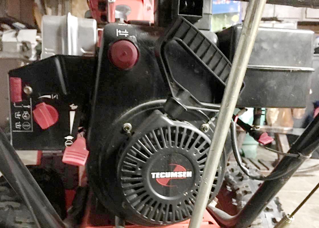
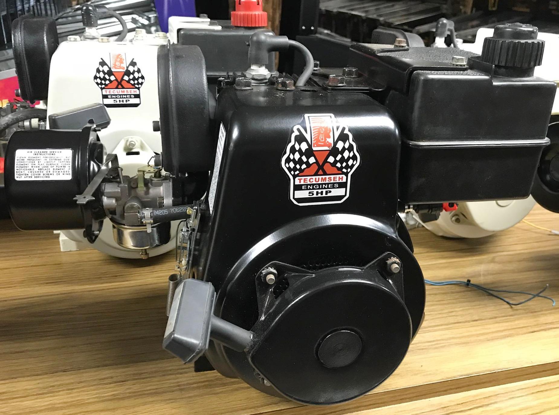
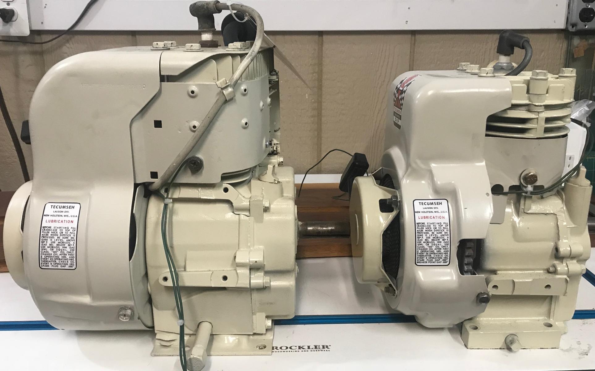
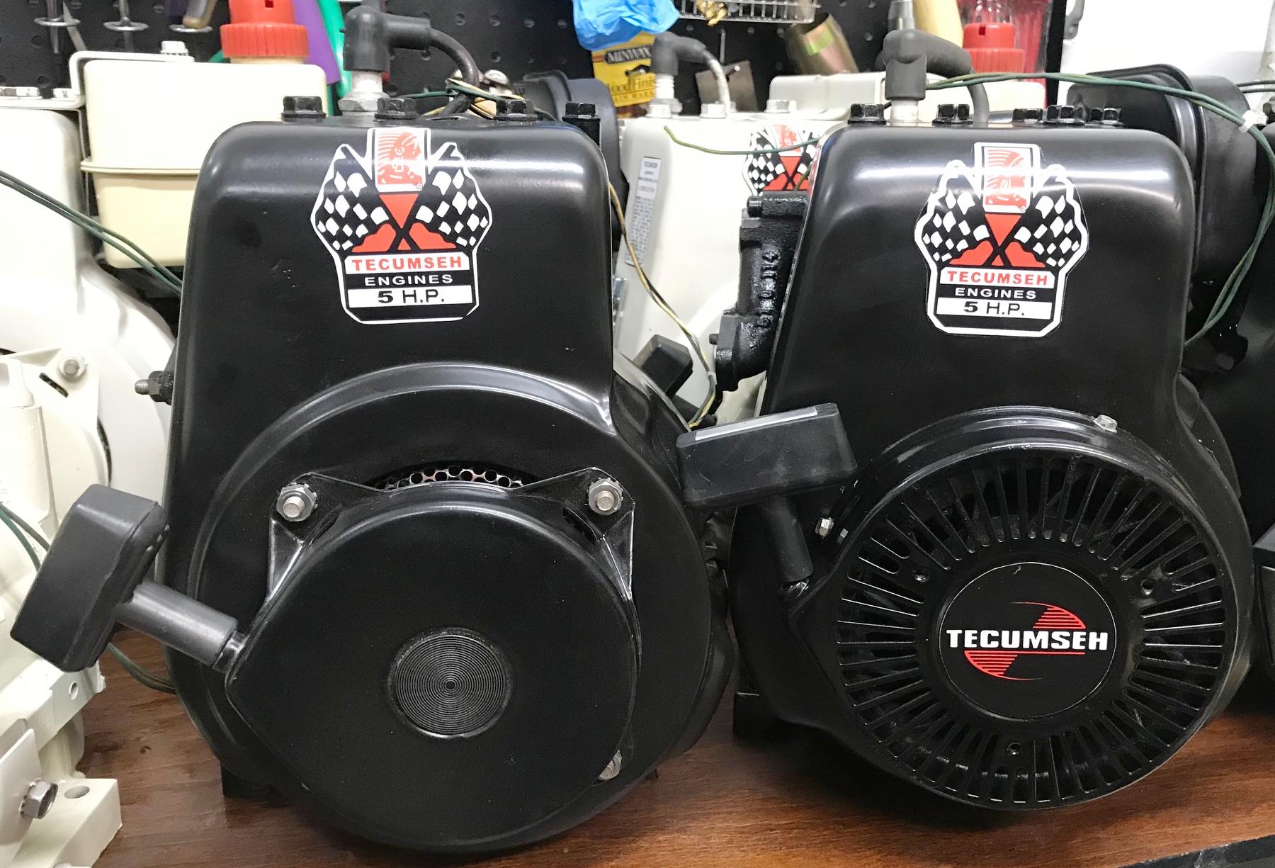
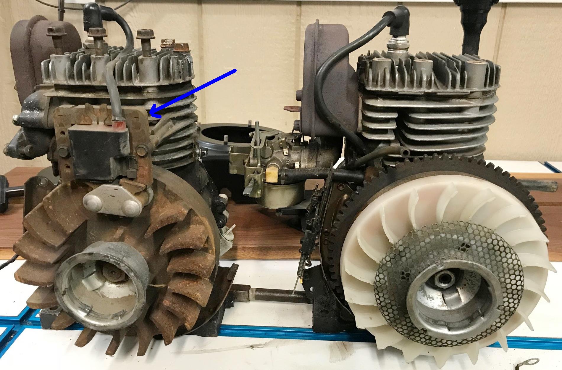
Here's two converted snowblower Tecumseh 5hp engines. The one on the left is an
"old school" 4-leg pull start 1982 model HS50. The one on the right is a 2001 Tecumseh HSSK50
motor with the "cyclone" pull start. Note after the conversion to minibike format they
don't tend to look that much different. And both work great on a mini bike. And if you
really want, the old style 4-leg pull start blower housing/starter for the HS50 will fit right
on the newer HSSK50 engines. This gives the 'old look', but on a newer motor.
-
If you can't find a number identifying which model a motor may be, you
can always remove the head and measure the bore. Or look at the
orientation of the exhaust/intake ports:
- HS50 intake port "D" shaped, on the left as facing the ports.
- HS40 intake port "O" shaped, on the left as facing the ports.
- H30/H35 intake port on right as facing the ports.
- H35 exhaust port often on the PTO side of the engine (but not always, application dependant.) These motors are nicknamed "side popper" because the exhaust is on the side of the motor. Only a few mini bike makers used this style of motor, so generally I avoid these motors for mini bike applications.
- AH520 = 5.2ci or 85cc
- HSK600 (or AH600) = 6ci or 98cc
- AH817mb = 8.17ci (134cc) 5hp, designed for a mini bike.
- HSK845 = 4.5hp
- HSK850 = 5hp (139cc)
- HSK870 = 7hp
Don't forget Sears (Craftsmen) snowblowers either! Though Sears uses their own "143" number (instead of a Tecumseh number), most Sears/Craftsmen snowblower engines were made by Tecumseh. You can cross reference the 143 craftsmen number to figure out what the Tecumseh number may be (and the size/hp of the motor.) A link to that cross reference is at the top of this document.
After you have found your donor snowblower, remove the motor. It should be pretty obvious what is needed to be done for this task. The most difficult task will be getting the pully off the PTO output shaft. I personally often use a 3-leg flywheel puller for this task. Not necessary but it helps a lot.
What about the 2 cycle Tecumseh engines?
Tecumseh made some decent 2 cycle engines for snowblowers that can work
on a mini bike. Mounting them may be a bit of work, and also make
sure the engine has a 3/4" diameter PTO shaft.
And use a good quality synthetic oil that is blended with fuel stabilizer/gas
at 50:1 and it will run clean.
They can work decently in a mini bike, at least the 5hp models (don't
use the smaller versions, not enough power.) Here's the breakdown:
3. Dating a Tecumseh Engine.
-
Tecumseh used a pretty consistent method to dating their motors.
The only problem with their method is the lack of a decade in the
serial number/year number. But based on other information, you can
generally tell what decade the motor was made. Some things to think
about on the HS40 and HS50 include:
- Balloon style blower housing decal: up to 1970
- Flags style blower housing decal: 1970-1978
- Tecumseh Decal Retangle style: 1978 and newer
- Small metal tag with numbers, bolted to fins on side of the cylinder: pre-1975. But sometimes this is seen with short/long block numbers into the 1990s.
- Blower Housing numbers on the side of housing, on a two rivet tag: pre-1974.
- Blower Housing numbers stamped into metal on top near spark plug, 1973 and later.
- Sticker with model/serial number on side of blower housing (bar code): 1995 and later.
- Blower Housing Shape: a rounded blower housing part# 30655 (rounded as the metal bends towards the spark plug): pre-1974.
- Blower Housing Shape: starting about 1972-1974 most horizontal shaft motors changed to a square top blower housing. (HS50 from 1972, and HS40 in 1973.)
- Blower Housings consistent between models H30,H35,HS40,HS50 (part# 33663 square top style): November 1974 and later.
- Blower Housing hump removed at the 4 leg recoil (to accommodate the CDI ignition coil): late 1984 (around "E" or "F" series on HS50).
- Four leg pull start: up to 1987.
- Cyclone "pull lite" style pull start: 1987 and later.
- Giant mitten pull start handle (used on both starter styles): 1984 and later on many Snow King engine models.
- Plastic gas tank: 1970 transitioned from metal to plastic (some exceptions.)
- Spark plug wire routed around cylinder to PTO side: pre-1977
- Spark plug wire routed on top of head (head fins modified): 1977
- Points/Condenser ignition: pre July 1984.
- CDI solidstate ignition: summer 1984 and newer.
- 11/16" flywheel nut (old style taper): 1980 and earlier (models A,B,C on HS50 have old 16 degree taper).
- 3/4" flywheel nut (new style taper 10 degrees): late 1980 and newer (models D and later).
- 1995: HS50 changes exhaust valve to be smaller.
- Motor block painted: pre-1994.
- Naked (no paint) motor block: 1994 and newer.
- Alloy flywheel: up to 1974.
- Cast iron flywheel: 1974 and later.
- HS50 designation discontinued: 1998
- HS40 model production discontinued: 1997
- H40 and LH195 models started: 1998
Note in 1997 the HS40 motor goes out of production, and is replaced in 1998 with the H40 engine. The H40 is really an H35 motor in disguise, as the H40 bore/stroke is the H35 size of 2.5" x 1.938" (not the HS40 bore/stroke of 2.625" x 1.938"). This means the H40 is only 156cc, compared to the HS40 which is 172cc. So why did they call it four horsepower? If it's like the LH195, it gets more horsepower because it has a higher lift cam. The piston on the H40 uses the same top two rings as an H35 (oil ring not interchangeable.) My suggestion is to avoid this motor. That is, get a HS40 or HS50 instead. Also in 1998 the LH195 comes about, which is a replacement for the discontinued HS50. The LH195 has a bore/stroke of 2.795" x 1.938" (identical to the 1990s HS50.) The LH195sa and the LH198sp both came out around 2006. The "P" in the "SP" means "Power up", and hence the increase in stats on this motor from 5hp to 5.5hp at 3750rpm.
The numbers on the blower housing is what identifies the motor type and it's date. The first set of numbers are the motor type like "HS50", for example. The second set of numbers are the actually motor spec number. This is important information when ordering parts. The third set of numbers is the serial number. But really it's the manufacture date. The first number is the last digit of year. The next three numbers are the day (from 001 to 365). Sometimes there's a letter after this number, which gives further info like shift/plant, etc.
The problem with the Tecumseh date scheme is that no decade is provide in the date code. Hence the above bullet points help figure out exactly when a particular motor was made.
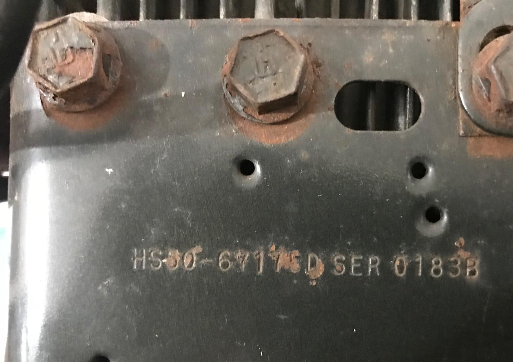
Dating a Tecumseh motor: On the top of mid-1970s Tecumseh motors should be impressed
numbers, as shown here. This is a HS50 spec# 67175d. Newer motors (like 1990s till 2008)
used a sticker with a bar code identifying the motor number.
In the picture below you can see on the left "HS50", which
is the model/size of the motor. If you want to know the year,
look at the number after "SER" (the third set of numbers). In the example above the numbers are "0183b".
The "0" is the last digit of the year, and the "183" is the day of the year
(from 001 to 365) that the motor was made, and the "B" is the factory the
motor was made. So the above motor was made
on July 2, 1980. So how did we know it was 1980 and not 1990? Well the decade can
be a bit tricky, but for the most part you can identify the decade from the
snowblower it was removed, or the style of the engine (this engine was
points/condenser.) So this motor could not be 1990, and it couldn't be 1970
(the HS50 model didn't exist in 1970), so it had to be 1980.
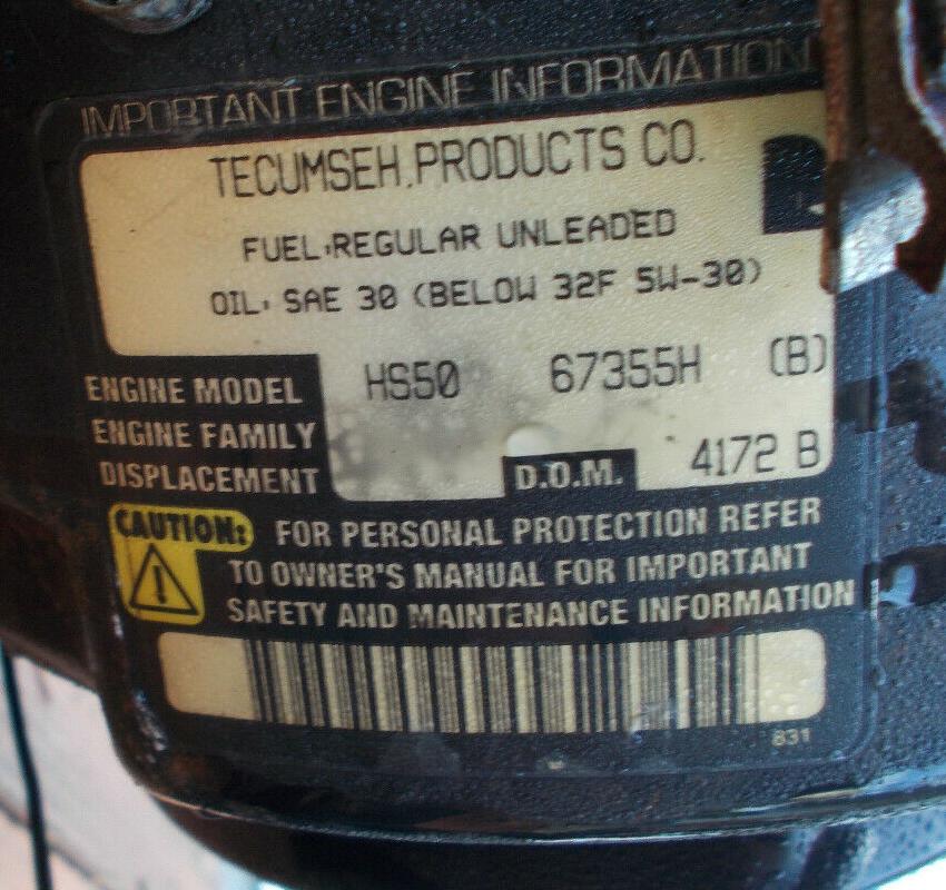
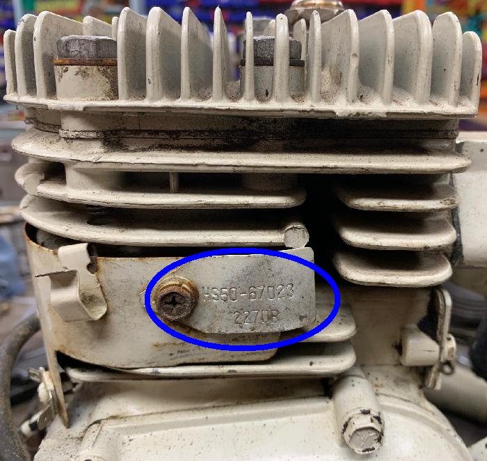
Serial number mounted on a tag. This happened on some motor pre-1975. First number is the
basic model (HS50). The '67023' number tells us the specifications of the motor. And the number '2270b' tells
us the motor was made on the 270th day of 1972.
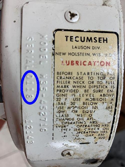
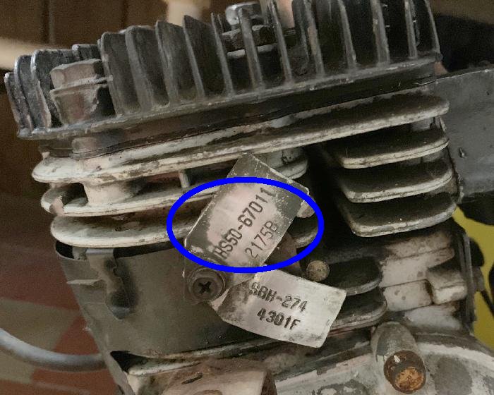
Serial number mounted on a tag. This happened on some motor pre-1975. First number
is the basic model (HS50). The '67011' number tells us the specifications of the motor. The number '2175b' tells
us the motor was made on the 175th day of 1972. The second tag shows that this motor was sold as a short
block. The motor may have been damaged, and a new short block was used to replace the original block.
-
Craftsmen Tecumseh motors used their own system of numbers. You can cross
reference the Craftsmen 143 number to a standard Tecumseh model/spec number using this
cross reference chart
to figure out which exact Tecumseh motor you have.

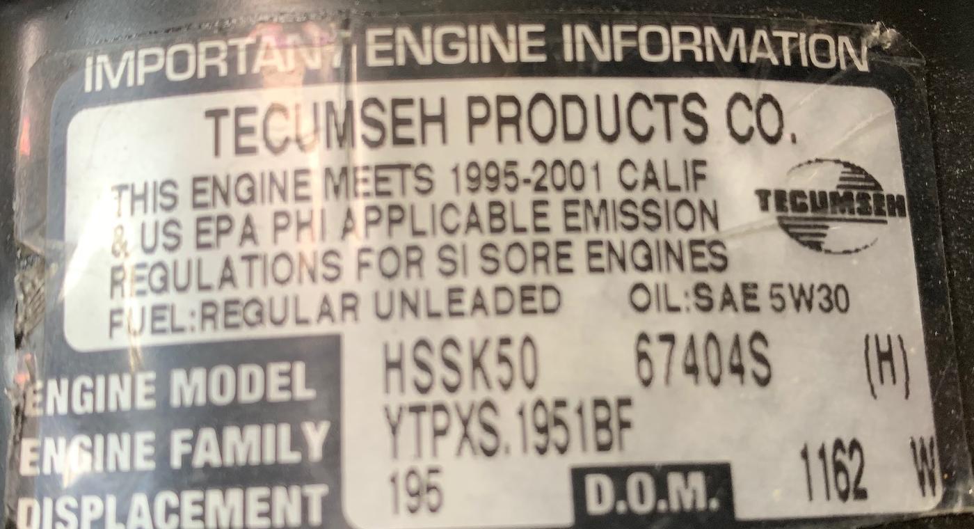
The new style Tecumseh date tag. This HSSK50 motor is a model S and was made on the 162nd day of 2001.
- HS50 (pre 1994) = 2.812" x 1.938" (or 2 13/16" x 1 15/16") 198cc, thick ring piston. These are HS50 models "G" and earlier and HSSK50 models "L" and "M".
- HS50/HSSK50/LH195 (1994 and later)* = 2.795" x 1.938" (or 2 51/64" x 1 15/16") 195cc, thin ring piston. These are HS50 models "H" and later and HSSK50 models "N" and later (basically models where the block is not painted.)
- HS50 (pre 1995) = models A to H (perhaps I too), large exhaust valve.
- HS50/HSSK50/LH195 (1995 and later) = models J and later, and all HSSK50/LH195 engines, small exhaust valve.
- HS40 (1968-1997) = 2.625" x 1.938" (or 2 5/8" x 1 15/16") 172cc
- HS40 (pre 1995) thick rings. These are HS40 models 55566K and earlier.
- HS40 (1995 and later) thin rings. These are HS40 models 55487K and later.
- H40 (released in 1998) = 2.500" x 1.938" (or 2 1/2" x 1 27/32") 156cc
- H35 (pre 1987) = 2.500" x 1.844" (or 2 1/2" x 1 27/32") 148cc
- H35 (1987 and later) = 2.500" x 1.938" (or 2 1/2" x 1 15/16") 156cc
- H30 (pre 1987) = 2.3125" x 1.844" (or 2 5/16" x 1 27/32") 127cc
- H30 (1987 and later) = 2.500" x 1.844" (or 2 1/2" x 1 27/32") 148cc
- AH817mb two cycle = 2.437" x 1.75" (or 2 7/16" x 1 3/4") 8.17ci or about 133cc or about 5hp at 5700rpm (32:1 gas/oil) (and yes the "MB" in the model is for "mini bike").
- A = 1972 to 1975 models. These will have an alloy flywheel and a points and condenser magneto with the small 16 degree nut/taper flywheel. Flywheel nut uses 11/16" socket.
- B/C = 1975 to 1979 models. These will have a points and condenser magneto with the small 16 degree nut/taper for the (cast iron) flywheel. Flywheel nut uses 11/16" socket.
- D = 1980/1981 models. This was the change to the larger nut for the flywheel and larger 10 degree flywheel taper. But these models still have points/condensor magneto. Flywheel nut uses 3/4" socket.
- E = 1982 to 1988 models. These will have the larger flywheel nut (10 degree taper) and often CDI ignition (non-snowblower applications.) They will also still have the 4 leg pull start (though the flywheel blower housing on CDI ignition E and F models is flat around the pull start, not raised like on earlier A-D model HS50 engines.) Flywheel nut uses 3/4" socket.
- F = 1988 to 1992 models. These will have the larger flywheel nut (10 degree taper) and all applications use CDI ignition. Most F models have the 4 leg pull start. But the cyclone pull-lite starter started to appear during the F series. On 4 leg pull start models, the flywheel blower housing is flat around the pull start, not raised like on earlier A-D model HS50 engines. Flywheel nut uses 3/4" socket.
- G/H and later = 1988 to 1995 models. These will have the "cyclone" style pull-lite pull start.
- I and later = 1994 and later models (also N and later HSK50.) Will have the smaller cylinder bore size with the thin rings. About the same time as the blocks where unpainted.
- J and later = Smaller exhaust valve.
- A = 1968 models, rounded blower housing with no top impressions, side model tag.
- B = 1970 models, rounded blower housing with top impressions, side model tag.
- C = 1970-1972 models, rounded blower housing with top impressions, side model tag.
- D = 1973-1974 models, square blower housing, alloy flywheel (?), side model tag gone.
- E = 1975-1978 models, square blower housing, cast iron flywheel.
- F = 1979 models, square blower housing, cast iron flywheel.
- G = 1980 models with points/condenser and larger flywheel taper.
- H = 1981 models with points/condenser and larger flywheel taper.
- I = 1983 models with points/condenser and larger flywheel taper.
- J = 1985 models, CDI ignition, 4 leg pull start with smooth face blower housing.
- K = 1988 models, CDI ignition, cyclone pull start, thick rings. For example 55565K.
- L = 1989-1990 models, CDI ignition, cyclone pull start.
- M = 1991ish models, CDI ignition, cyclone pull start.
- N = 1992ish models, CDI ignition, cyclone pull start.
Model Letter Transitions General Info.
* The smaller HS50/HSSK50 bore also came about at approximately the same times as a smaller exhaust valve. The smaller exhaust valve reduces knocking (pre-detonation) by reducing heat in the combustion chamber. Since the exhaust valve glows cherry red, it can ignite the fuel in the combustion chamber before the spark plug does. In normal (cam and carburetor) configuration, a smaller exhaust valve is a good thing, hence Tecumseh made that change in the mid-1990s (before the reduction in bore). Note on the HS40 the exhaust valve size never changed.
HS50 Model Letters Transitions by Year.
The leter following the model number on the HS50 can tell you
quite a bit about the engine. Remember the HS50 model started in 1972.
For minibike applications I personally like the HS50 A/B/C models
as this uses points and has the 16 degree (11/16" flywheel nut socket, 16 degree flywheel taper).
With the D and later HS50, the flywheel taper changed to 10 degree and
the socket required to remove the flywheel nut is now 3/4".
The ideal HS50 is any model pre-J, as you will get the larger exhaust valve. And if you don't want the 2cc smaller bore, any engine pre-I will give you that (though frankly that 2cc's isn't really a big deal, and the thinner rings used in the smaller bore do have advantages.) Also if you don't want a 'cyclone' style pull start, any HS50 model pre-H will give you the old style 4 leg pull start (though you can convert a cyclone pull start engine to use an older style 4 leg pull start and blower housing.)
HS40 Model Letters and other changes.
The leter following the model number on the HS40 can tell you
quite a bit about the engine. Remember the HS40 model started in 1968.
(Still working on this list.)
4. Is Your Snowblower Engine a Good Minibike Engine?
-
With the flathead Tecumseh motor out of the snowblower and on a table, you can evaluate
what is needed to be done to make it "minibike ready."
-
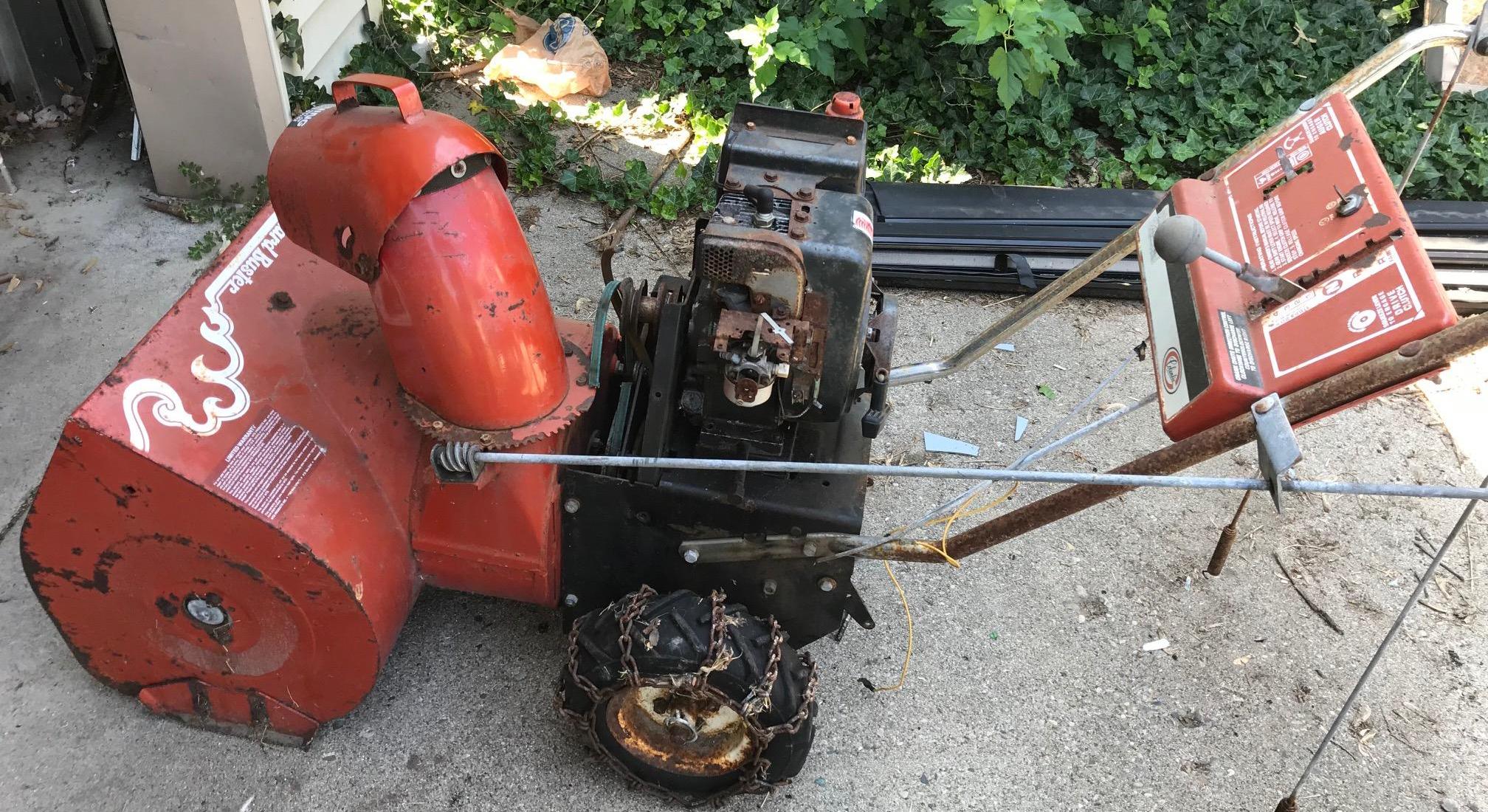
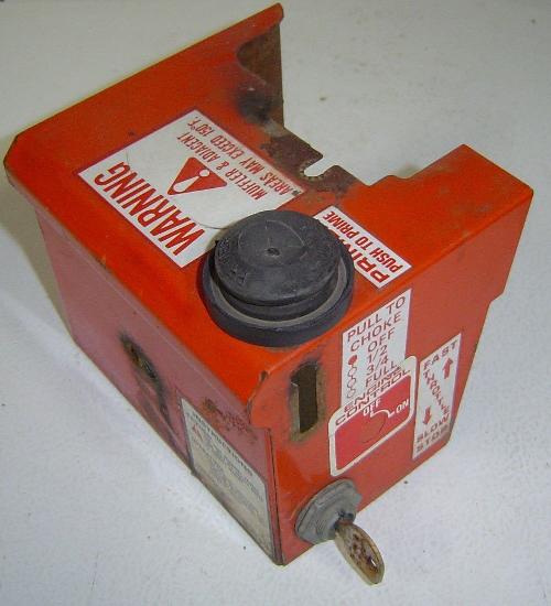
One thing you'll see on a lot of snowblowers is weird colors. Minibike
motor colors are generally white or black (or possibly silver, like
on MTD or 1970 model Rupps.) Orange (a common
snowblower motor color) was never used on a minibike. Not that this is
a big deal, but it's something to think about. If that bothers you,
get a different snowblower! Generally Toro and Ariens and Craftsmen will have
orange motors.
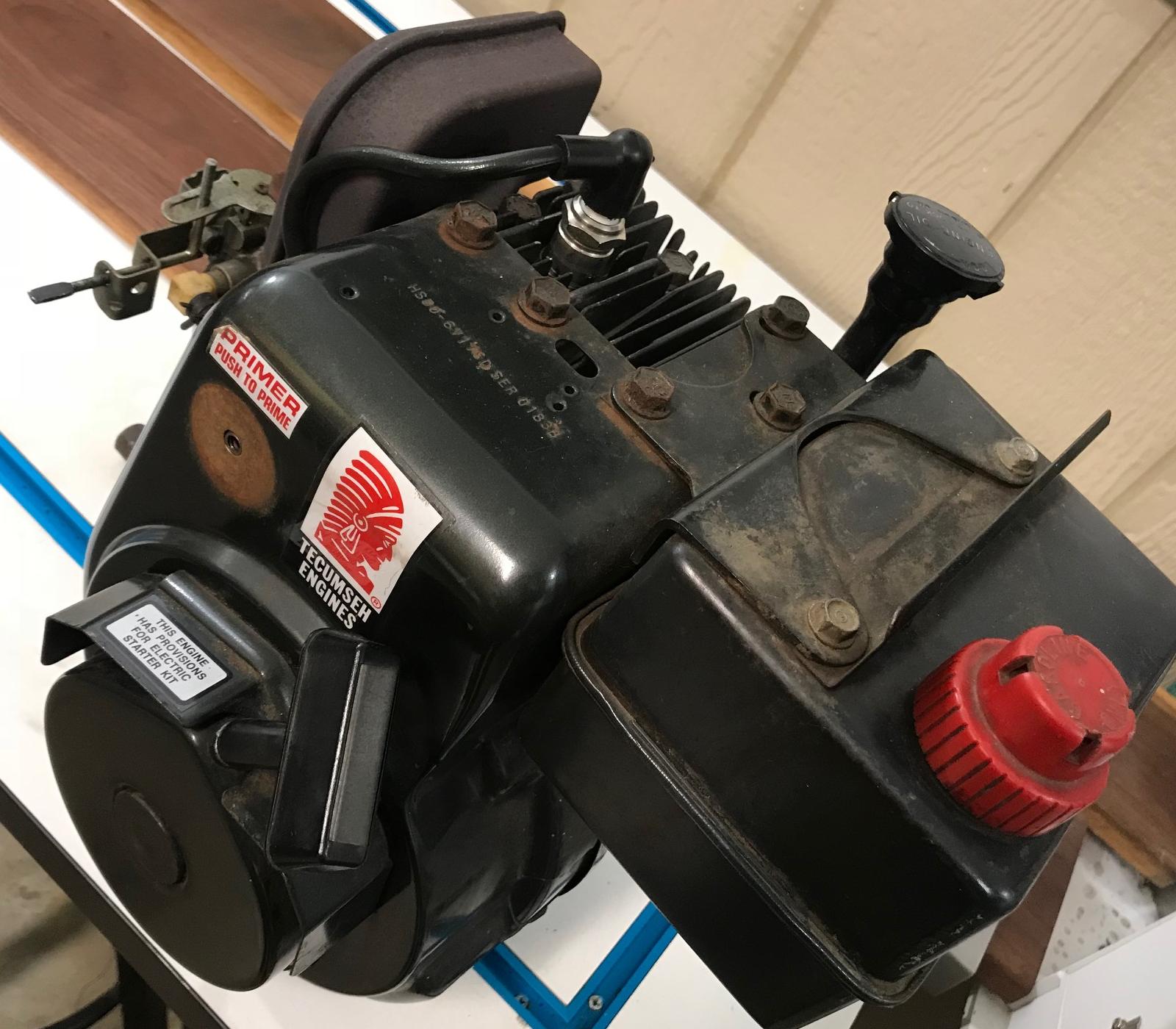
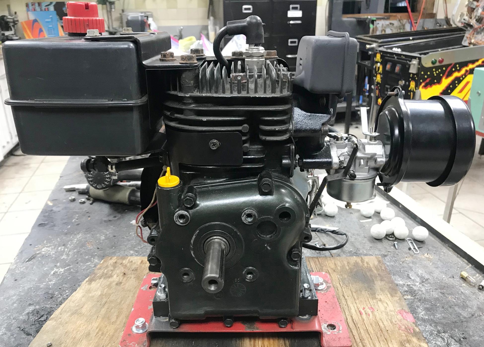
Here's a picture of the throttle assembly and the snowblower carburetor.
These both will be changed to minibike style, and an air cleaner assembly added.
This style muffler can be used on a minibike, though traditionally, it's not
really a minibike muffler.

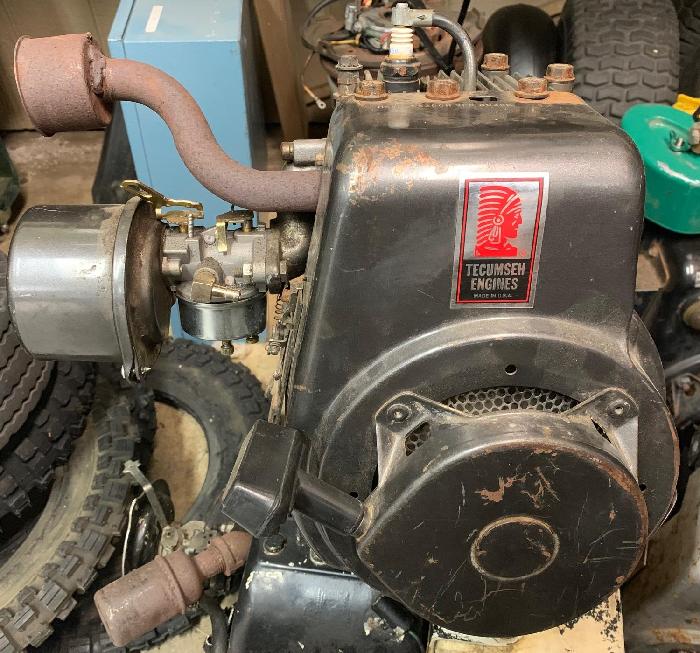
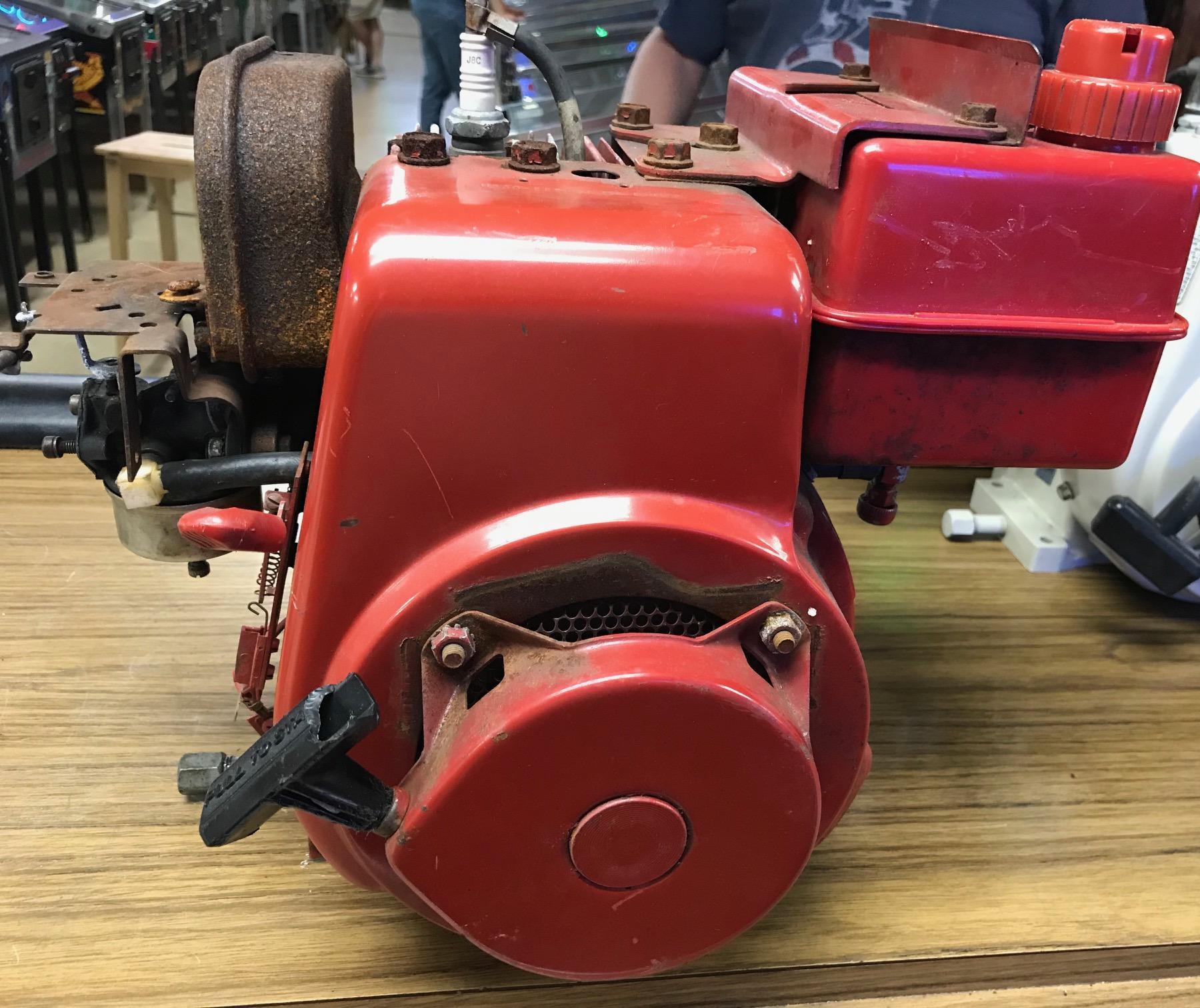
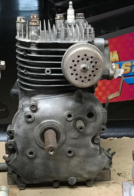
Here's a Tecumseh HS40 of a Toro snowblower. The orange color is not a deal breaker.
We can fix that color...
Testing a Snowblower motor before doing the conversion to minibike format, youtube video.
5. The PTO Output Shaft and Extended Cam Shaft and Side Cover.
-
One of the most important features about a donor motor is the PTO (power take off) output
shaft. That's the shaft which you ulitimately mount the clutch upon, and powers the
minibike. The PTO needs to be the correct size. The most common PTO size is 2.25" long
and 3/4" diameter. This is the "standard" mini bike shaft format. Longer
is OK (heck you can always cut the shaft, and if using a Torque Converter,
longer is an advantage.) But you never want shorter than 2.25" in length.
Note some Rupp HS40 motors have 2.75" in length. And some snowblowers also
use that length too. If you are running a torque converter, the longer
length PTO is a plus (though no required.)
-
Tecumseh 4 and 5hp motors generally will have either a 3/4" or 1" diameter PTO shaft.
Some Tecumseh 3 and 3.5hp motors can have a 5/8" diameter PTO. I would say to avoid motors
with a 5/8" PTO. Not because you can't use them, but it just limited the
number of clutch/torque converter options you have.
The 3/4" size is most desirable, but don't discount a 1" PTO shaft. It will
limit your clutch options a bit too, but it's still workable (and if you have
a metal lathe, you can turn a 1" shaft down to 3/4".) But for the most part,
having a 3/4" PTO with no taper is the ideal format for a minibike.
-
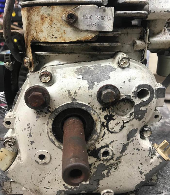
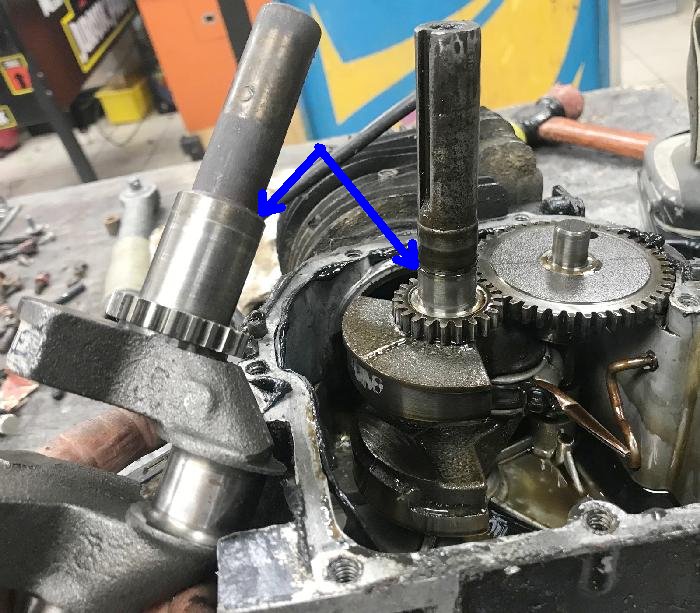
Note some Tecumseh snowblower motors will have a secondary camshaft extended PTO
(used on snowblowers and roto-tillers for reverse.) What Tecumseh did is lengthen the
cam shaft so it exits out the side case, and put another exterior gear/pully upon this
smaller shaft. Though not ideal, this is not a show stopper. The simple
reason is that the extended cam shaft can be cut (externally), and
the motor used as a single PTO shaft engine. The downside is this is
another seal and another place for the engine to potentially leak oil.
But for the most part, it's fine to just cut it clean externally.
-
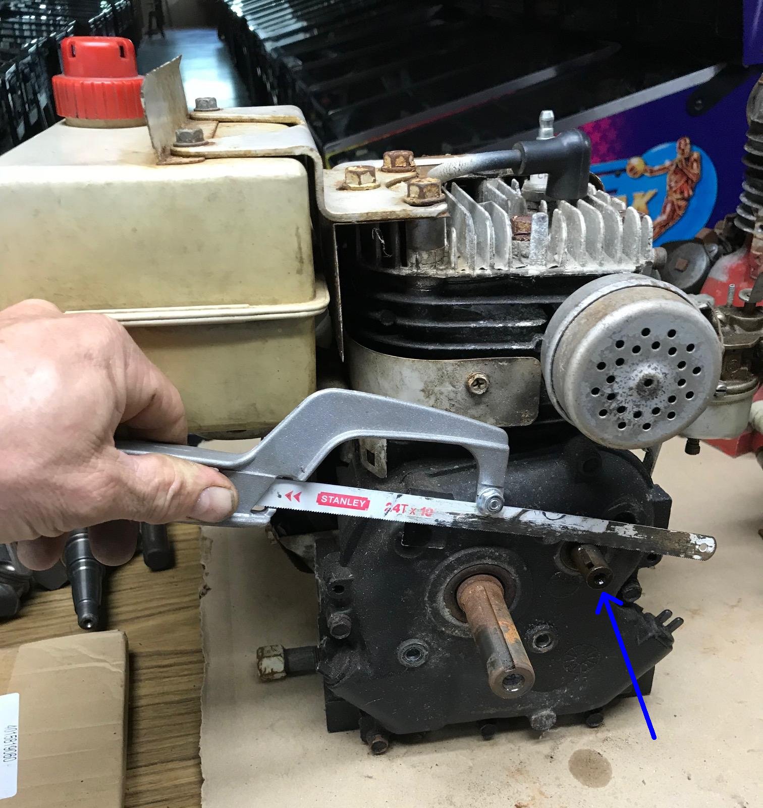
The easiest way to get rid of the secondary small cam shaft PTO is to start the motor,
and use a hacksaw blade to cut the shaft! This works amazingly well and is quick and
easy. A more time consuming way to remove the secondary PTO shaft is to "split the case."
That is, remove the side case, and remove the cam (easier than it sounds.) Then the cam
shaft can be cut to .6" from the large cam gear to the end of the cam (to get rid of the extended secondary PTO.)
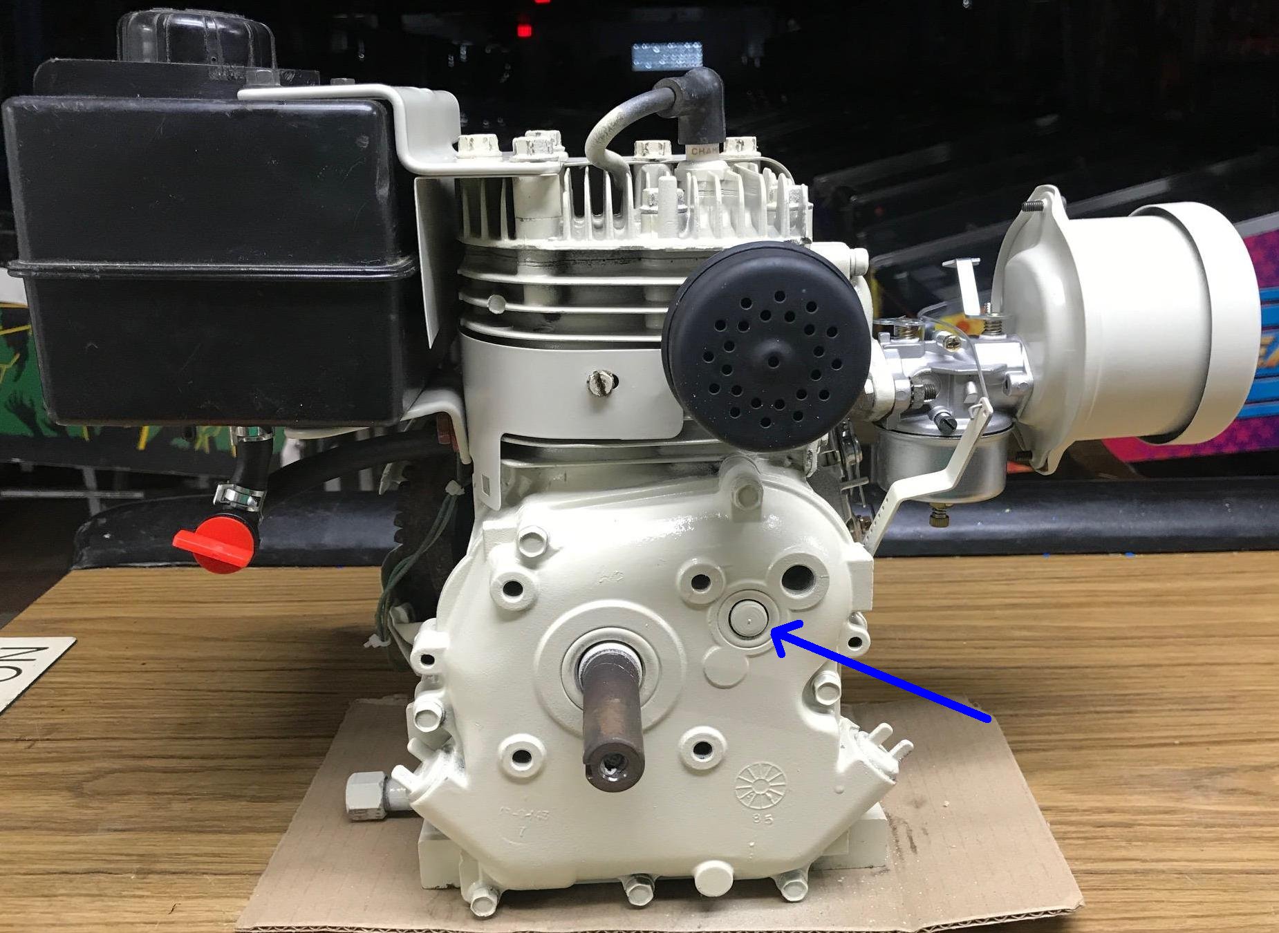
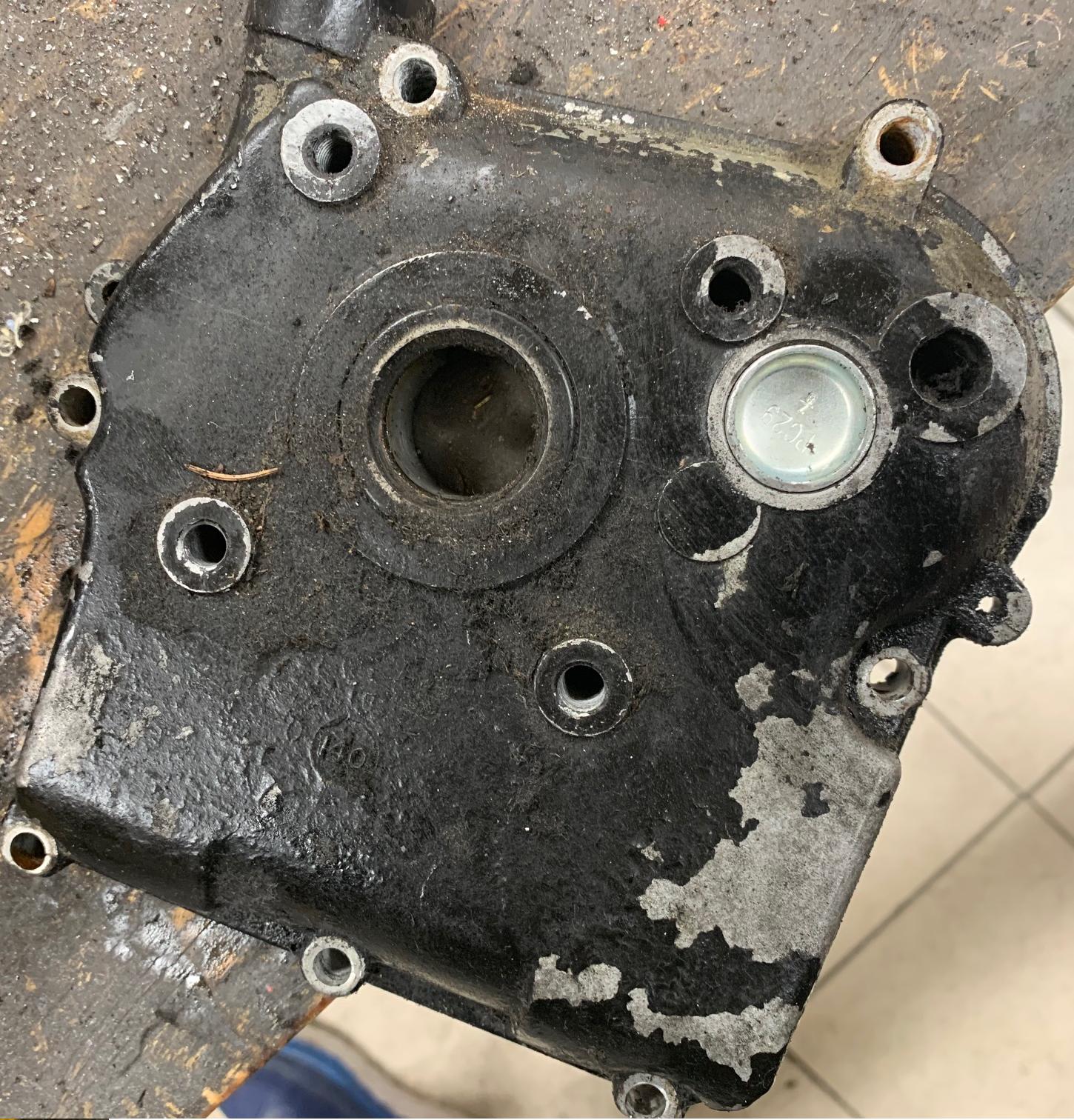
Unfortunately you will have to get a different side cover, one with only
the one main PTO hole. Or you can use a 7/8" freeze plug to fill the hole.
A different side sump cover is easy to get as most Tecumseh HS40 and HS50 motor from
pretty much any era will work (they are generally interchangeable.) Note that H30 and H35
side covers are generally different - the PTO bushing is only 7/8" diameter, where on
HS40/HS50 Tecumseh engines have a PTO bushing that is 1" diameter. Also in later HS40/HS50
side covers the casting of the sidecover lugs for the mount bolts got wider. Meaning
it may require one or two slight longer side cover bolts than say 1970s versions. Another variable is
the location of the oil fill (single or double low, or high). Generically the best minibike single
shaft side cover is Tecumseh #32700, but like I said, others will work too
(with the oil fill position being the main variable.) Don't discount high oil fill
PTO covers - though not a minibike thing, they sure are convenient to use!
-
Note if you remove the side case and keep the small PTO (say when you're removing the governor),
you may have problem with the seal around the small cam shaft PTO.
That seal does not like to have the cam removed,
meaning you can end up with a leak. I mention this because if you remove the internal
governor parts (which requires spliting the case), you may have problems with this seal.
-
If you remove the side case (for any reason), my suggestion is to cut the end of the cam shaft length to .580"
to .600", and get another side case without the small PTO cam shaft hole. Alternatively,
you can use a 7/8" .885 "freeze plug" PC29 (aka steel cup expansion plug) and some sealer,
and seal the side case cam shaft hole (after you cut the cam end to .580" to .600" in length.)
These plugs are available from
Dorman Products or
Advance Auto Parts.
Note the exact length of the end of the cam is approximate... this was originally cut on a bandsaw
at the factory, and the measurement varies. So keep the measurement at .580" to .600" and it
should work out fine.
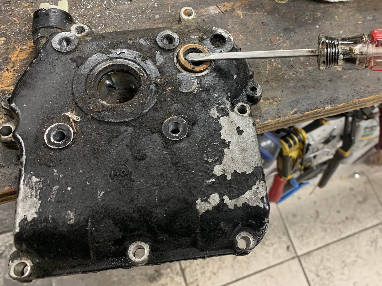
-
Before installing the new PC29 7/8" freeze plug, you need to remove the old seal. I use a screwdriver
and pry it out. Just through the seal away, you won't need it now. Also check the size of the hole.
I generally get .871" or close to that. Then check the size of the new PC29 freeze plug. It will
be larger than that, usually about .020" larger. You can't just hammer that into the hole!
Using a bench grinder, i take some meat off the sides of the PC29 plug, to get it down to about
.005" bigger than the sump cover's hole. Then you can hammer it into the side cover without
damaging anything.
-
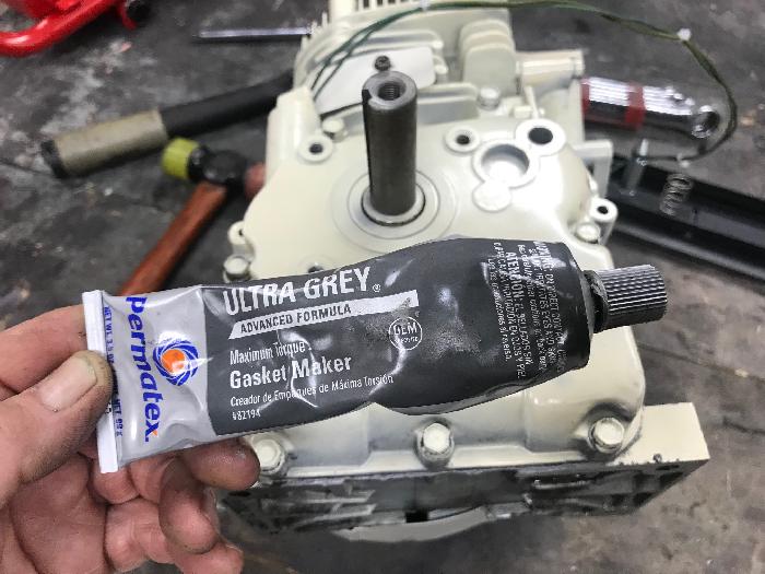
To install the freeze plug, I put the cover on a hard work bench or vice.
Then use a nylon hammer to get the freeze plug
into the side case cam hole. Afterwards I used a bit of Permatec Ultra Gray gasket
compound around the freeze plug, just to make sure it does not leak. Some people use
JB Weld for this... but either will work. Also not you can mount the freeze plug either way
(concave or convex.) I guess if you really want to be accurate, concave is the proper mount.
-
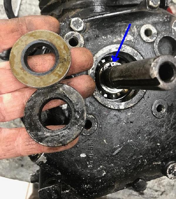
Note some HS40 and HS50 motors ("recreational motors") have a ball bearing side case
(opposed to bushing style.) These are easy to identify because
the side case seal is indented about a 1/4 of an inch, opposed to
a bushing side case seal which is flush with the side case.
The ball bearing side case #30756 is less prone to wear and
is generally considered to be a good thing for
a mini bike motor. Some makers, like Rupp, used ball bearing side cases
on their HS40 motors too, for better wear properties. The only downside to
a ball bearing side case is if you need to remove the side case... Removing a ball bearing
side case is more eloborate - the seal has to be pried out, and a "C"
clip exposed and removed to get the side case off. Hence you best have a spare
side case seal #28540, if you are going to remove a ball bearing side case.
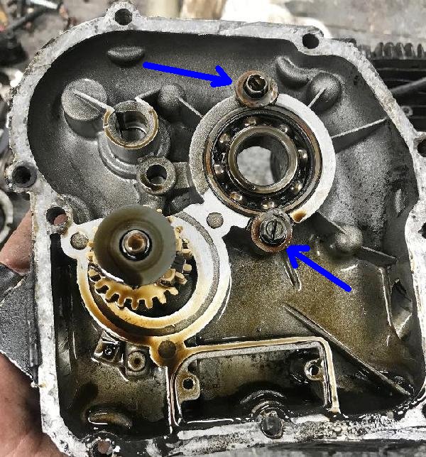
-
After the "C" clip is removed, the side cover will come right off. If you
look at the inside of the side cover, you can see why the "C" clip had to be
removed - the ball bearing is held in place with two screws/washers. If you
try and pry the side cover off without removing the exterior "C" clip, you
will destroy the ball bearing mount screws/washers.
-
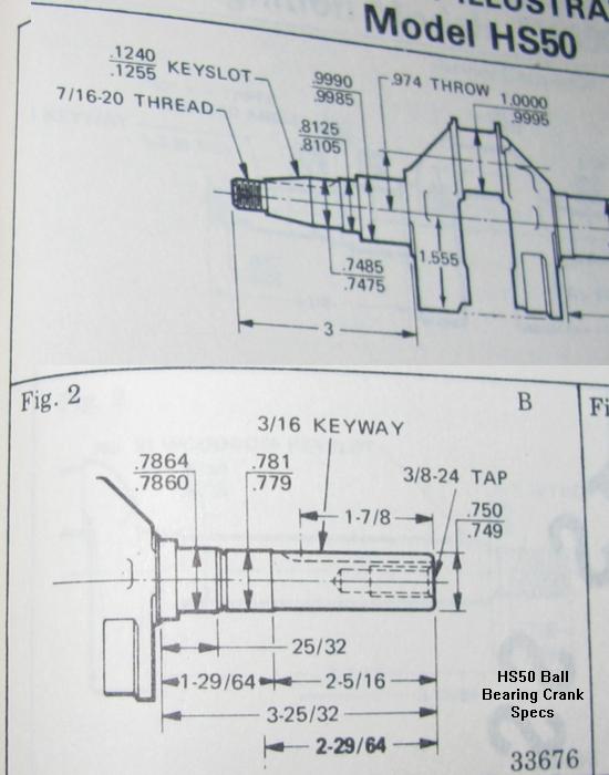
Note that the crankshaft used in motors with side case ball bearings
is different. The area that contacts the ball bearing is smaller than
a crankshaft used in a bushing side case motor. Bushing motors had
a .9985" surface contacting the bushing. On ball bearing side case motors the
crankshaft had .785" surface contacting the ball bearing. I guess in
theory you could turn a bushing crankshaft down and a C clip groove width of .0745",
making it a ball bearing crank.
Specs from Tecumseh on the Ball Bearing HS50 crankshaft.
6. Ignition - Points/Condenser or Electronic, and Flywheel material.
-
Prior to about July 1984, all Tecumseh motors used points
and condenser for the ignition. Tecumseh officially switched
to electronic (solid state CDI) ignition on August 1, 1984
(though on some models it took to 1985 to fully implement the change.)
This new system does not need
points/condenser. This change is a good thing
for the most part... Less parts to wear and maintain.
But the classic minibike motor used points/condenser.
Specifically, after August 1984 the HS50 "E" series (for non-snowblower engines) and
since April 1985 the HS50 "F" series (snowblower engines) used CDI solidstate ignition.
-
Also flywheel options are different between the two systems.
With the electronic ignition, all the flywheels will be
steel. With points and condenser, most flywheels are also steel,
but original minibike motors uses aluminum flywheels. The advantage to aluminum
is faster RPM gains when you hit the gas. The advantage to steel
is once you are to the desired RPM the momentum keeps you there
better. The year Tecumseh went to steel for all flywheels seems
to be 1975. Prior to 1975 and you'll find their engines (be it HS40 or HS50)
will be aluminum.
In the end, I'm not sure the flywheel material really matters all that much. All snowblowers will have a steel flywheel (often with "teeth" to accomodate electric start.) So frankly that choice is made for you. And you will, "get what you get", when it comes to electronic versus points/condenser. You can't change the system, so you'll have to deal with what you have. Also changing a steel flywheel to an alloy flywheel is harder than you may think. I mean you can do it, but it's tricky. So I don't sugguest that avenue, if you were thinking about that...
-
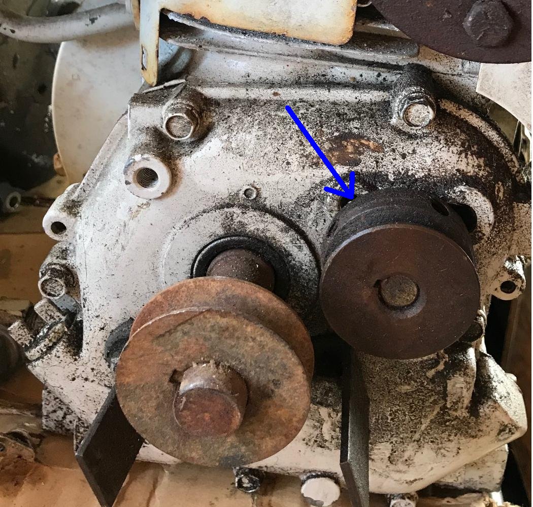
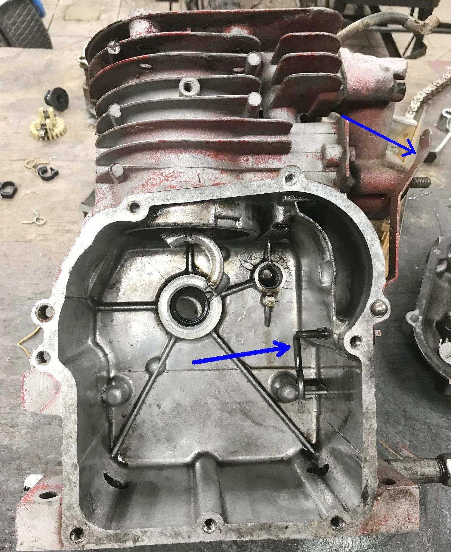
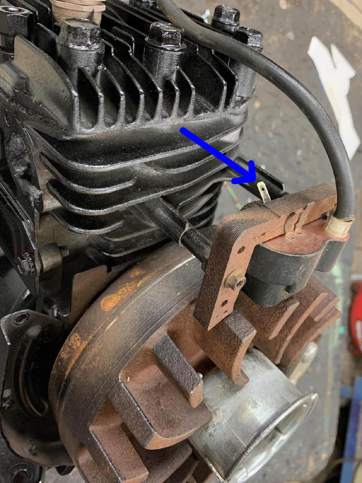
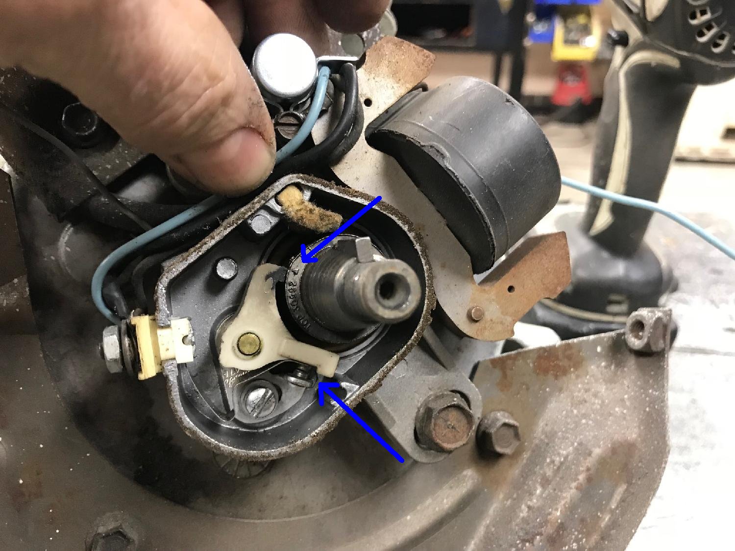
It's easy to tell the two systems apart. The coil (blue arrow in the
above picture) is external on electronic ignitions. On points/condeser
motors, the coil is internal (behind the flywheel). That means maintaining
the points/condenser requires removing the flywheel. We'll talk about
that later, but if you have a points/condenser motor, you will have
to remove that flywheel to maintain those parts.
Note flywheels are not necessarily interchangeable. The flywheel side of the crankshaft changed about 1981. The 'points condenser' crankshafts before 1981 had a .541" diameter end for the flywheel. The 1981 and later crankshafts had a .644" diamenter end for the flywheel. This change happened almost the same time as CDI (electronic) ignition came about (in 1985). But there were some points/condenser motros made with the larger crankshaft ends in the 1981-1984 era. These flywheels are not interchangeable between the two sizes. And they certainly are not interchangeable between points/condenser and CDI model engines.
7. Removing the Snow Parts.
-
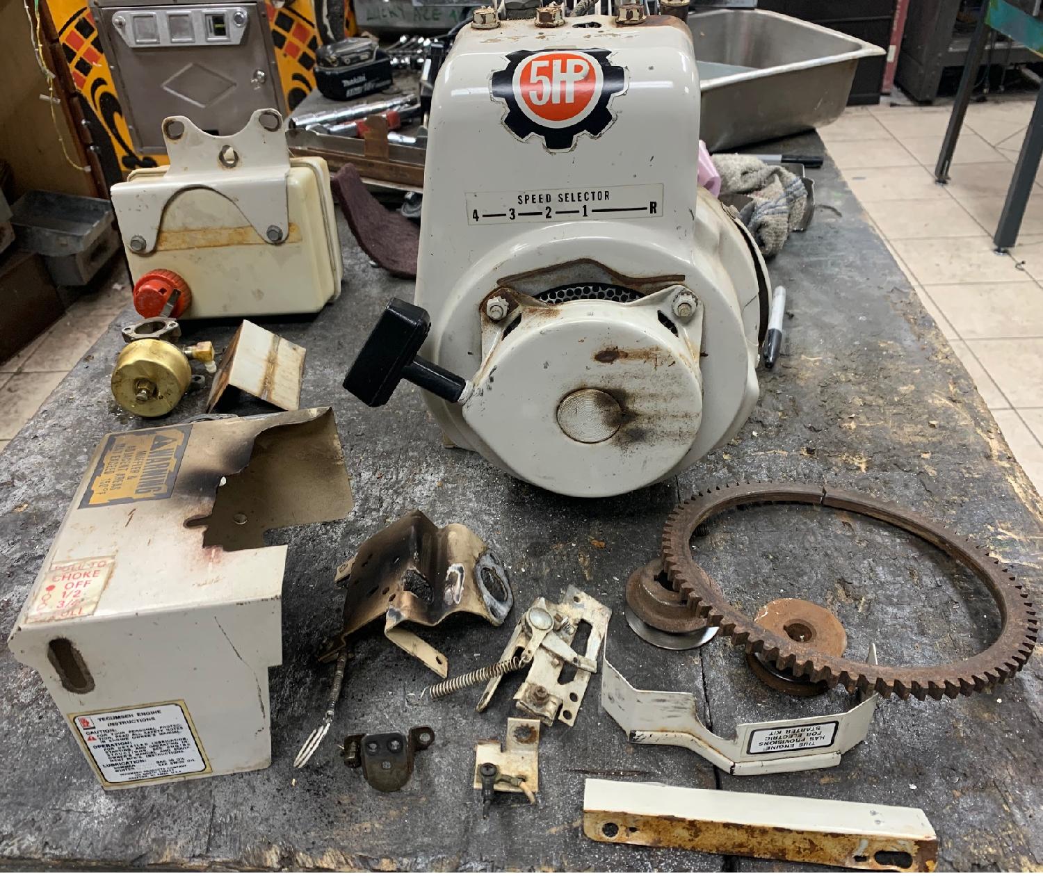
At this point it's a good idea to remove unnecessary parts from
the motor. Here's a list of what to remove:
- Remove the snow shields from around the carburetor, discard (keep screws).
- Remove the carburetor, discard (keep screws)
- Remove the blower housing (with pull start attached), keep.
- Remove the pull starter, keep. If it has a snow sheild around the top, discard.
- Remove PTO shaft pully, discard. Usually need a pully remover to do this.
- Remove the gas tank. If there is a snow shield, remove, discard.
- Remove the fuel line, discard.
- Remove the mufflier, keep.
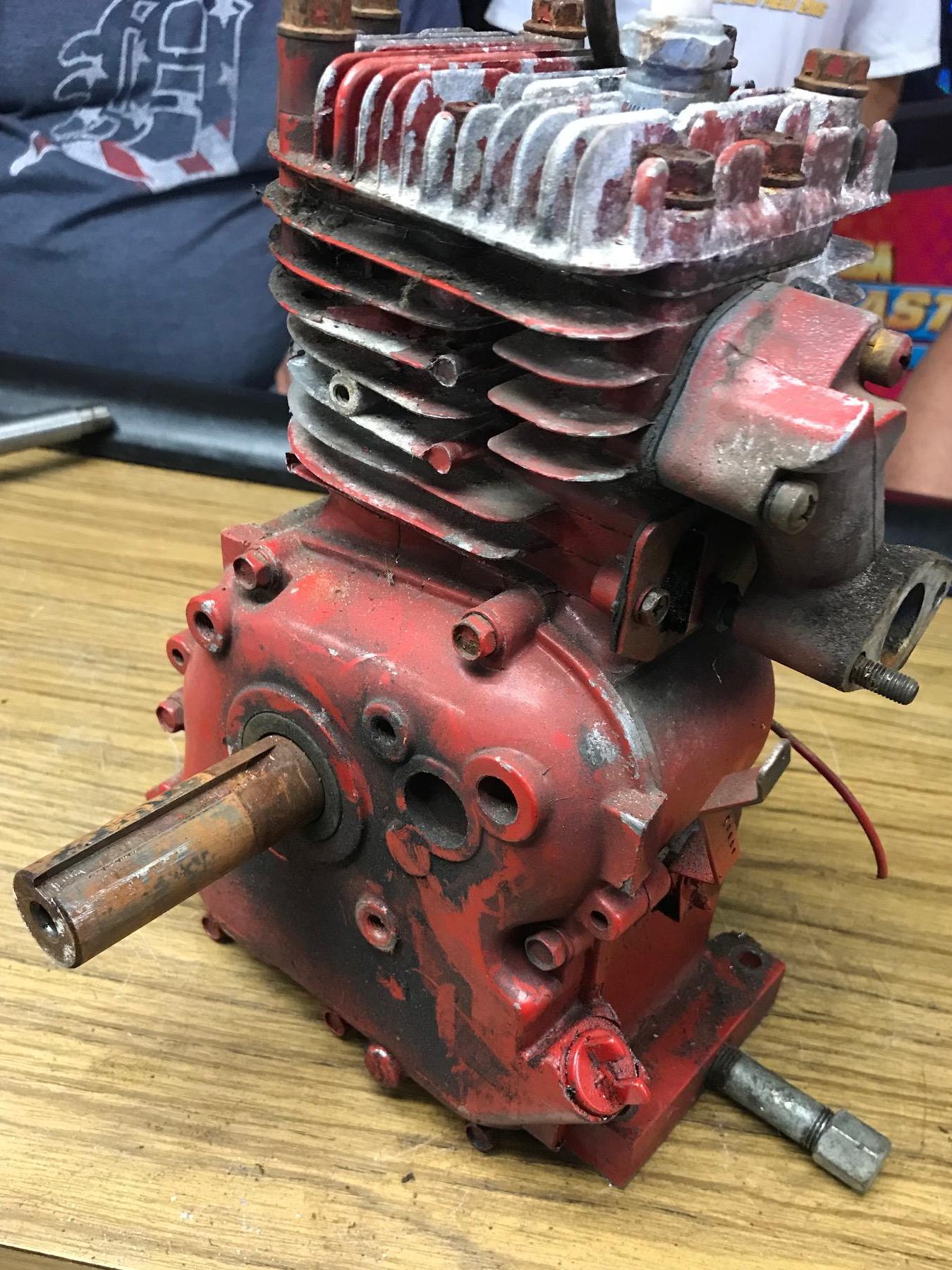
With these parts removed, you basically have a "long block" motor. Now we can deal with building the motor back up with minibike usable parts.
Parts are removed from the motor, making it a long block. Ready for some serious work!
-
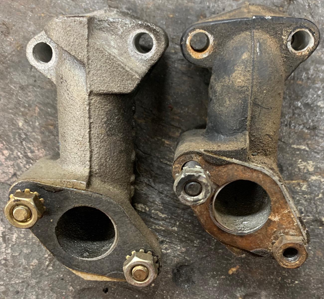
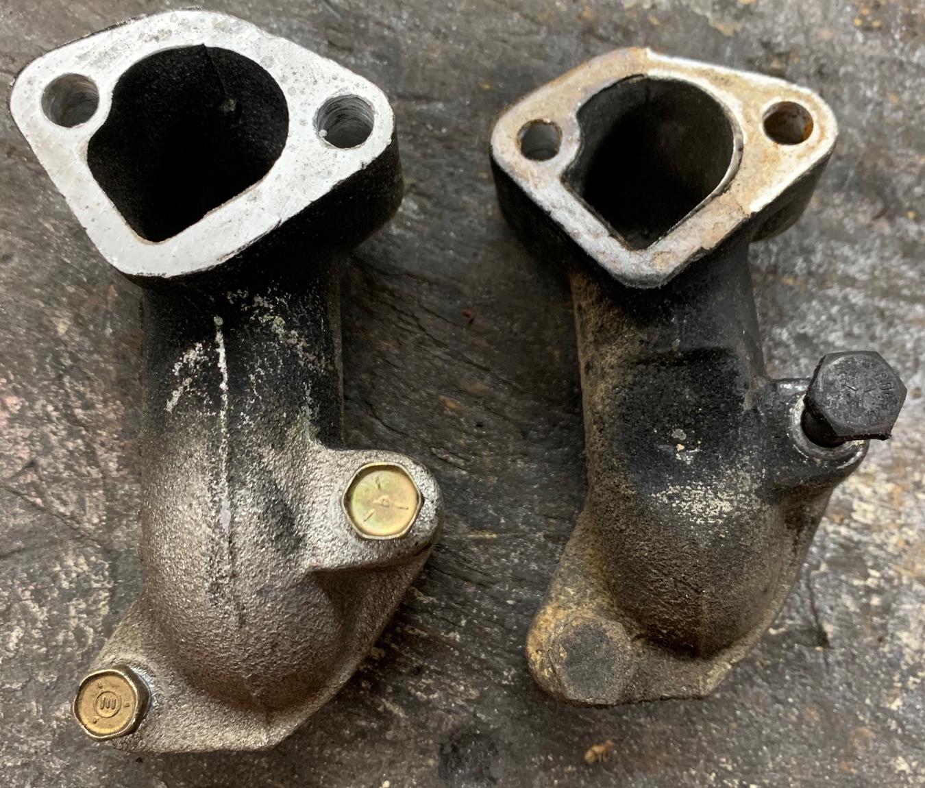
The HS50 intake manifold on a snowblower is slightly different than
a 'recreational' HS50 intake. It's certainly no deal breaker, but someone with
a keen eye could probably spot a snowblower intake versus a minibike
intake. The snowblower intake has more casting metal across the top
because of the snowblower air box that surrounds the intake and the carb.
Also the snowblower intake is just slightly longer. But again, unless
you really have a keen eye, this is not a noticeable feature.
Check out the picture below.
Left: HS50 snowblower intake.
Right:HS50 recreational (minibike) motor intake.
Notice the differences? (It's not a lot.)
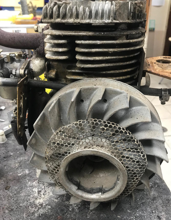
Below is a picture of an HS50 from a snowblower. In the
foreground are the snowblower parts that were removed and
discarded. In the left background are the gas tank and
carb, which may or may not be needed for your mini bike build.
8. Tecumseh Part Numbers.
-
Depending on your skill set and what your motor have or need,
there are some other parts that may be helpful to have.
Unfotunately things are necessarily easy, as Tecumseh
made some changes along the way.
- HS50 (approximately pre 1994) = 2.812" x 1.938" (or 2 13/16" x 1 15/16") 198cc, thick ring piston. These are HS50 models "G" and earlier and HSSK50 models "L" and "M".
- HS50/HSSK50/LH195 (approximately 1994 and later)* = 2.795" x 1.938" (or 2 51/64" x 1 15/16") 195cc, thin ring piston. These are HS50 models "H" and later and HSSK50 models "N" and later.
- HS40 (1968-1997) = 2.625" x 1.938" (or 2 5/8" x 1 15/16") 172cc
- HS40 (approximately pre 1994) thick rings. These are HS40 models 55566K and earlier.
- HS40 (approximately 1994 and later) thin rings. These are HS40 models 55487K and later.
- H50 = 2.625" (the fat body H50 also used the HS40 diameter bore, but had a longer bore.)
- H35 = 2.500" (pre-1990s)
- H25/H30 = 2.3125" (pre-1990s, with H25 discontinued around 1975)
- HS50 (pre 1995) = models A to H, large exhaust valve.
- HS50/HSSK50/LH195 (1995 and later) = models J and later, and all HSSK50/LH195 engines, small exhaust valve.
First a word about point/condenser versus CDI motors... When it states "points" this generally mean 1984 and before. And likewise "no points" (CDI) is late 1984 and later. This is a general rule to keep in mind.
On crankshafts and flywheels a change in 1982 brought about a larger flywheel nut and less taper on the flywheel side of the crank. This kind of corresponded with the change from points/condenser to electronic ignition, not perfectly, but roughly (technically though the change from points to electronic ignition was August 1st 1984.) In 1981/1982 there were some motor with both the new style less taper crankshaft (3/4" flywheel socket needed, instead of 5/8" socket) and points - This happened only for a short time. Note the early pre-1981 crankshafts with more taper used a 7/16-20 nut (5/8" socket), and the later crankshafts with less taper used a larger 1/2-20 nut (3/4" socket). On HS50 engines, the A/B/C series (letter after the five numbers following "HS50") used the smaller taper flywheel. Starting around series D or E on the HS50, the flywheel taper changed. And E series HS50 engines generally had CDI ignition.
Also on HS50 motors they changed the cylinder bore at some point (2.795" newer HS50, 2.812" older bore), I believe in the 1990s. This change happened when they decreased the exhaust value size slightly to accomodate EPA emission regulations (HS50 models "H" and later and HSSK50 models "N" and later.)
Another note... HS40 and HS50 do *not* use the same crankshaft. The counterweights are different (though pretty much every other dimension is the same.)
Note the change during the 1990 from the old style thick rings to thinner rings. The thinner rings used less oil and hence less emmisions. Sometimes these are known as the "UK version", I guess because the change was implemented overseas first. The thin ring piston is different too, with less side shirt and obviously thinner gaps for the rings. But the newer thin ring style piston/rings for HS40 works fine in the old vintage 1970s and 1980s HS40 motors. And in some ways is more desirable because there is less cylinder wall contact with the piston and rings.
On the HS50 motors, the newer thin ring piston are slightly different in size (as they are really HSSK50/HSSK55/LH195 piston/rings), and will *not* work in 1972-1990 HS50 motors. Why? Because the piston size is different. With the newer thin ring piston, they changed the piston size from 2.812" (old thick ring piston) to 2.795" (thin ring piston.) So these, unlike the HS40, are not interchangable.
Tecumseh motor bores and ring styles:
Tecumseh HS50 exhaust valve styles:
-
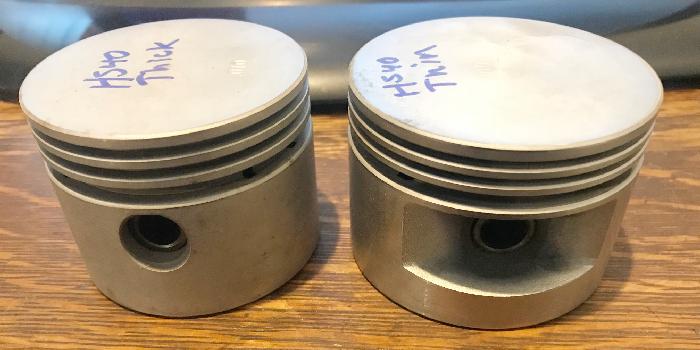
It's important to note the difference in the thick and thin rings
as used on HS40 and HS50 engines.
Because on the internet, these part numbers get cross referenced.
You need to know what is what, so you get the correct rings/piston.
Especially if you buy pistons or rings on ebay. The part numbers
just get crossed, and you may not order what you really want. I highly
suggest you look closely at the pictures, as it's easy to identify
a thin or thick ring piston and thin or thick rings. Thin and Thick
rings are a huge deal on HS40 and HS50 engines. The thin rings (and piston
that holds them) came about in the 1990s:
- HS40 minibike short block (1970-1972): #754186
- HS40 mini bike replacement engine (1970-1972): #904415
- HS40 minibike short block (1972 speedway): #754153b
- HS40 short block, universal, points or CDI, 1969 to 1997: #36561
- HS50 minibike block (1972 speedway, no parts): #33674
- HS50 minibike short block (1972-1974): #754192
- HS50 mini bike replacement engine (1972-1974): #905420
- HS50/HSSK50 crankshaft 3/4" PTO new style (CDI): #34740
- HS50/HSSK50/LH195 crankshaft 7/8" PTO new style (CDI): #37842 (pto too big)
- HS50 crankshaft 3/4" PTO old style (points) bushing style: #33677
- HS50 crankshaft 1" PTO old style (points) bushing style: #33675 (pto too big)
- HS50 crankshaft 3/4" PTO old style (points) ball bearing case points (1980 to 1984): #34728
- HS50 crankshaft 3/4" PTO old style (points) ball bearing case points (1972 to 1980): #33676
- HS40 crankshaft 3/4" PTO new style CDI (no points): #34734
- HS40 crankshaft 3/4" PTO old style (points): #32877
- HS40 crankshaft 3/4" PTO old style (points), 3" pto (Fox): #33012
- HS40 crankshaft 3/4" PTO old style (points): #33197 (PTO keyway short, will need work to use on minibike)
- HS40 crankshaft 3/4" PTO old style (points), ball bearing (not bushing), 3" pto, Rupp style: #33080
- HS40/HS50 connecting rod: #32875 or 32875a
- OHH connecting rod: #32875b (more meaty)
- HS40/HS50/HSSK50 valve lifter (intake/exhaust the same length): #27241
- LH195sp valve lifter (intake/exhaust same, both longer than hs50 lifters): #37670
- HS40/HS50 valve spring (intake/exhaust the same length): #31672
- HS40/HS50 valve spring cap lower retainer (intake/exhaust the same): #31673
- HS40 valve spring cap upper retainer (small hole version): #27883
- HS50 valve spring cap upper retainer (big hole version): #27882
- HS40/HS50/HSSK50 intake valve and lower retainer: #32644
- HS40/HS50/HSSK50 intake valve and lower retainer: #32645 (oversize 1/32" for worn valve guide)
- HS40/HS50 exhaust valve and lower retainer (large valve): #29313
- HS40/HS50 exhaust valve and lower retainer (large valve, oversize 1/32"): #29315
- HS50/HSSK50 exhaust valve and lower retainer (small valve): #36471
- HS50/HSSK50 exhaust valve and lower retainer (small valve, oversize 1/32"): #36472
- Motorsport aluminum valve spring lower retainer and clips: 37259k
- HS40/HS50/HSSK50 cam bump compression release (BCR): #33158
- HS40/HS50/HSSK50 cam BCR extended length (snowblower reverse): #34688
- HS40 cam mechanical compression release (MCR): #32701
- H30/H35 cam (no compression release): #31317
- H30/H35 cam (bump compression release): #33149
- H30/H35 cam (mechanical compression release): #32197
- LH195sp cam mechanical compression release (MCR): #37040.
Note this cam is available in metal or plastic! If you're looking on ebay and it comes with
valve springs, don't buy it! The lighter duty valve springs are for the plastic cam (also there
are "splines" behind the exhaust lobe of the plastic cam.) The metal
version of 37040 uses standard HS50 valve springs. This #37040 part number replaces the original #33158
cam (BCR) HS50 cam on many websites. I don't recommand this cam.
- HS40 head gasket: #33015
- HS50 head gasket: #33554 asbestos old style, discontinued.
- HS50 head gasket: #36443 mew style graphite based, asbestos free.
- HS40/HS50 head: #33016 or #37675
- HS40 gasket set: #33240
- HS50 gasket set: #33683 (or #36444 with two less gaskets)
- HS40/HS50 side cover gasket: #27677
- Note that 1970 and later HS40 and all HS50 heads are identical
(aside from perhaps spark plug wire routing.)
But the head gaskets are not the same (due to difference sizes in combustion chambers).
--- - HS50 piston/pin/rings assembly (thick rings): #34535
- HS50 piston/pin/rings assembly (thick rings): #34536 (.010 over)
- HS50 piston/pin/rings assembly (thick rings): #34537 (.020 over)
- HS50 piston/pin (thick rings): #33562
- HS50 piston/pin (thick rings): #33563 (.010 over)
- HS50 piston/pin (thick rings): #33564 (.020 over)
- HS50 piston rings (thick): #33567
- HS50 piston rings (thick): #33568 (.010 over)
- HS50 piston rings (thick): #33569 (.020 over)
--- - HS50 piston/pin/rings assembly (thin rings): #40004 (replaces #36073)
- HS50 piston/pin/rings assembly (thin rings): #40005 (.010 over, replaces #36074)
- HS50 piston/pin/rings assembly (thin rings): #40045 (.010 over, replaces #40005)
- HS50 piston/pin/rings assembly (thin rings): #36075 (.020 over)
- HS50 piston/pin (thin rings): #36070
- HS50 piston/pin (thin rings): #36071 (.010 over)
- HS50 piston/pin (thin rings): #36072 (.020 over)
- HS50 piston rings (thin): #40006 (replaces #36076)
- HS50 piston rings (thin): #40007 (.010 over, replaces #36077)
- HS50 piston rings (thin): #36078 (.020 over)
--- - HS40 piston/pin/rings assembly (thick rings): #34520
- HS40 piston/pin/rings assembly (thick rings): #34521 (.010 over)
- HS40 piston/pin/rings assembly (thick rings): #34522 (.020 over)
- HS40 piston/pin (thick rings): #32603
- HS40 piston/pin (thick rings): #32604 (.010 over)
- HS40 piston/pin (thick rings): #32605 (.020 over)
- HS40 piston rings (thick): #34854 (or #33315)
- HS40 piston rings (thick): #34855 (.010 over)
- HS40 piston rings (thick): #34856 (.020 over)
--- - HS40 piston/pin/rings assembly (thin rings): #35544
- HS40 piston/pin/rings assembly (thin rings): #35545 (.010 over)
- HS40 piston/pin/rings assembly (thin rings): #35546 (.020 over)
- HS40 piston/pin (thin rings): #35541
- HS40 piston/pin (thin rings): #35542 (.010 over)
- HS40 piston/pin (thin rings): #35543 (.020 over)
- HS40 piston rings (thin rings): #35547
- HS40 piston rings (thin rings): #35548 (.010 over)
- HS40 piston rings (thin rings): #35549 (.020 over)
- HS40/HS50 side case oil seal PTO side (bushing style): #27897 (typical of a snowblower motor)
- HS40/HS50 side case oil seal PTO side (ball bearing style ala Rupp): #28540
- HS40/HS50 side case ball bearing (as used on Rupp Tecumseh motors): #28458
- HS40/HS50 side case ball bearing clip: #28539
- HS40/HS50 side case oil seal magneto side: #32600
- HS40/HS50 side case gasket: #27677
- H50 side case oil seal magneto side: #27876
- H50 side case oil seal PTO side: #28427
- Side case alignment dowel: #26727
- HS40/HS50 side case cover, single PTO hole, bushing, low oil fill: #32700
- HS40/HS50 side case cover, single PTO hole, bushing, high oil fill: #34674
- HS40/HS50/H35/H30/H25 side case cover, single PTO hole, ball bearing, low oil fill: #30756b/30756c
- Oil fill plug no dip stick: #27625
- Oil fill plug with dipstick, level motor mount: #34245
- Oil fill plug with dipstick, 20 degree motor mount: #32969
- Oil fill plug with dipstick, for high fill location: #31297 (ideal) or #37884 (will work)
- Oil fill plug gasket: #36832
- Plastic fan for cast iron flywheel: #610933
- HS40/HS50 lighted steel cast iron flywheel (CDI): #611203 (or #611093 for 8/9/10hp engines)
- HS40/HS50 steel cast iron flywheel (CDI): #611081
- HS50 alloy flywheel (points 1972-1974 A,B,C engines): #33659
- HS50 lighted alloy flywheel (points 12 magnets A,B,C engines): #35660
- HS40/HS50 steel cast iron flywheel (points 1975 to 1980 with ring gear): #33701
- HS40/HS50 steel cast iron flywheel (points 1975 to 1980 with NO ring gear): #33695b
- HS40/HS50 steel cast iron flywheel (points 1980 to 1984): #611029 or #611024 (ring gear/no ring gear)
- HS40/HS50 lighted steel cast iron flywheel (points 1975 to 1980): 33660c
- HS40/HS50 lighted alloy flywheel (points 1975 to 1980) with glued magnets: 33660a
- HS50 lighted alloy flywheel (points) with embedded magnets: #610864
- HS40/HS50 (lighted or not) magneto timing cam breaker ring (activates the points): #30992
- H30/H35 (lighted or not) magneto timing cam breaker ring (activates the points): #30552
- HS40/HS50/H30/H35 (lighted or not) nylon flywheel spacer used on CDI engines (HS50 "H" and later): #34080
- HS40 alloy flywheel (points): #32517 or #610754
- HS40 lighted alloy flywheel (points): #610769
- HS40 alloy flywheel (points, electric start gear): #610845
- H50 lighted alloy flywheel (points): #30755
- LAV35 alloy flywheel (points): #31331
- H35 alloy flywheel (points) steel core: #31332
- H30 alloy flywheel (points) steel core: #1267 (aka #30542 and #29165 and #30367)
- H30 alloy flywheel (points): #610781
- H25/H30/H35 lighted alloy flywheel (points 1963-1974): #32338A
- LAV35 allow flywheel (points) alum core: #32159 (replaces #610782)
- H30/H35 allow flywheel (points, electric start gear) alum core: #610757
- CDI "hot" coil: #36605K (used for modified motorsport Tecumseh engines)
- CDI alternator lighting coil 350ma (exterior mount): #34960
- CDI alternator lighting coil 18watt (interior mount requires flywheel #611203): #611111
- CDI alternator lighting coil 3amp (interior mount requires flywheel #611203): #611095 or #611104
- Alloy flywheel pull start cup (for say #32517 flywheel): #590416
- Flywheel screen around starter cup (for #590416 starter cup): #33668 or #590417
- Pull start assembly (old style 4 leg): #590420
- Pull start handle: #590387
- Flywheel key, HS40 and HS50 (except D/E series), step style: #610951
- Flywheel key, HS40 (later) and HS50 D/E series, step style: #610961 (deeper step cut)
- Flywheel key, NO step: #611298 (CDI flywheel key, though often used on points flywheels)
- Flywheel key, H50 (pre-1981): #30884
- Flywheel key, H50 (1981 and later): #32589
- Flywheel gas line keeper clip (pre-1975 with front mount gas tank): #20443
- Flywheel gas line keeper bracket (1975 and later with front mount gas tank): # 34212
- Breather assembly: #31337 (best version to get has a rubber breather tube)
- Breather assembly gasket: #31619
- HS40/HS50 blower housing (1973 era, square top): #33663
- Condenser: #30548b
- Points: #30547a
- Points cover aluminum: #30550 (or #610947)
- Points cover gasket (small hole with foam): #610948
- Points cover gasket (small hole no foam): #610955
- Points cover gasket (large hole with foam): #610957
- Points cover gasket (large hole no foam): #32052
- Points cover wire: #30511
- Points magneto stator assembly (non lighted): #30561B
- Stator plate (no windings) non-lighted HS40 for 32517 alloy flywheel: #30545
- Points coil only: #30560
- CDI magneto stator: #34443
- CDI magneto under-the-flywheel: #610893
- Spark plug cover (aka boot): #610118
- Spark plug shorting clip: #30747
- HS40 magneto non-lighted (uses #32517 flywheel): #610755
- HS40 magneto lighted 12v 3a two circuits (uses #610759 flywheel): #610827, #610778, #610838
- Air cleaner assembly: #730127 or #730164 (both mount plates)
- Air cleaner mount plate: #31691 or #31914 (offset)
- Air cleaner body: #31715
- Air filter paper: #30727
- Air filter foam: #31700
- Air cleaner gasket: #27272A
- Intake manifold HS40 slant style: #33301
- Exhaust L shape: #35771
- Exhaust L shape with pipe: #37684
- HS40,H35,H30 Exhaust gasket: #33170
- HS50 Exhaust gasket: #33670
- HS40 Intake gasket: #32649
- HS50 Intake gasket: #33673
- Gasket set HS40: #33240
- Gasket set HS50/HSSK50: #33683 or #36444
- Carb HS40/HS50 aka Tecumseh service carb (transfer your choke): #631795
- Carb choke lever (mini bike): #631625
- Carb diaphragm H30/H35 slant mount: #631595 (stamp number on body #379)
- Carb diaphragm HS40 slant mount: #631588 (stamp number on body #356)
- Diaphragm & Gasket carb rebuild kit 236B #630978
- Diaphragm & Gasket carb rebuild kit complete #631893
- Diaphragm Inlet Needle, Seat, Gasket, Spring carb rebuild kit 236A #630932a
- Carb float: #632019 (metal) or #632802 (plastic)
- Carb float repair kit: #31840
- Lazy Susan engine display: #696348
Thick Rings: two top compression rings are .092" thick. Bottom oil ring is .153" thick.
Thin Rings: two top compression rings are .060" thick. Bottom oil ring is .121" thick.
Also note on thick ring HS40 engines, if you can't find rings, there is a trick. You can use H50 and H60 rings (just the top two compression rings, the oil ring is different.) This is because some H50/H60 models have the same 2.625" bore as an HS40. Not ideal (as you can't use the H50/H60 oil ring), but in a pinch I hear it works. These are part numbers 33315/33316/33317 (std/010/020.)
The HS40 seems to be the most abused motor. You see a lot of 1970s HS40 motors with worn cylinders. The bore was 2.6250 and the piston size is 2.6215 with a .0035 piston-to-wall clearance (Tecumseh specs are .004 to .006 on inspection.) If the cylinder is actually .008 big/tapered/scratched, a +.010 piston won't fix the problems, you just can't get the issues fixed with that little material to work with. So the Tecumseh #35546 piston (.020 over) is the best choice to resize the HS40 cylinder. Tecumseh says to use a rigid hone (like Sunnen AN-112) to resize and 390 grit stones. Well 400s are what's available and they must be silicon carbide. The only lubricant to use is Goodson Honing Oil or automatic trans fluid.
Head Gaskets on the HS40 and HS50 motors are different! You can't not mix them. Yes they are the same outside shape, but the HS50 head gasket is cut wider on the inside. This accomodates the larger bore on the HS50. If you put an HS40 head gasket on an HS50 engine, it will not run right!
9. Governor - Remove or Keep? (Connecting Rod and Side cover replacement)<
-
The governor's job is to keep the motor from sustained high RPMs.
These Tecumseh motors are designed for a maximum RPM of 3600.
And frankly, they don't like to stay at that RPM level for any
length of time (more than say 5 seconds.) As a kid I was always
asked on my minibike, "did you remove the governor so it would go faster??"
I was never sure what the governor was, much less how to remove it!
Good thing too. Because a de-governor motor and a 10 year old are almost for sure
going to throw the connecting rod, pretty much ruining the motor.
-
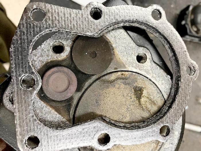
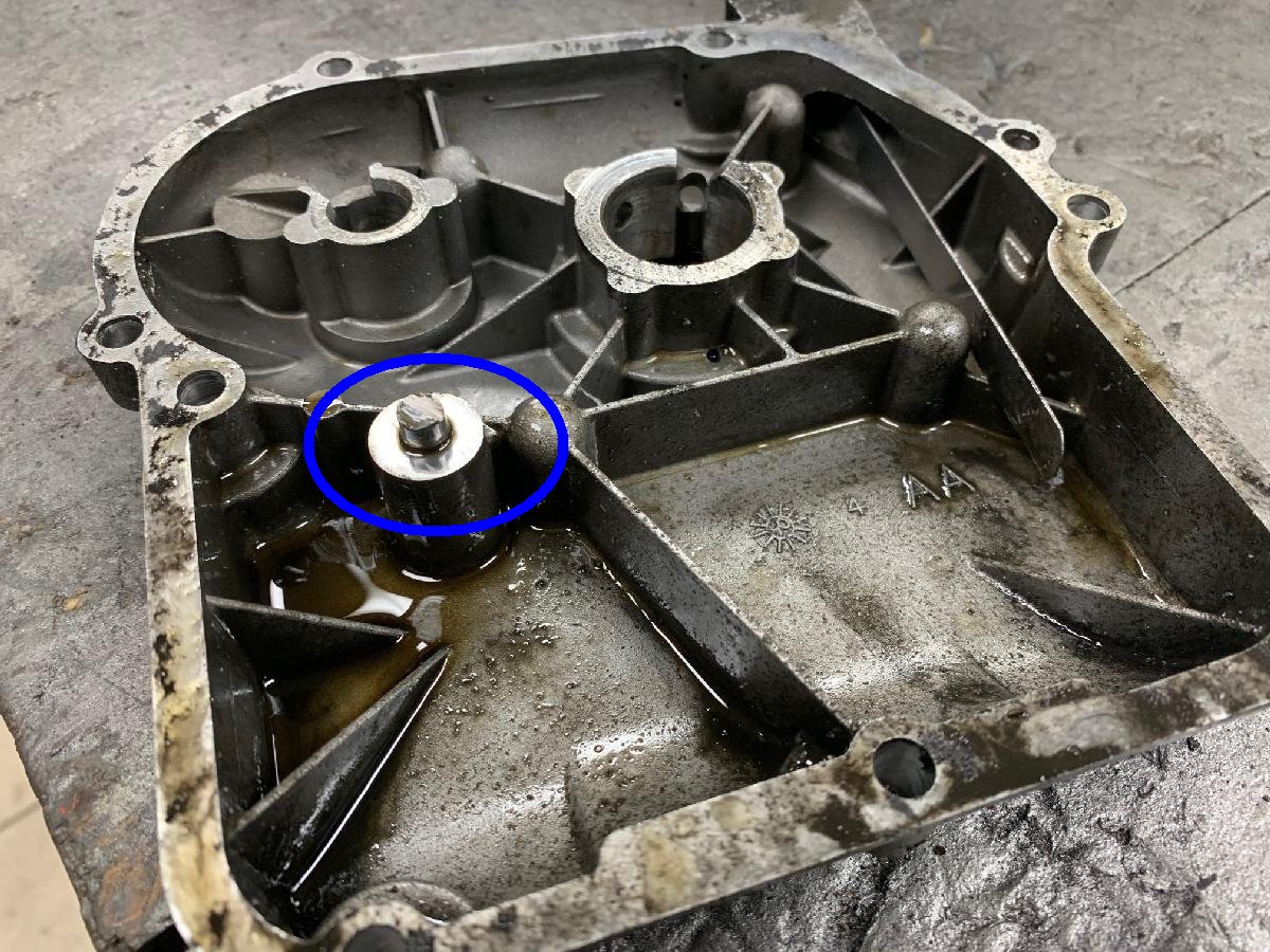
The way the governor works is as the user hits maximum RPM (3600),
internally a small plastic wheel (spool) pushes out "wings", which push on
a rod connected to the throttle arm. This backs the RPMs down by forcing the carb butterfly from full open.
This happens automatically, without any user control.
So you'll get the full 3600 RPMs at inital full throttle, but
only for a second or two. Then the motor backs
it down to about 3000 RPM (or so.) This saves the motors from
throwing the connecting rod.
-
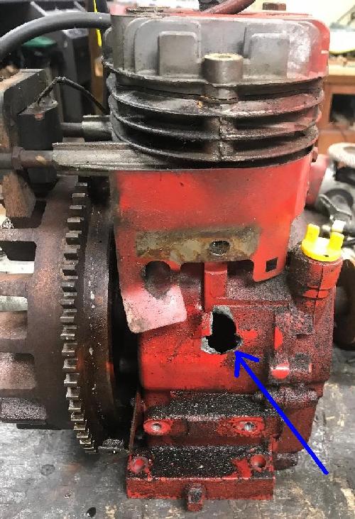
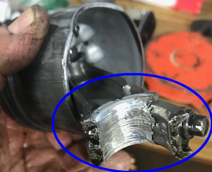
So how does the motor "throw the rod". Well the stock connecting
rod is cast aluminum, and frankly not that robust. What probably happens
is the rod's journals get starved for oil at high RPM and heats up.
It can get so hot it practically melts onto the crankshaft journal.
Then the rod seizes on the crankshaft journal, and the rod
just breaks apart... Often throwing the rod
pieces through the side of the motor's case!
-
With this in mind, do you want to remove the governor? Frankly on
my motors I always remove the governor. The internal plastic cam
and it's pieces can also break, ruining a motor. And frankly I'm
smart enough to know not to leave a motor at full RPM for extended
periods. Basically me, as the rider, is the governor! Also if you're
using a torque converter on your mindbike, it provides some level of
protection too (as the torque converter automatically changes gears,
this changes the motor load and RPM.)
-
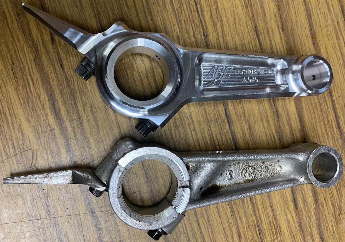
Connecting Rod Upgrade.
To really make sure you don't have connecting rod problems with no governor, consider getting an Arc #6282 billet rod. Tt really does 'bulletproof' the Tecuseh motor. The aluminum billet connecting rod from Arc #6282 is advertised for the Tecumseh OHV 5.5hp motor, but this rod works great in both vintage Tecumseh HS40 and HS50 engines. This assumes you remove the internal governor parts, as the Arc rod's oil dipper is slight different than the original HS rod oil dipper. The Arc oil dipper will hit the governor parts, so they must be removed to use this rod.
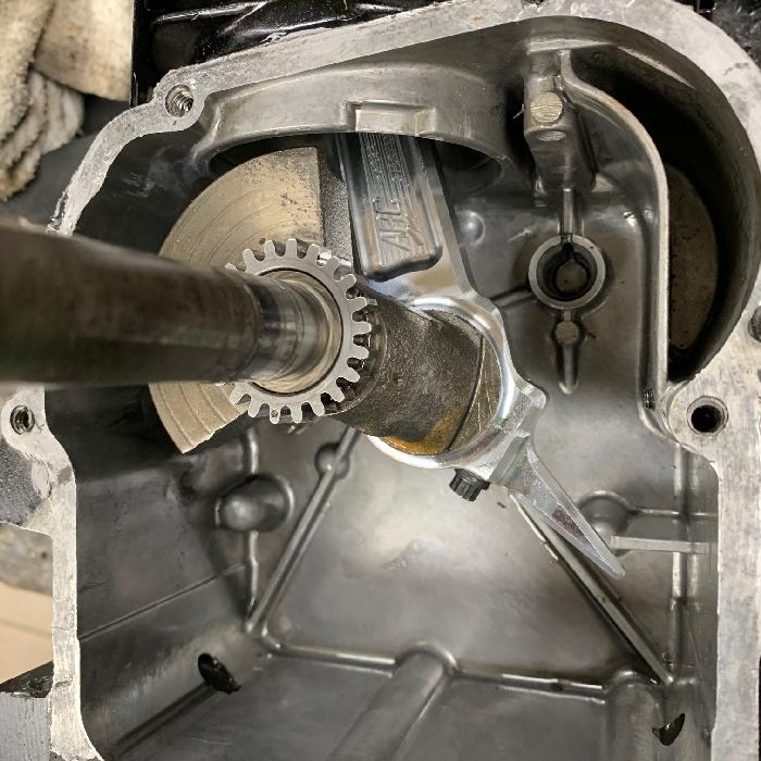
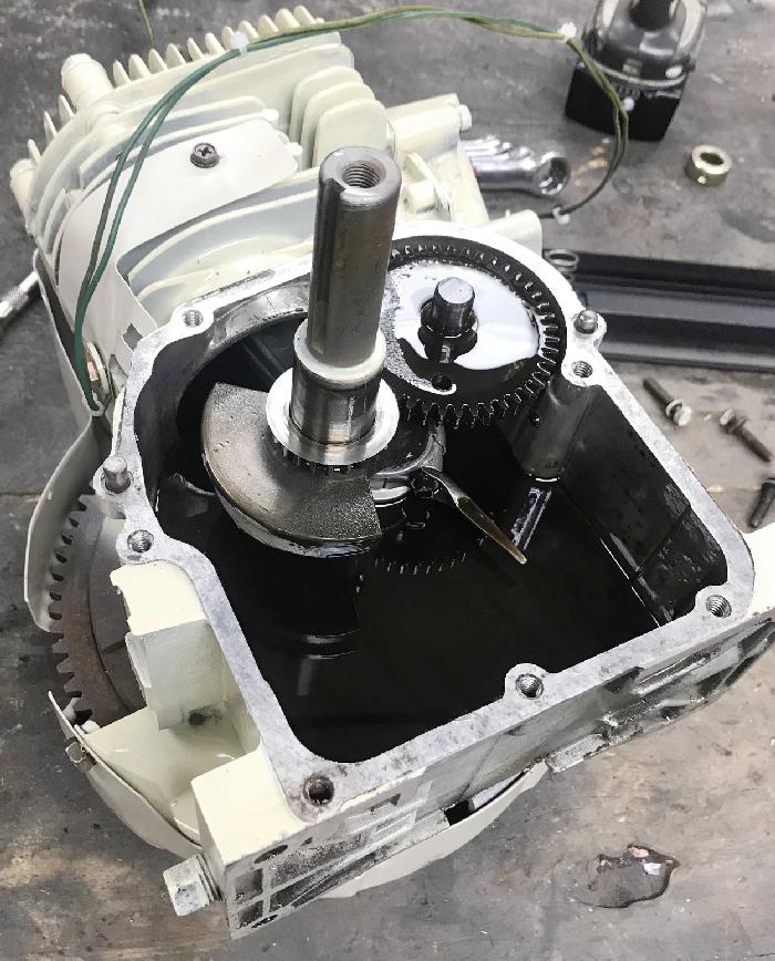
Here's an HS50 engine with an Arc 6282 rod installed. Note the governor parts have
to be removed, or the Arc rod's oil dipper will hit them!
-
From what I have seen,
the number one cause of rod failure is not enough oil to the connecting rod's bearing
surface around the crankshaft. The lack of oil at high rpm causes the aluminum to
heat up, to the point where this bearing surface can seize. If that happens, the
rod breaks.
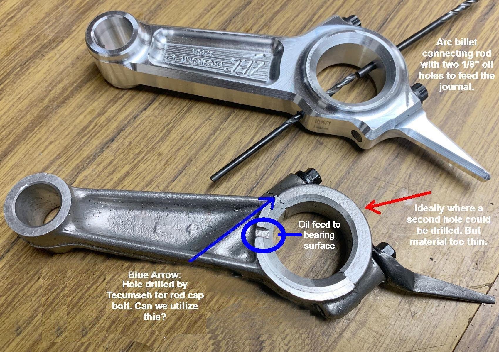
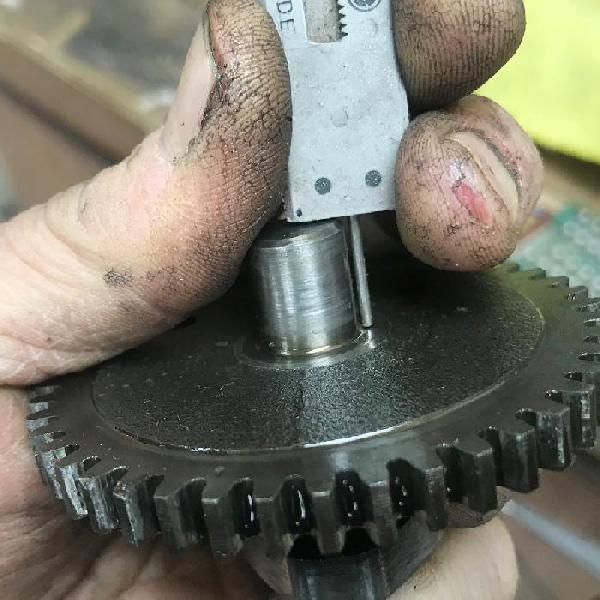
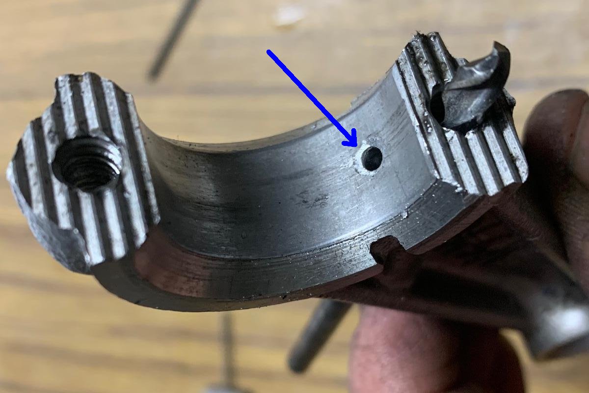
Check out the picture above. Arc uses holes to feed oil to the bearing surface. Tecumseh uses a small "port" to get oil to the bear surface. But what if we make a modification to the stock Tecumseh rod? There's already a hole in the stock Tecumseh rod that goes to one of the rod cap bolts. Why not drill a hole to connect the bearing surface to this hole? This gives another way for oil to get to the bearing surface.
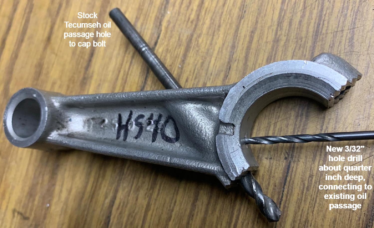
What I have been experiementing with is drilling a 3/32" hole, from the rod journal, to the hole that Tecumseh put in the rod for the rod cap bolt. The hole only needs to be about 1/4" deep to connect. It does not seem to effect the rod's strength (especially since you're drilling into the meatiest part of the rod.) And it gives another path for oil to get to the bearing surface. My idea is this will keep oil on the bearing surface at higher RPM, when a stock rod fails to feed enough oil.
So does this modification work? Well I've done it on about ten engines. Haven't blown one up yet, but that's not really a good test. A better test would be two engines (one mod'ed, one stock), in the same condition, and running the same oil. Run them next to each other at the same rpm's for the same time, and see where they seize. But I'm not doing that... sorry.
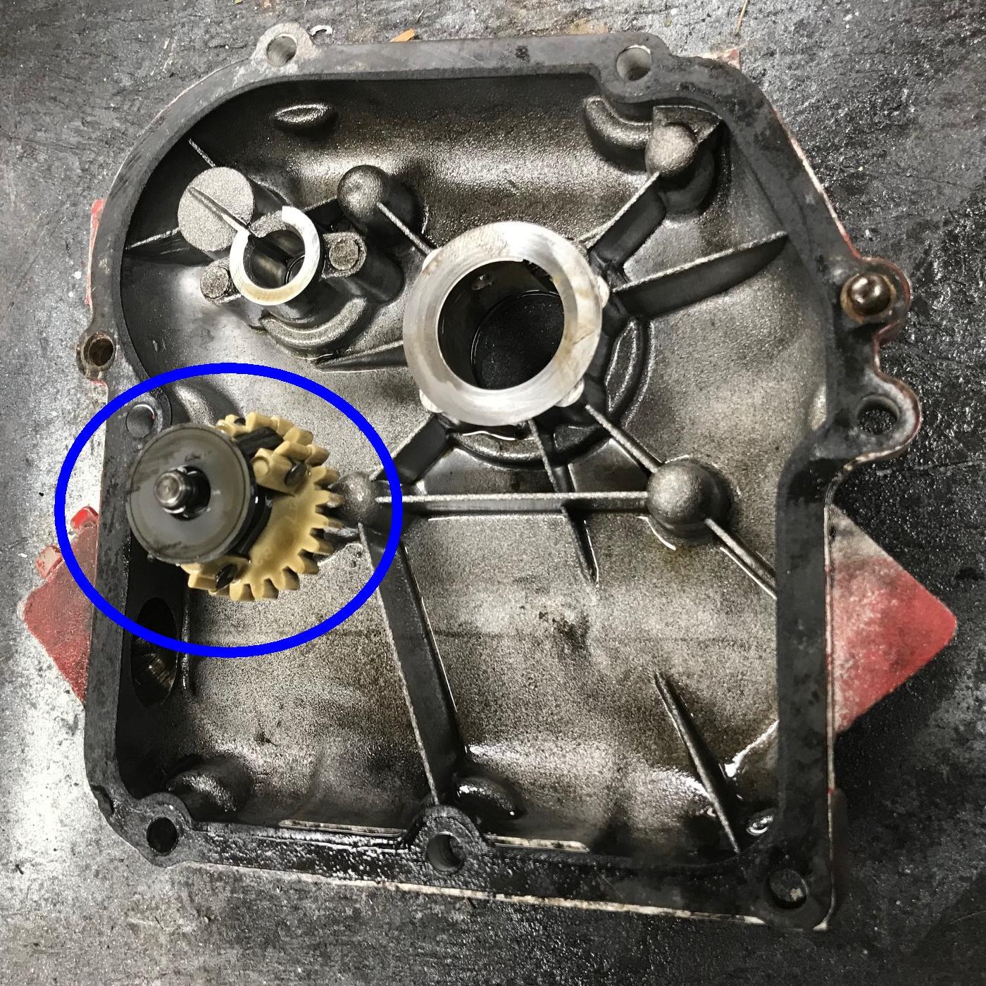
Removing the Governor.
If you are going to remove the governor, you will have to "split the case."
Frankly I don't even remove the oil to do this. Just put the motor on its
side (flywheel down), and remove the side case screws. Then gently tap the side case with
a rubber mallet, and the case should slide off (assuming the the motor
does not have a crank ball bearing on the side case, which snowblowers do not use.)
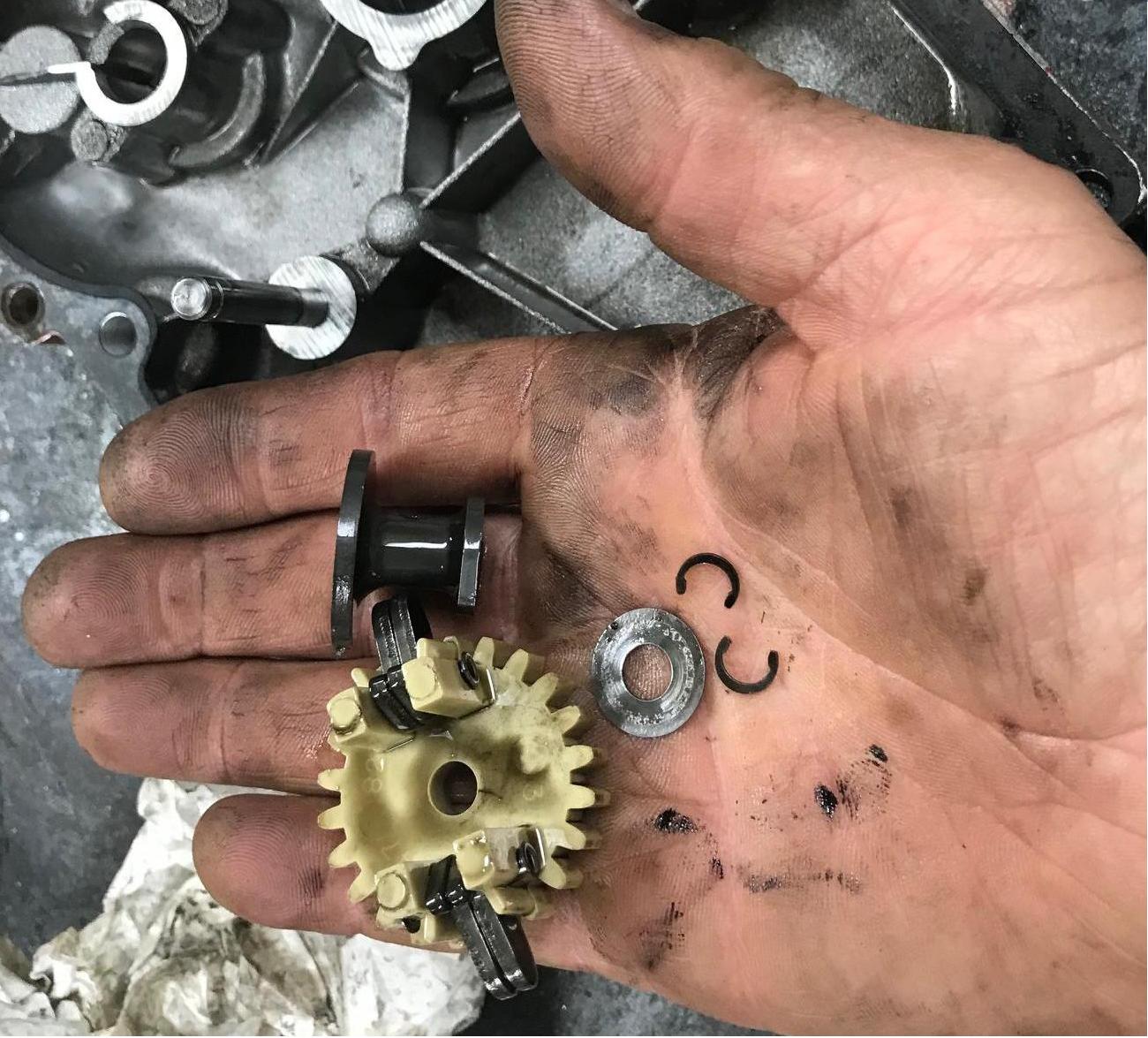
Then the parts can be removed from the side case (as shown in the above picture.)
It's just two E clips to remove the parts. Also don't forget to remove the
thin washer after the gears are removed! Note on newer Tecumseh motors (especially HSSK50 models),
the governor parts have to be cut off (they pressed on the parts and don't
use E clips.)
-
When replacing the side cover, always use a new gasket #27677. Scrap the old one off with
a razor blade. One thing I really hate is leaking engines. So I clean both the engine
and side cover gasket area with Naptha, and apply a very thin coat of Permatex Ultra Gray gasket maker.
I use a thin layer of the Permatex Ultra Gray on both the engine and side cover faces.
Then put the gasket on the engine, and replace the side cover. But don't screw it down
just yet. Just push the cover on, and let it dry for an hour. Then screw the side sump cover down
to 115 inch/pounds or 9.5 foot/pounds.
-
I have seen some people use the Permatex gasket maker with no gasket. Personally
I'm not comfortable doing that, but I have seen it. I perfer to use a new
gasket #27677 and the Permatec. I've found that to work best.
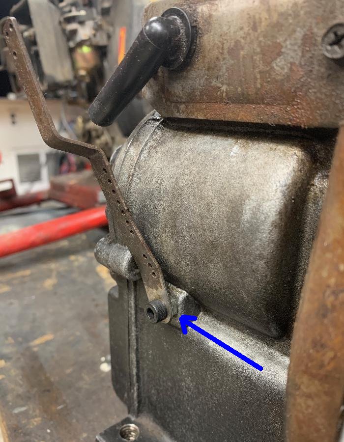
If you removed the governor system, and tap the case hole with a 10-32 bolt 3/4" long,
you can still use the original exterior governor lever arm and minibike throttle assembly #730136a,
with an original Tecumseh carb. All I do is use the 10-32 bolt with a nut, and
the original exterior governor lever, as seen below.
-
Additionally I remove the internal governor L metal arm and external throttle
arm. If I'm using a non-stock slide carb, I don't need the throttle arm.
When removing the internal governor L arm, be aware on the inside of the case there
is a small washer on the arm. Don't let the washer fall inside the case and lose it!
(Though using a magnet can often find it.)
Removing the internal governor L arm and external throttle arm is ideal. In this case
tap the hole where the governor arm was located with a 10-32 tap, and put
a 3/4" long 10-32 allen bolt and washer into the hole (from the outside) to plug it. One less
spot for oil to leak! If you are using the stock carburetor
set up, you can still remove the governor L arm. Just use the 10-32 bolt and
a nut to be the pivot point for the exterior governor arm.
-
If you are really worried about "throwing a rod" on your non-governed Tecumseh,
consider using a billet aluminum connecting rod. At $65 for the
Arc #6282
rod, it's good piece of mind. The rod is 3.484" Tecumseh 5.5 OHV Stock Length with a solid dipper.
Designed for the Tecumseh overhead value 5.5hp motor, it happens to work just fine in vintage
Tecumseh HS40 and HS50 motors.
Yes you will have to remove the piston from the motor and
do some work to install the rod. But if you already have the case split, it's not
a huge job.
-
Now and then you many have to replace the seals that go on the side case
(or behind the magneto on the other side of the motor.) Also you will need
a new side cover gasket #27677. The side cover should use a torque wrench
and the bolts tightened to 115 inch/pounds or 9.5 foot/pounds.
Here's some other part numbers that may be useful:
- Bushing side case seal: #27897 (typical of a snowblower motor)
- Ball bearing side case seal: #28540 (as used on Rupp Tecumseh motors)
- Side case ball bearing (as used on Rupp Tecumseh motors): #28458
- Magneto side case seal: #32600 (or #27876 ?)
- Side case (sump) gasket: #27677
Also don't forget if you have a ball bearing side case motor (like say a Rupp HS40 or a pre-1975 HS50 motor), you will definitely need a new side case seal #28540. That's because you have to pry out the original seal to expose a "C" clip, and remove the "C" clip, before the side case will come off the motor.
10. Getting the Color Off and Back On.
-
Let's say you're going the standard minibike color (white or black.)
But the motor you have is not that color. How do you handle this?
Well the motor can be repainted. Since you have the motor tore down
to the long block, all the metal pieces can be easily painted. But keep
in mind that you need to use a gasoline resistant paint! Otherwise just
one gas spill, and the paoint comes off your motor!
To get around this problem, I prefer to use powdercoat. As part of the process they will sandblast the parts. And the finished product looks great, and is completely gasoline resistant. On color, personally I don't use "pure white" or any glossy colors. Why? Because they are higher maintenance. Gloss colors are really hard to keep looking good, and show scratches and defects and dirt very clearly. For this reason I use an off-white matt color and medium black (not gloss black.) Lots of people do use the 'bright white' or gloss colors. But personally I just don't like that look. Also most paints are not gasoline resistant. If you're using something unknown, the SEM 1k clear in a can works well as a good gloss sealer.
-
What about that Primer bulb on the blower housing (above the pull start)?
For a minibike, the primer bulb goes away. It will pull off or unscrew.
Discard it, we won't be using it.
I guess you can leave the primer bulb hole(s), but personally I try and plug the hole(s).
Using a TIG welder I can usually pull this off without distorting
the blower housing metal (it can be a bit tough to do.) This is obviously optional,
but is a nice touch. We won't be needing that primer bulb, so plugging the
hole is ideal. After welding it shut, use a flap grinder and then
sandpaper to make it smooth. Obviously do this before paint or powdercoat!
-
So fine, you have decided to powdercoat the removable metal. But what about the block?
Obviously you can't powdercoat that! For me, I put the motor at top dead center and
block the exhaust and intake ports (and breather) with rags. Then I sandblast the long block! This gets
the old color off (important if you bought an orange motor!) When done, blow off
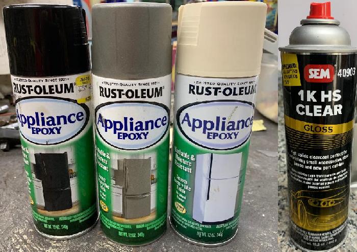
the motor with compressed air. Then I use a Home Depot available spray can product
to paint the long block. This paint is "Rust-Oleum Appliance Epoxy" paint. It's
available in white, almond, black and silver (though silver I had to order online.)
I like the almond color for my white engines
(the white color is "too white" for me). If you let this spray paint dry for 48 hours,
it's really gas resistant. More resistant than other paints I have found (short
of spraying 2-part urethane.)
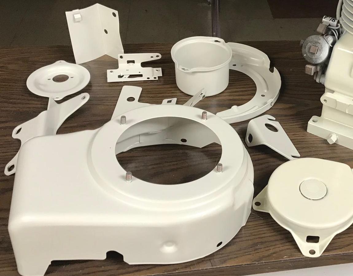
Using the appliance epoxy spray paint on an HS50 engine for a MTD minibike.
The blower housing was also painted and then cleared with the SEM 1k.
-
After letting the long block paint dry, don't re-assemble the blower housing parts. Because the next
thing we have to address is...
11. Replacing Points Condenser, Flywheel Removal, Kill switch, Lighting.
-
If you have an older motor, now is the time to deal with the points and condenser.
If you have a newer motor with electronic ignition, skip this step. Note we
are doing this after we blasted and painted the long block.
Adjusting the CDI coil is pretty easy. Just loosen the two screws that hold it,
put a business carb between the bottom of the coil and the top of the fly wheel
magnets, and tighten the coil mounting screws. This is known as the "airgap".
Officially the airgap should be .0125", but most people don't have a feeler gauge
that exact thickness. Therefore the business card trick is used. Now are most
business cards .0125" thick? Probably not... but it seems to work just fine
doing it this way.
-
Since you already have the blower housing off, you can see the flywheel.
This will need to be removed to access the points/condenser. Remove the
center nut first. Some guys have luck using a rubber mallet and hitting
the crankshaft end (where the nut was remove) to "pop" the flywheel. Personally
I've never had luck doing that. And I've seen people ruin the crankshaft
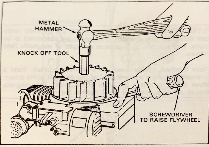
threads. Some people back off the nut and hit that. Again, don't do it... the
nut is too small and too thin. Tecumseh sells a device (knock off tool) to do this, part #670103 (for small nut
older flywheels) or #670169 (for CDI large nut flywheels).
Basically it's a huge long nut that goes on the shaft to allow this technique.
Use a stiff plastic mallet and hit the flywheel knock off tool #670103 or #670169 (where the flywheel nut was removed),
while using a screwdriver to push behind the flywheel. Again, I've not had much
luck doing this, but others have. Tecumseh recommends this technique in their repair manual
-
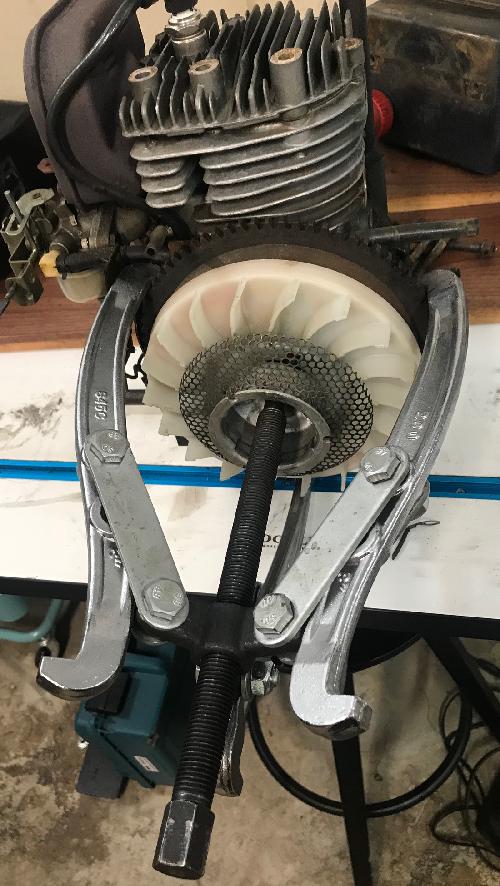
For this reason I bought a 3 leg flywheel
puller off ebay for $20. But be warned, a jaw type flywheel puller can crack the
flywheel. This is not really an issue with a steel (cast iron) flywheel (as used on
snowblowers and most Tecumseh engines after 1975). In particular if your cast iron
flywheel has an electric start gear, this works really well.
But if you are working on a minibike Tecumseh or very early Tecumseh with an
alloy flywheel, you can crack a flywheel using a jaw type puller. So don't do it!
-
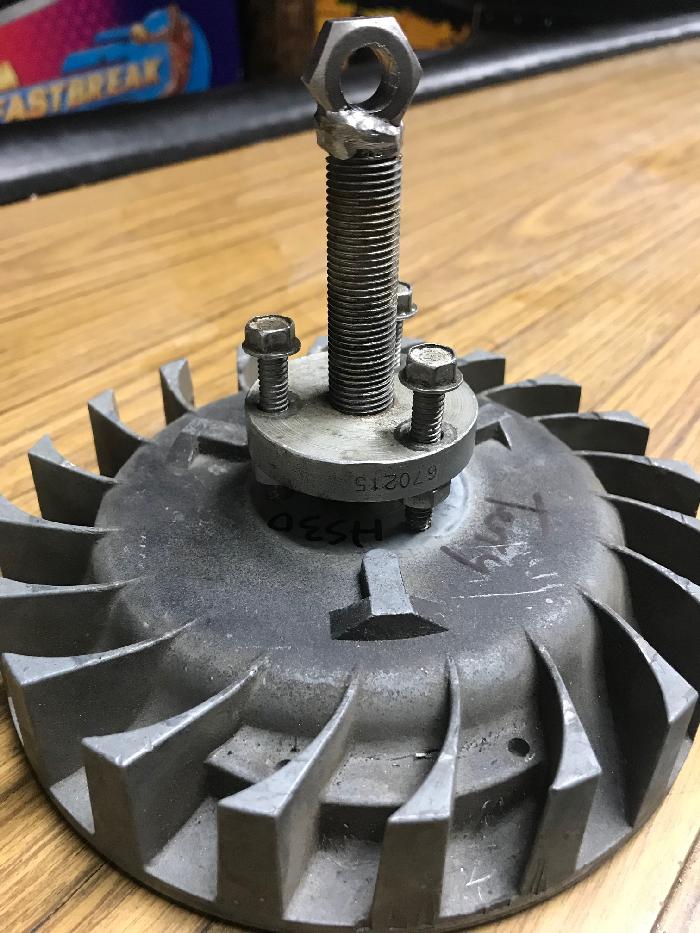
If you have an alloy flywheel, you must get the proper flywheel puller.
That would be Tecumseh part #670215 (or some alternatives like #670306, #670218, #25183.)
It screws into the alloy flywheel, close
to the nut. This works really well and won't crack an alloy flywheel. I can't
stress how important it is to do this correctly. If you use a 3-leg flywheel
puller, it's pretty much guaranteed you'll distort or crack an alloy flywheel!
-
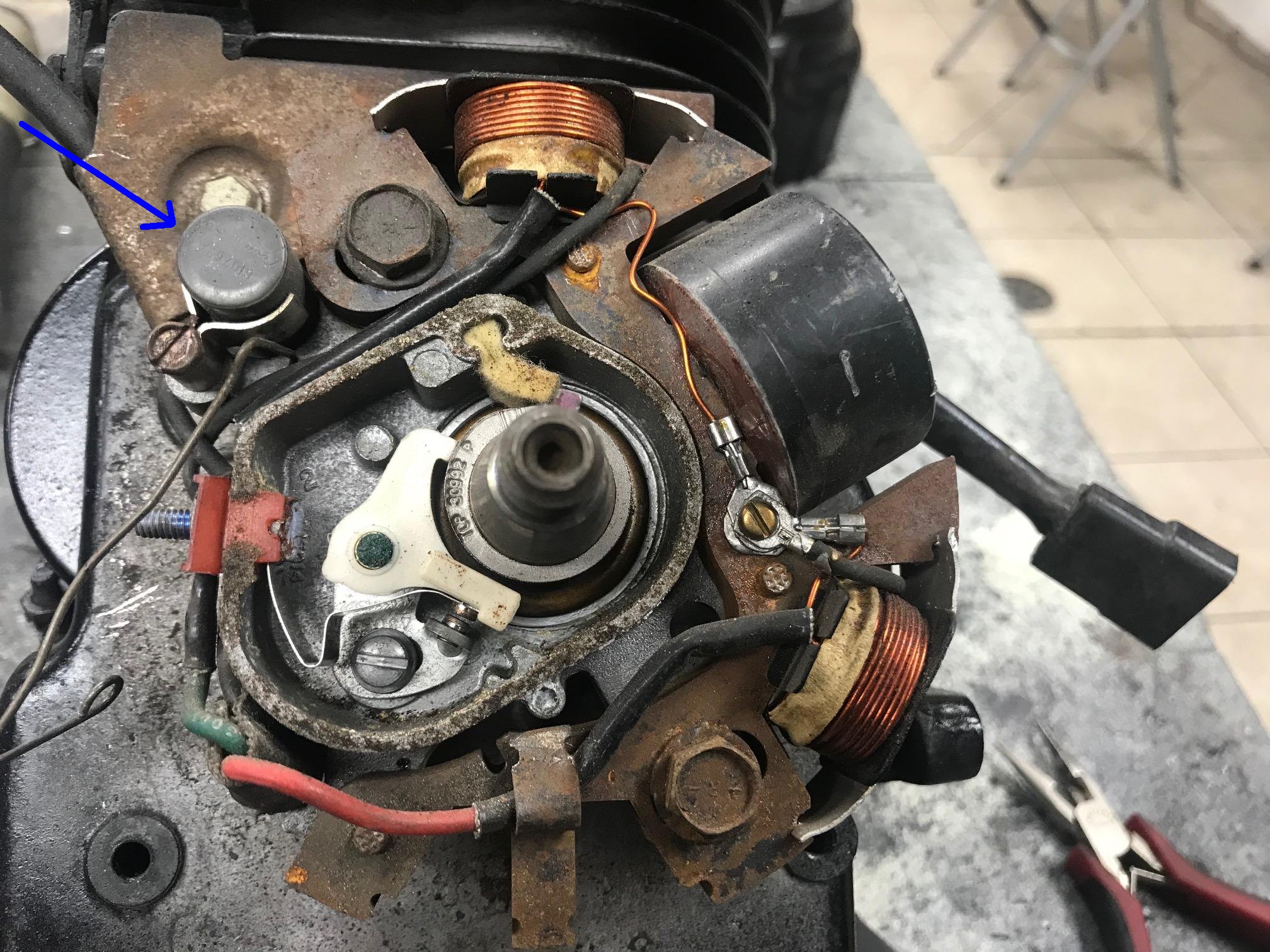
With the flywheel off, you can see the coil and (covered) points
and condenser. First off, just replace the consender #30548b. Don't mess
around, it's a $5 part, just install a new one. I also take a
Sharpie and write the date on the top of the condenser. It's easy
to replace this part, it's one screw to hold it in place, and
then the nut where the wires all connect (on the points.) Don't
replace that nut just yet, we'll need it off to service the points.
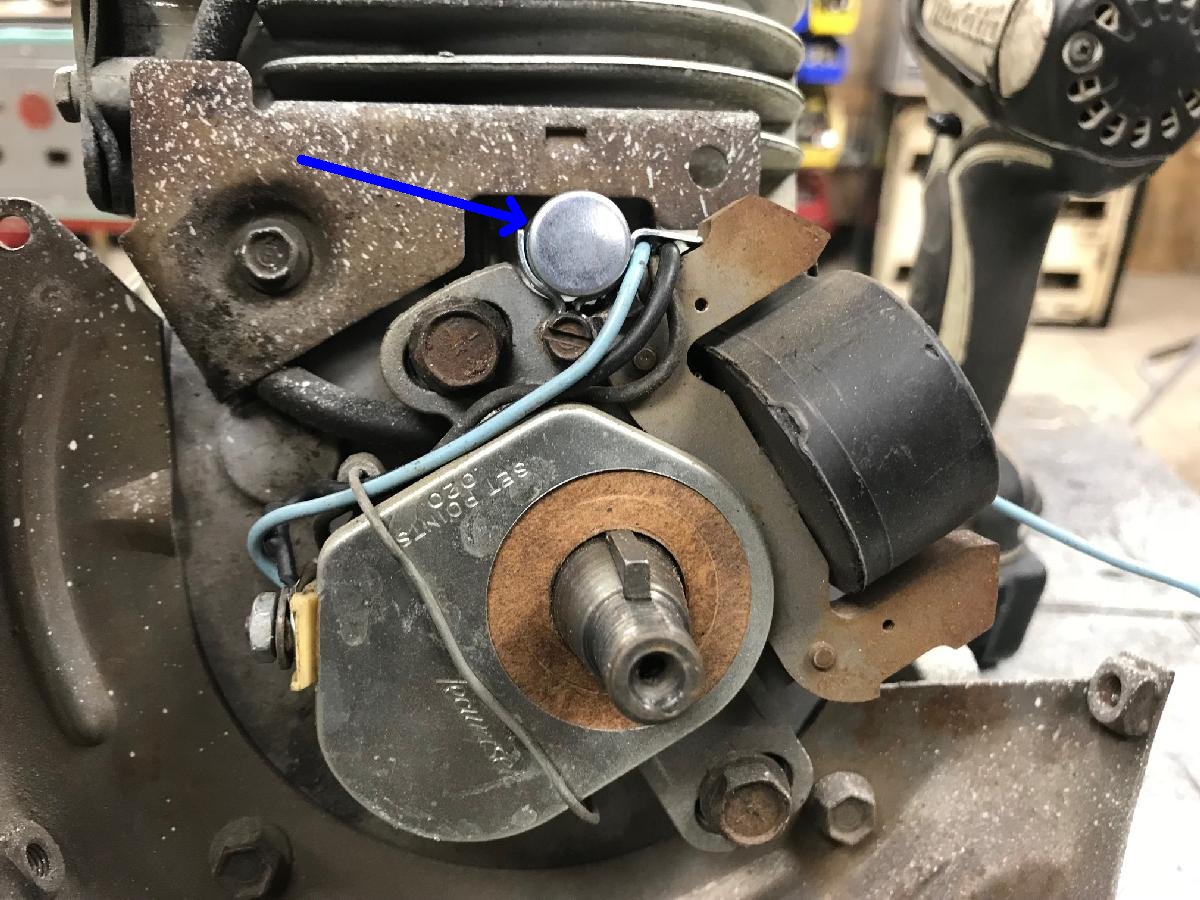
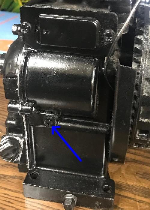
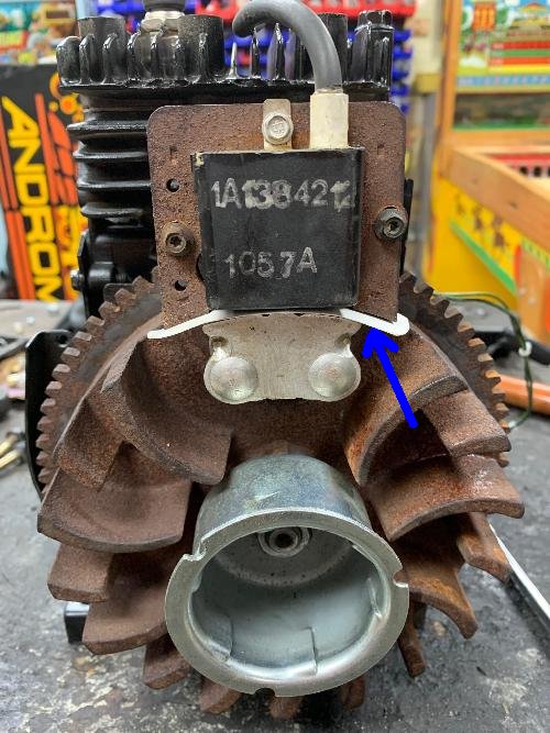
Working on a minibike Tecumseh with lights? Then the magneto is slightly
different (to power the bike's lights.) Here's a Rupp style magneto (coil).
It's really the same, but the condenser is in a slightly different location.
The blue arrow shows the condenser #30548.
-
Next remove the aluminum sheild that covers the points. It's just a spring
clip that holds the cover in place, easy to remove with a small plyer.
Then you can see the points. Rotate the engine's PTO shaft to TDC (top dead center).
That's with the shaft's key straight up at 12 oclock. Also there's usually
an arrow or other mark on the point riser colar showing TDC. When the PTO
at TDC, the points should be gapped at .020". Don't worry about that right
this second... Just use a flathead screwdriver and remove the screw that
holds the points in place. Also pry the wire bolt out, and the points will
be completely removed from the magneto.
-
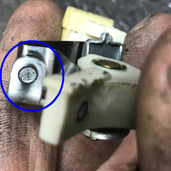
With the points removed, you can examine the actual points. They are probably
pitted (unless they are new.) That's why we are replacing them. Note the pitting
is exaggerated by a bad condenser. In fact, that's the condenser's only job,
to save the points from pitting (the engine will work without the condenser,
but the points will pit severely, and fail.) The condenser is essentially
an electronic shock absorber, preventing arcing across the points (which
causes the points to pit and lowers the voltage at the spark plug.) For this
reason you should always replace the condenser when the flywheel is removed.
Anyway, the points are part #30547a, and new ones
can be purchased for about $10. Alternatively you can re-face the original
points to remove the pitting. It's your choice, either way works fine.
Personally I like to re-face the original points myself.
Remember, when installing new points, you need to clean them before installing. There will be a protective coating over the face of the points. I use some 600 grit sand paper to do this. Just close the points with the sand paper between them, and pull the paper out. Make sure you get both sides of the points. This will make sure your new points work as they should.
-
Now install the new (or re-faced) points. A lot of companies (other than Tecumseh)
made replacement points. My suggestion is to use 'real' Tecumseh brand points
if you're replacing them. The off-brand (like say Sten) don't seem to be quite right.
Since the engine is still at the high point on the colar, adjust
the point gap at .020", and tighten the screw. When you do this the wire nut should
be tight - point gap can change if that nut is not tight. Also as you tighten the
flat head screw to set the points, sometimes they 'walk'. So re-check after you
have the adjustment flat head screw tight, to make sure it's still at .020" gap.
You may now install the aluminum cover #30550 (or #610947) and it's gasket #610948. Usually the cover and its gasket will be in fine condition and can be re-used.
Now you may replace the wires on the points screw. The nut should have been tigthened when you adjusted the points, so remove it and install the wires (assuming that was not done before). I add a 3 foot length of wire (light blue wire in the pictures) to this screw/nut too. This is the kill switch wire! I like all my minibikes to have a handlebar mounted kill switch, and you'll need a wire to ground out the points. I use #18 or #20 gauge stranded wire for this. This is very important to do, since you have the entire motor already apart! Alternatively you can use a spark plug shorting clip #30747. But personally I hate those things.

-
How the wires are run around the magneto is very important! If you get this wrong,
the flywheel can rip or fray the wires, killing the engine. The wires run under the
point cover retaining clip. They also run underneath the condenser "leg". Get this right!!
Finally if the flywheel key #610961 was removed, note it's orientation - the notch goes towards
the center of the engine. With this finished, you can replace the flywheel and tighten
the flywheel retaining nut. This nut must be pretty darn tight! Otherwise the flywheel
can become loose, and shear the flywheel key. This will change the timing,
and the motor will never run. If you have a torque wrench, tighten the flywheel nut
to about 50 foot/pounds. Not a good idea to use an impact driver to tighten the flywheel,
it can over-stresses the flywheel and crack it.
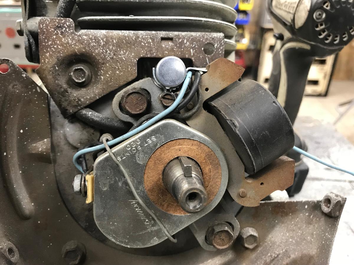
For the last few years of the points/condenser models, Tecumseh started to
wire their points and condenser a bit differently. Below is the more "modern"
version of how they ran the wiring from the condenser to the points' bolt.
Either way works, but I stay with how the motor was originally wired.
NOTE the red arrows in the picture below. DO NOT remove these bolts! They
adjust the timing, and there's no reason to do this (assuming you do not
remove those two bolts!)
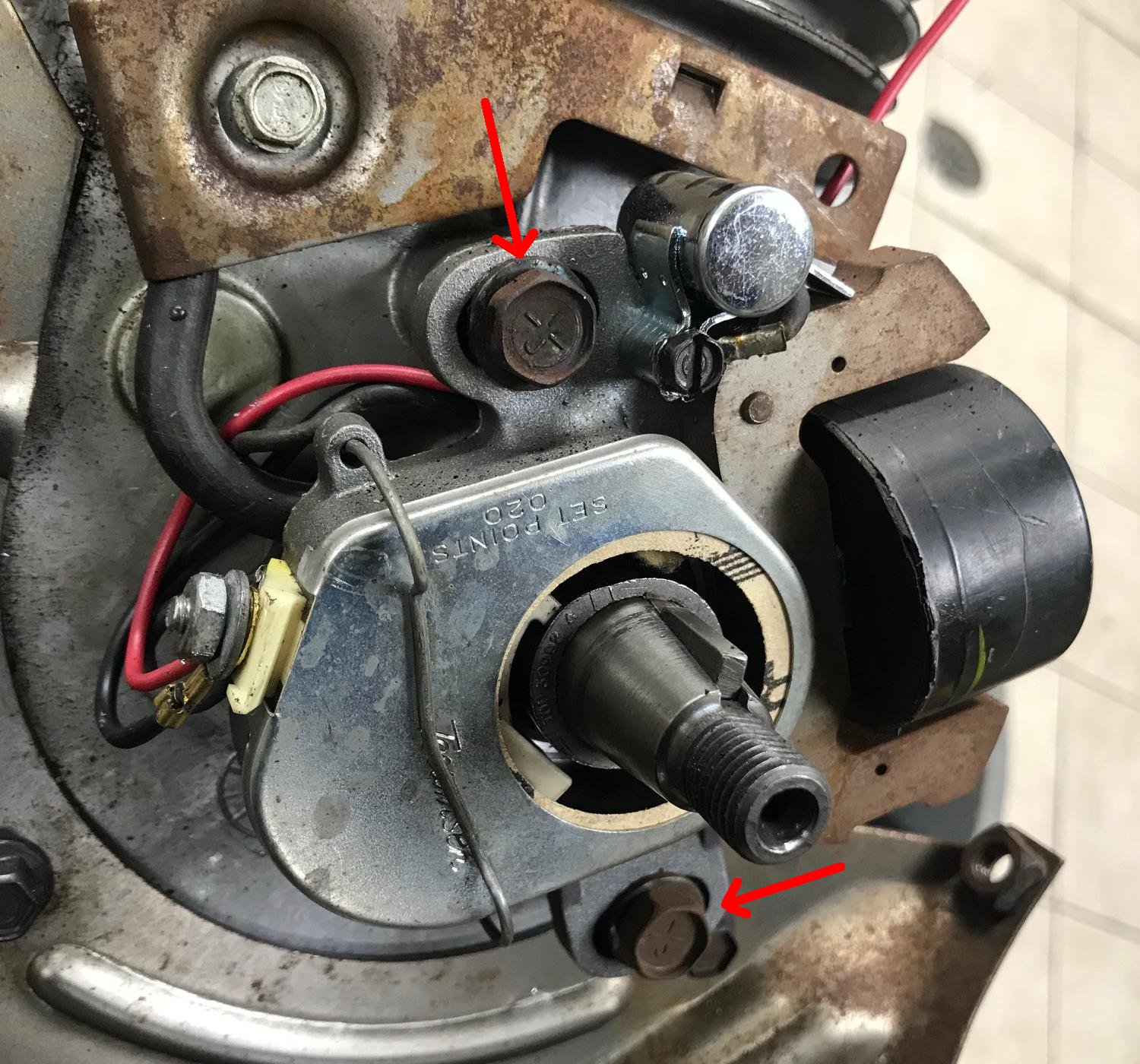
-
Setting the Timing is a trick on these engines. The CDI motors don't
allow you to change the timing, so those are really easy! There's nothing
to do, other than set the distance between the magnet and the coil,
aka the "airgap". The official airgap distance is .0125", but most
people just use a business card, as seen above a few screens.
(Though it should be noted that a business card is generally not
.0125" thick, but it does work as having a long feeler gauge
that is .0125" thick is pretty hard to come by!)
On HS40/HS50 points motors, the timing can be set to .035" BTDC
(before top dead center). My suggestion is this.... don't mess with it!
There's NO reason to remove the magneto in the first place (it's held
in place with two 1/4-20 bolts.) Hopefully you didn't remove these.
Because adjusting the timing requires a dial indicator and an ohm meter, and some work.
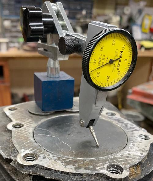
-
Basically you set the points gap to .020", and then
adjust the piston to .035" BTDC (for an HS40/HS50). Now adjust the magneto frame (stator plate) to just
open the points there (using an ohm meter.)
It's just not worth doing unless you removed the magneto - and even if
you did do that, usually you can put the magneto back and adjust it to
the old 'witness marks' from the bolts. That will get you pretty much perfect correct.
Note that the smaller engines like the H30 have a different timing of .065" BTDC
(except for 1983 Tecumseh H30 engines, the last year with points, just to make it confusing!)
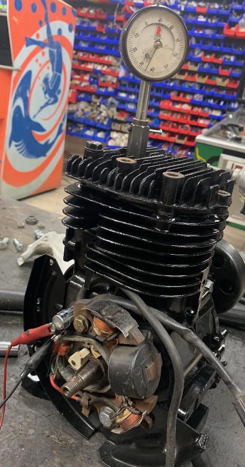
-
The easiest way to set the timing is to use the Tecumseh dial indicator that was
designed for this. It installs in the spark plug hole. Just make sure you
have the "finger" pointing towards the piston. Also sometimes the "finger" must
be bent down slightly so it doesn't hit the cylinder wall. Note I really don't
recommend messing with the timing unless the magneto was removed. It takes a good hour of
messing around to get the adjustment just right. That's because when you tighten
the two magneto bolts, the value changes. So it's a constant test and re-test until
you get it set.
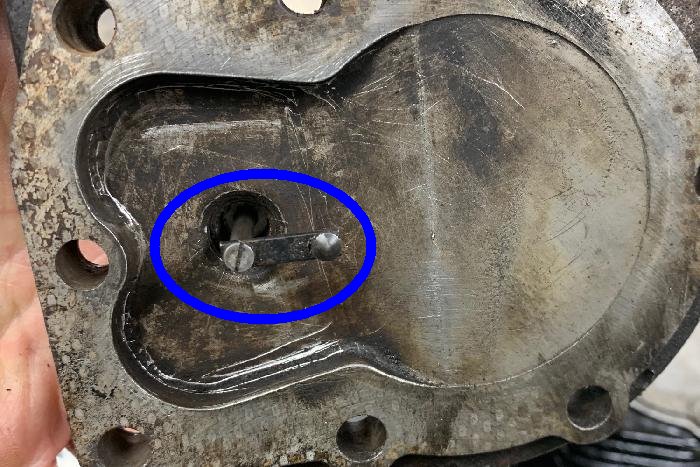
-
If you don't have a dial indicator, there is another way to set the magneto
timing using a straight edge and a .035" feeler gauge. It's not as accurate
as a dial indicator, but it really does work pretty well. Take the head off
and use a 6" straight edge across the top of the head area. When the piston
is at top dead center, there should be *no* space between the bottom of
the straight edge, and the top of the piston. And no "rock" on the straight
edge either.
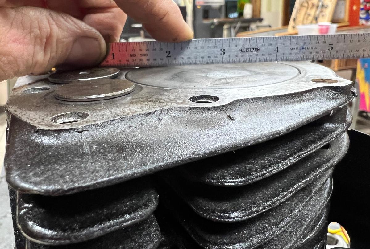
-
Now turn the crank counter clockwise (as facing the magneto) to bring the
piston down. Put a .035" feeler gauge on the top of the piston, and raise
the piston to just meet the bottom of the straight edge. Now the piston is at
.035" before top dead center (BTDC.)
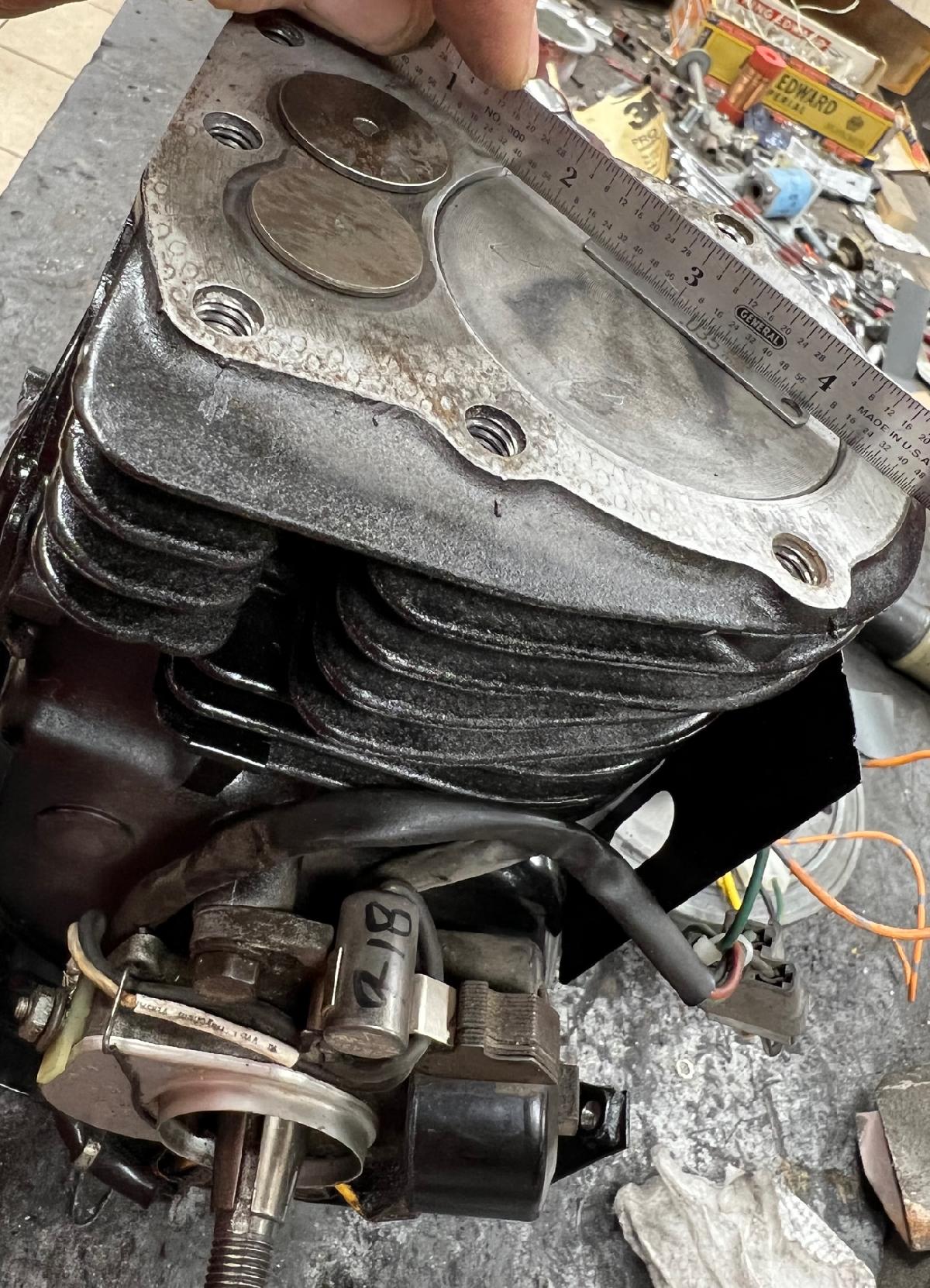
-
Using a DMM meter set to low ohm/tone (one lead on ground, the other
on the points wire attachment nut), and all the wires off the points
attachment nut, rotate the magneto frame to get it to just make "tone"
with your meter. This sets to the magneto to .035" BTDC. Tighten
the magneto adjustment bolts. This accomplishes the same thing as
a dial indicator to set the timing at nearly the same accuracy.
Since you installed a kill switch wire on the points, I also suggest running a hard ground wire with the kill switch wire. Though technically the engine's frame is grounded through the entire bike, if you have rubber mounted handlebars, that ground may not work. So have a discrete hard ground is recommended. I mount that wire directly to an engine bolt (see picture below.) Then I used a two wire kill switch like the one used on the modern-ish DB30 (these are available on ebay for $5.)
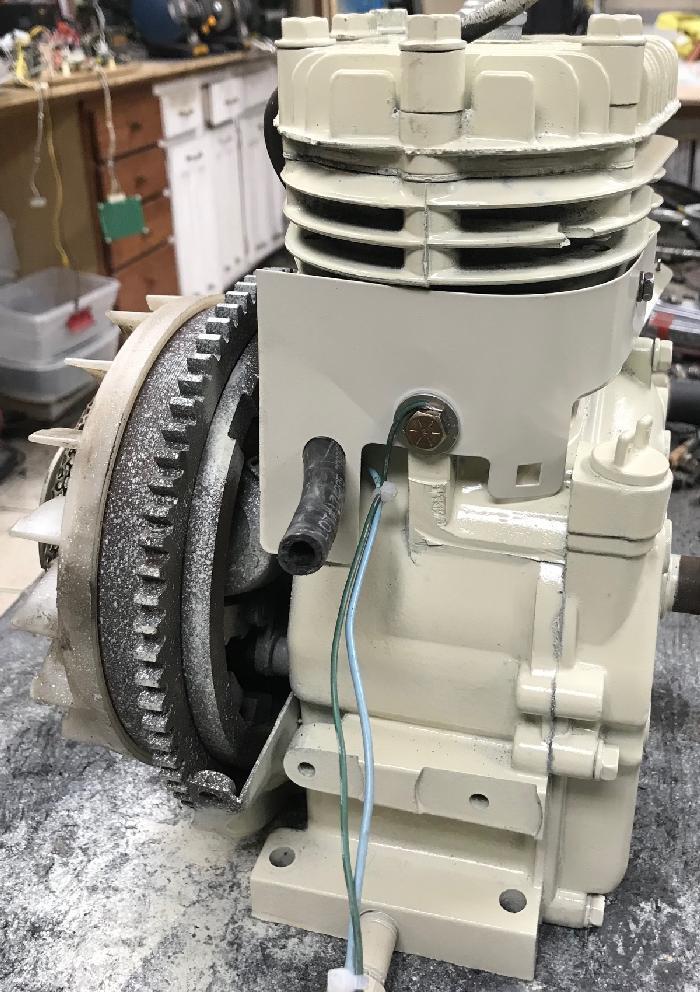
-
One important note... In the picture above you can see I used the bolt that
holds the engine sheild as the ground point. This bolt is a 1/4-20 style
bolt, and it's not very long (1/2" long). DO NOT use a longer bolt than 1/2"!!
I can't stress this enough. If you use too long of a bolt, and can push
a hole into the combustion chamber. That would be a bad thing...
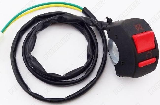
-
After the flywheel is installed, you need to check to make sure
you did everything right! Also remember to use a torque wrench
to tighten the flywheel. A steel flywheel gets 550 inch/pounds
(or 46 foot/pounds), and an alloy flywheel gets 450 inch/pounds
(or 37 foot/pounds).
The best way to check your work and check for spark is to remove the spark plug. Leave it connected and laying on the top of the head (as a ground connection), and quickly spin the flywheel (the flywheel should spin easily with the spark plug removed.) You should see a small spark across the plug. Having the shop lights off helps, but usually you can see the spark in a lit room too.
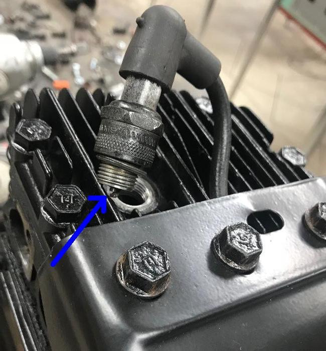
-
Another method is to use a spark testing gadget. This item is available online
and plugs into the spark plug wire, and then to ground. There's a 240 volt
light bulb inside the tester, and it will light up if there is indeed spark
(obviously you need to spin the flywheel quickly.)
Personally I like using the spark plug method better, as it's more realistic.
But this works too.
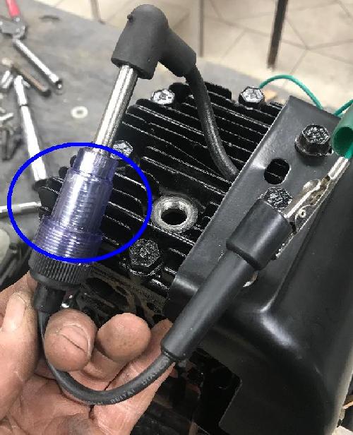
-
Another easy way to test for spark is with the flywheel attached, but
with the blower housing still removed. Handy to do before you
re-assemble the blower housing. This requires having the spark plug
removed too. Put a socket on your drill, put your drill in "forward",
and spin the crankshaft using the flywheel nut and the drill. Since
the plug is removed, you can easily see if there's spark at the plug.
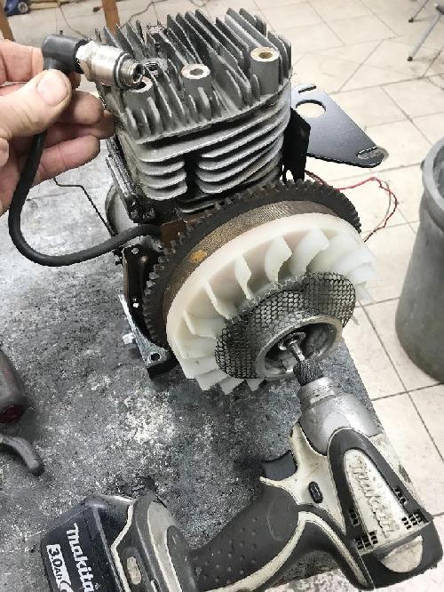
-
If you don't have spark, then obviously you did something wrong. One thing
I do too often is to have the colar that moves the points installed backwards.
If you do that the spark will never work (as the magnets on the flywheel
won't line up with the points opening.) Remember with the flywheel key at 12 oclock,
the points should be fully open.
Lighting Coil or Charging Coil Wiring.
If your Tecumseh engine originated on a Rupp, MTD, etc style minibike with
a headlight, the magneto has what is known as a "lighting coil" or "charging coil."
The flywheel is special too, with many more magnets. As the motor
spins, it supplies 12 volts AC at 3 amps to the lighting system (headlight, tail light, etc.)
These motors are considered "special", as putting a snow blower motor on
a Rupp Roadster isn't going to make the headlight work (if that's important
to you, which it may not.)
It's easy to tell if your motor has a lighting coil. There's a 3 prong plug
on the front side of the motor that is used for the lights.
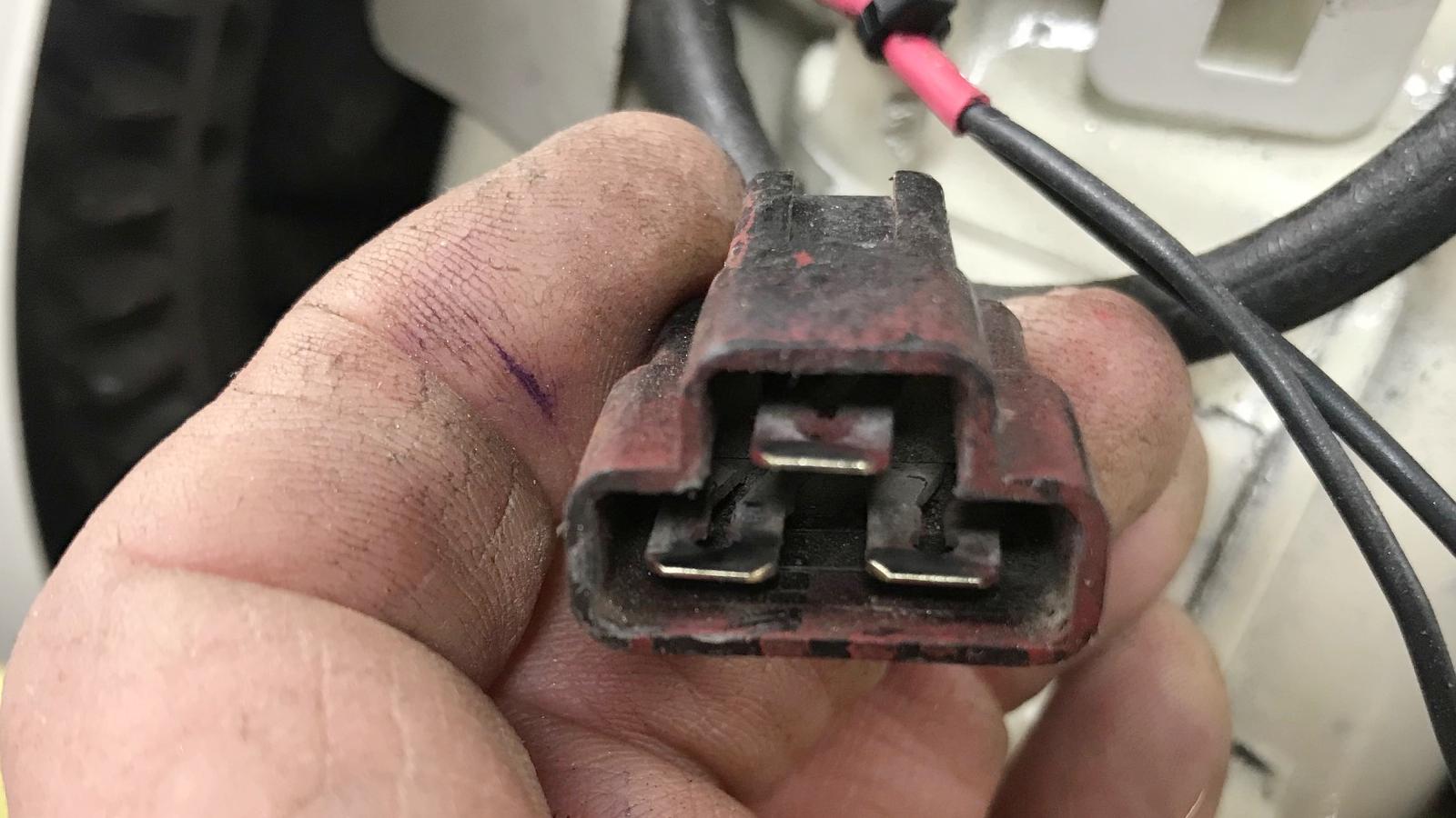
-
If you're wondering what the wiring is for this plug, as we're looking
at it in the picture above, here's the layout (note that "ground" is
just the engine casing):
- Top lug (green wire) = ignition grounding (kill switch)
- Left lug (black wire) = light power to headlight
- Right lug (red wire) = light power to tail light
Note that in the 1980s the wire color at the 3-prong plug changed. Green stayed the same, but the two power wires changed to yellow.
You can check your lighting coil on a running engine. At lower RPM (say 2500) the voltage will be lower (around 8 volts.) But as the motor revs it goes up to as much as 14 volts. You can use a volt meter and check at the plug for AC voltage. Note on bigger motors (say 10hp), where there's a battery (and the battery is charged), there will be a diode or bridge rectifier to convert the AC generated by the magneto to DC voltage. But for smaller Tecumseh 4 and 5hp engines, this is not the case.
As far as headlights go, Rupp for example in 1970-1975 used a sealed hi/lo beam lamp #4456 (hard to find and about $30). The 1969 Rupp headlight did not have hi/lo beam, and used a #4411 sealed lamp (much cheaper, about $12 and easier to find, even at your local auto parts store.)
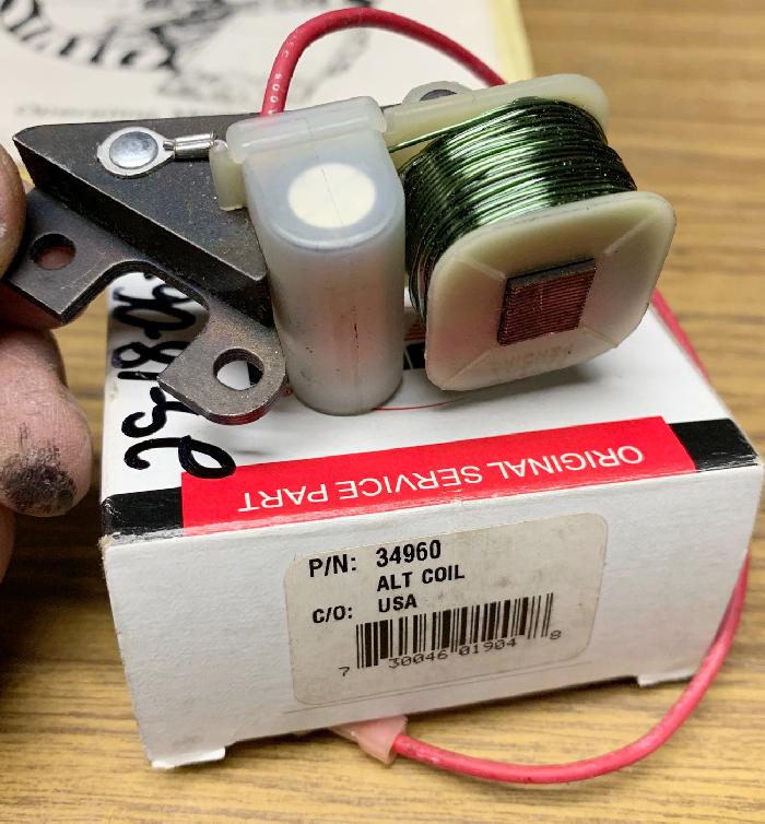
-
On CDI (solidstate) engines, lights can also be added. The least expensive way
is to get Tecumseh alternator coil #34960. It's a lighting coil that bolts on the side of
the existing CDI ignition coil. It's not really that expensive, and it doesn't require
a different flywheel either. That's the upside. But the downside is it only
provides 350ma of power (compared to 3amps for the points lighting coil version.)
Why is that? Because there's no additional magnets on the flywheel.
This device is really designed just for charging a 12 volt battery.
But to be honest, it works great (as long as you use an LED headlight.)
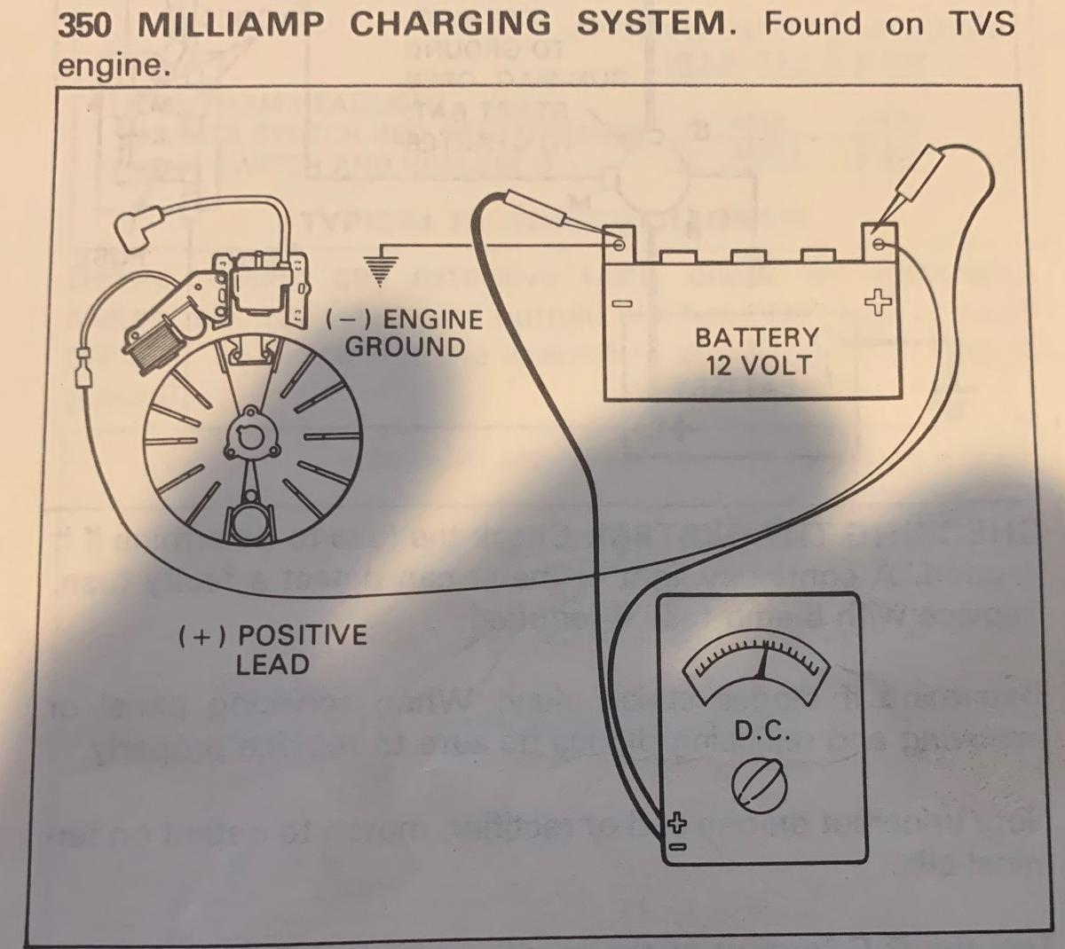
-
Can you power a headlight with 350mA of power? Yes but just
an LED headlight (and LED tail light) on your mini bike. Since there's just one
magnet supplying this lighting coil, the power will not be as smooth at idle as the
points 3amp lighting coil. They use a 47mfd capacitor and 1n4004 diode to try
and smooth the power a bit, but the LED headlight will flicker at idle. Using
an LED headlamp is your only choice, since only 350mA of power is available.
But as the engine's RPMs increase the flicker goes away. It really does work well
with an LED headlight. But you need to add a 25 ohm current limiting resistor to the
LED head light too. Why is that? Because this device will power more than 12 volts
when the RPMs are high, and this will kill an LED light. So using a 25 ohm resistor
will prevent the LED headlight from getting over voltage and dying.
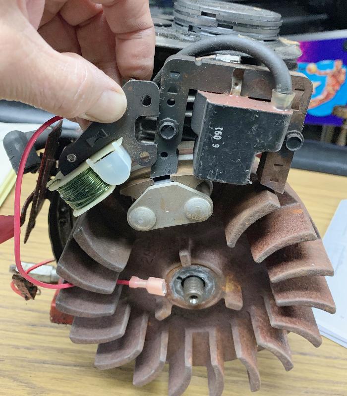
Have found the Krator 6" LED headlight to work quite well with the Tecumseh #34960 lighting coil. I drill a hole in the top of the headlight dome and put a toggle switch there. Then put the 25 ohm 5 watt resistor in line from one toggle switch lead to the head light plug. I only use the high beam lug of the LED light (ignore low beam, really what's the point?) The other lead on the LED plug goes to ground. Yes at idle it will flicker a bit. But as soon as you give the engine any gas, that problem goes away. This light is amazingly bright with this set up, and no battery is needed.
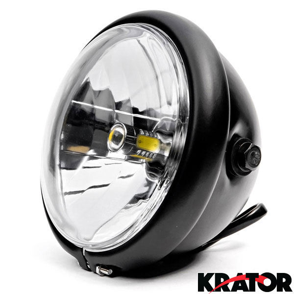
-
When using the Krator 6" LED headlight, I like to drill the body of the light
and mount a toggle switch. This way all the control is right on the light
(easier to mount, no handlebar switch needed.) I also mount the 25 ohm resistor
inside the light.
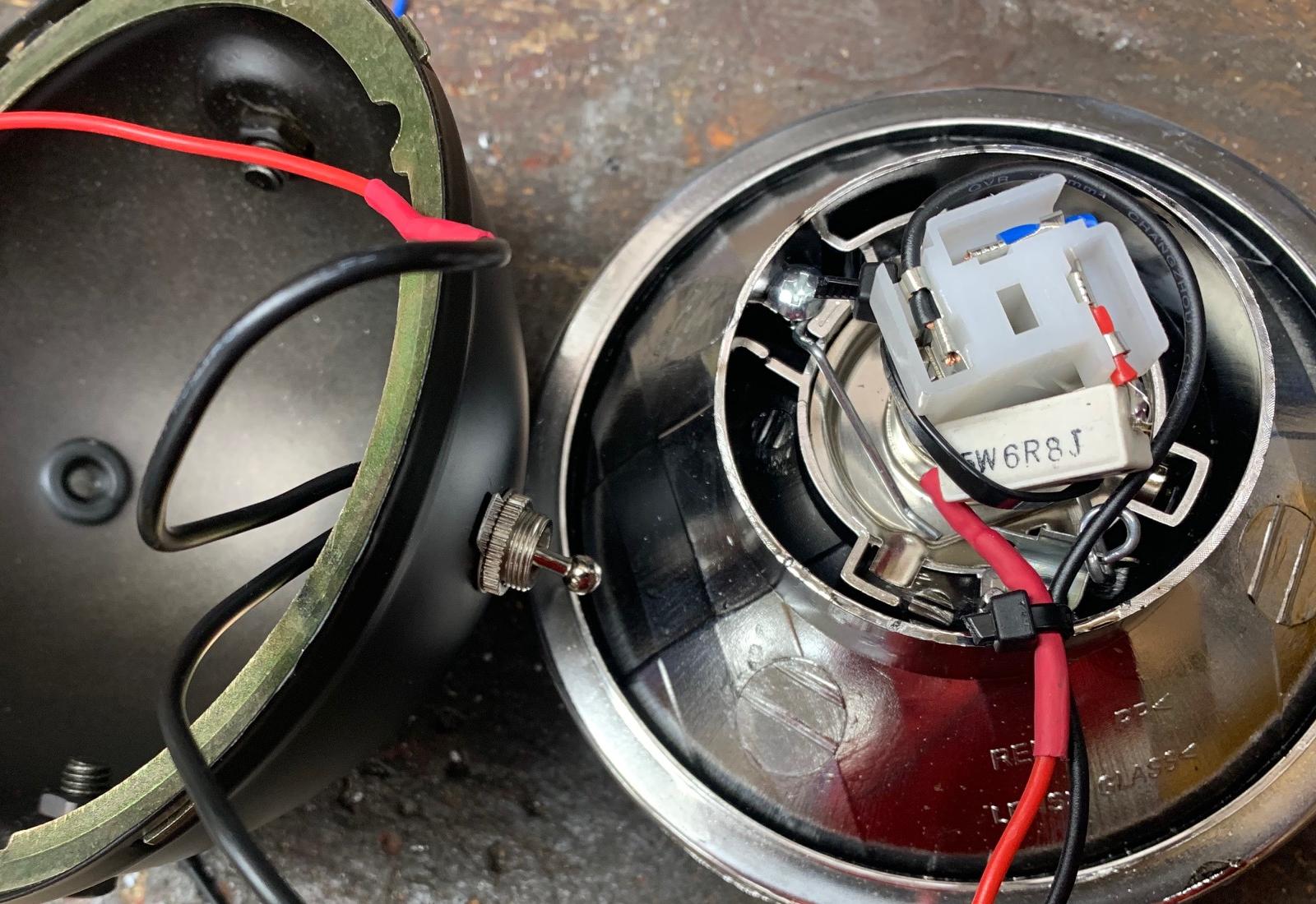
-
Other Lighting Alternator Options.
If you want more power than the 350ma inexpensive #34960 alternator listed above, for about $100 you can add a 3amp alternator. But this only works on engines with CDI ignitions (won't work on points/condenser motors), AND the block must have mounted for points. Most of the HS engines made in the 1980s have mounts for both CDI and points, and this is what you need here. The Tecumseh #611104 alternator is available for this. With the flywheel removed, it bolts where a points/condenser magneto unit would go, but it provides power for lighting only. The exterior magnet for the CDI coil is not utilized for this (but obviously the exterior magnet is needed for the CDI to provide spark.) The downside (besides the cost) is you have to JB Weld three large magnets inside the flywheel (or get flywheel Tecumseh #611203, which already has the interior magnets installed). Personally I like the easier to install alternator #34960 (350ma). But with the 3amp #611104 unit, you can use any style headlight.
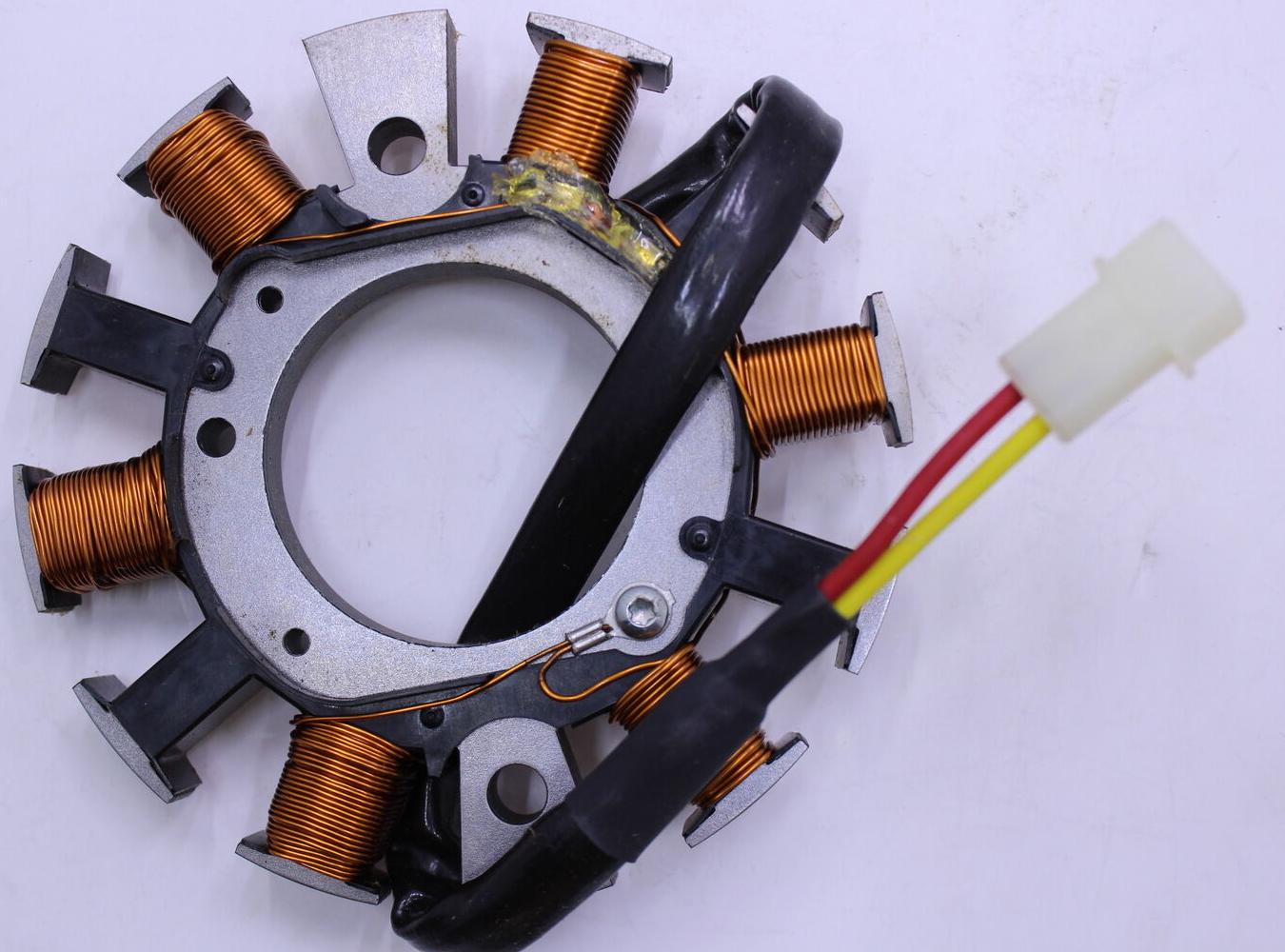
Tecumseh 611104 alternator installed on a 1980s HS50 block.
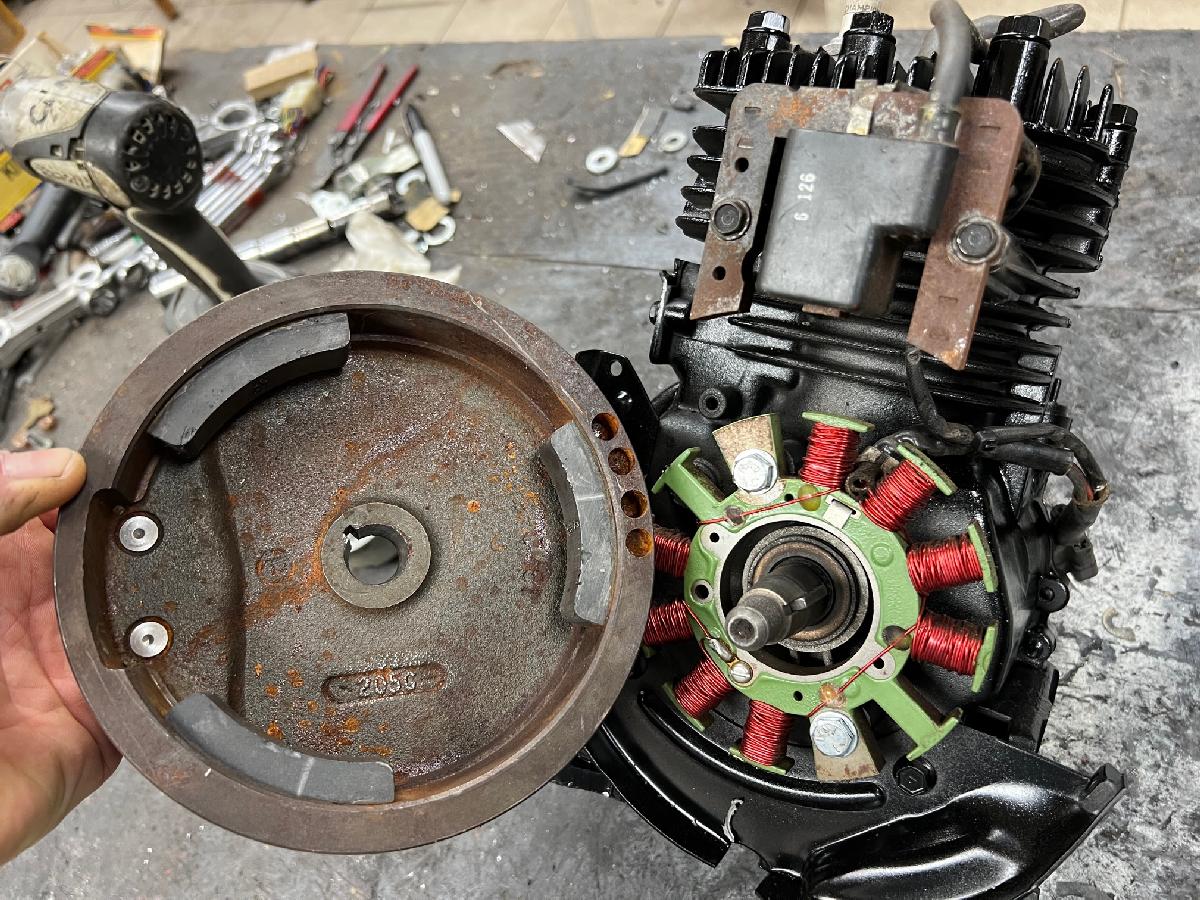
-
There is also the Tecumseh #611111 alternator (CDI ignition engines only), which is an abbreviated
version of the 611104 version. It's about $50 and provides 18 watts of
power. But you will still need to install three large magnets inside
your flywheel. In this case I think the exterior 350ma Tecumseh #34960 is a better choice.
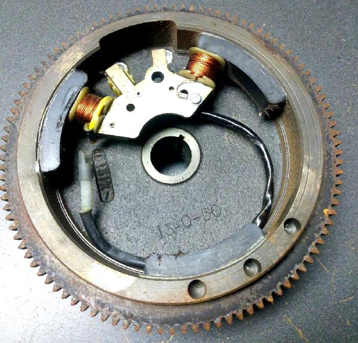
12. Piston Rings and Valves (Honing/Boring).
-
Sometimes you will need to re-ring a motor. This is especially
the case if you're working on a vintage 1970s motor that is
original to your vintage 1970s minibike. That is, a high use motor.
If your HS40 or HS50 motor needs new rings, this section should help with that installation. So how do you know you need new rings? With the spark plug installed, how does it "pull" (with the pull starter)? Do you feel compression? You can use a compression check gauge too. But if the motor has a compression release (some do), this test won't work. Most HS40 and HS50 motors have a BCR (bump compression release). But you can still get some idea on compression by just pulling the starter cord.. The later HSSK50 motors do however have a more severe compression release, which helps with starting the engine. If that's the case, the slow pull start test won't tell you much. If the engine starts and burns oil, chances are good you have a ring problem.
You can also pull the head and just look at the cylinder bore. If it's smooth that's good. If you can see the cross-hatch pattern, that's even better! A lot of snowblower engines will have very limited use. If you see cross hatches on the cylinder bore, you have a very light use engine. That's a great thing! You can also do the piston "wiggle" test, as seen in the video below.
-
If you don't have any history with the motor (that is you've never
seen it run), and you can remove the piston, and remove the top most ring,
you can measure the gap of the top most piston
ring inside the cylinder. This will tell you if there's ring wear,
and if you'll need a new set of rings. Obviously you'll need to remove
the side cover, the cam, and the two screws holding the bottom cap
to the connecting rod (1/4" socket needed.) Then you can push the
piston out of the top of the cylinder.
If for some reason you can't push the piston out of the top of the cylinder, you have a bigger problem. That motor is worn, and you have a ridge ring around the top edge of the cylinder. Hopefully this is not the case, as this would indicate a really worn cylinder. And short of boring it to .020" over, this block will probably be beyond usage.
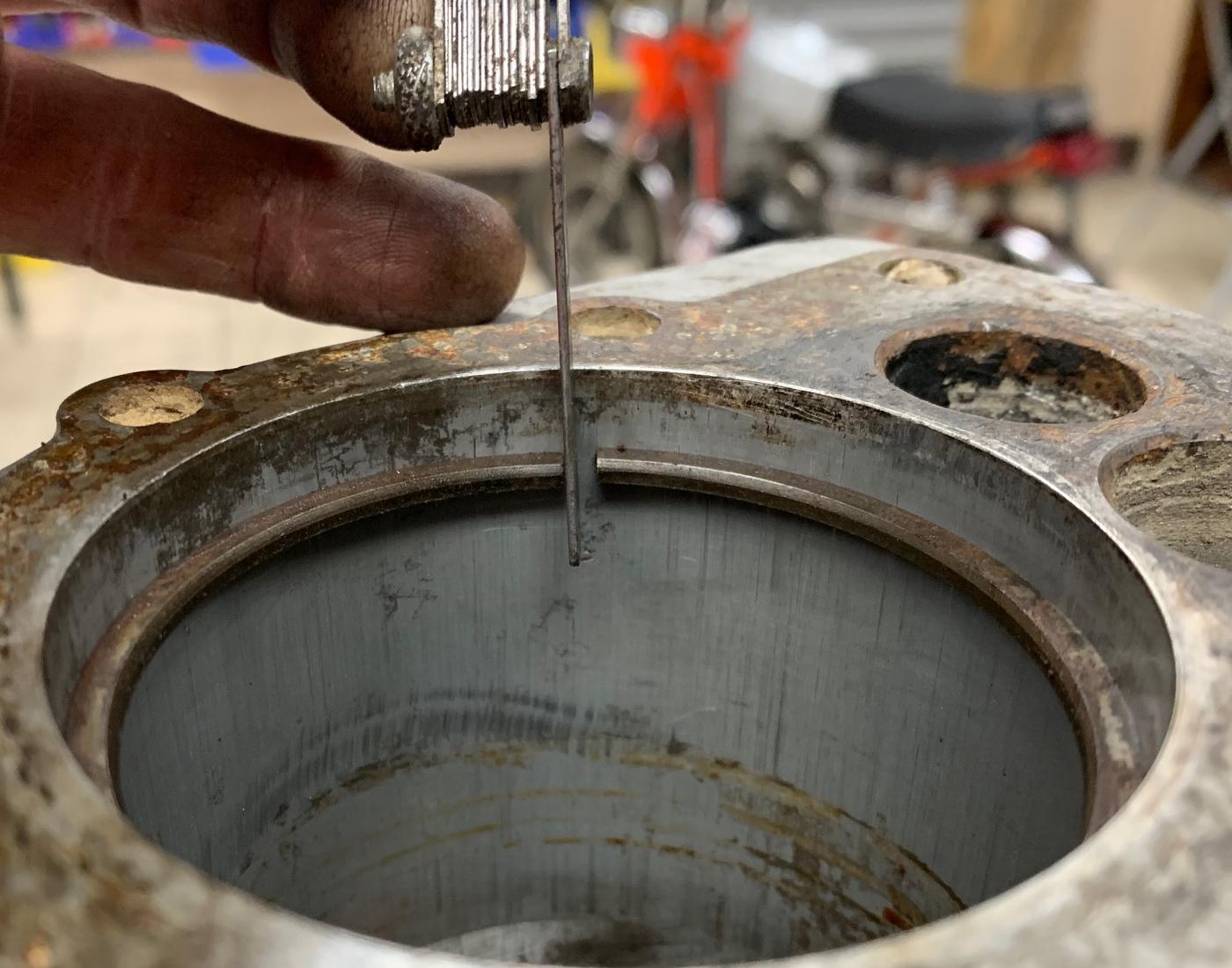
-
When your thick ring Tecumseh engine was new, the ring gap was .007 to .010".
The working specs are .007" to .017" ring gap on thick ring pistons. With a thin ring
piston (after 1992), this working gap is .010" to .020" (with it at .010" when it was new.)
Basically if you get above .020" ring gap (either engine type), it's probably time for
new rings (either engine type). In the picture above, the feeler gauge only goes to .035",
and the ring gap is clearly twice that (if not more.) I would say
this engine needs new rings (or maybe an oversized piston too.)
Because a cylinder wear more at the top and center of the stroke then the bottom, it's better to use a ring gap of .010" on thick ring pistons. Trying to get it to .007" is not a good idea (unless you just had the cylinder re-bored and honed.) Because as the ring goes down the cylinder, it will tighten the gap. If the gap "crashes", you'll be in a world of hurt! And that could happen on a used cylinder. So better to error on the side of caution.
Also when checking ring gap on a used cylinder, you really need to do this at the center of the cylinder bore (I usually go down an inch or so). Why? Because the center of the cylinder wears more than the bottom or top. You could have a .010" ring gap on the top/center of the cylinder, but a .005 ring gap on the bottom. This WILL cause a problem! The motor will run great cold, but as it warms up in a few minutes, it will "soft seize" and stop running. So you must check the ring gap at the bottom of the cylinder too, making sure it's not too tight.
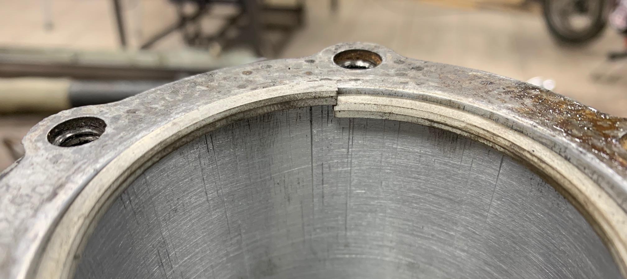
Same cylinder, after honing, but with a new .010-over ring installed. You can see the gap
is almost enough to bring the ring together. But not quite!
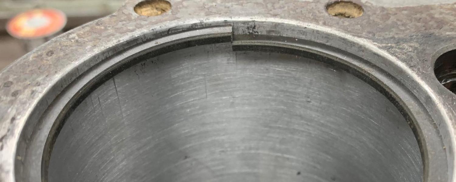
Here's a brand new Tecumseh H35 short block (with thick rings.) This motor has
never been run! Check the ring gap... it measure about .010". That's brand new,
from the factory. This should give you some perspective on ring gap.
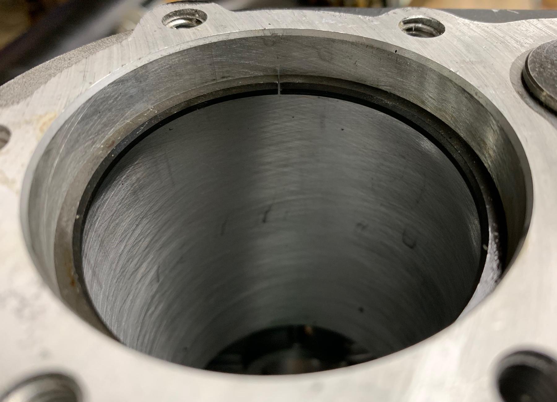
This HS50 motor had a "soft seize". This happened because the new rings were
gapped to .007 at the top of the cylinder, but not checked at the *bottom* of
the cylinder. The ring gap there was about .005... as the engine got warm,
the expansion of the rings tightened the ring gap, and seized the motor. Let
the motor cool, and it would start right back up (for 5 minutes.) Had to
re-hone the cylinder and widen the ring gap, and now the motor works fine.
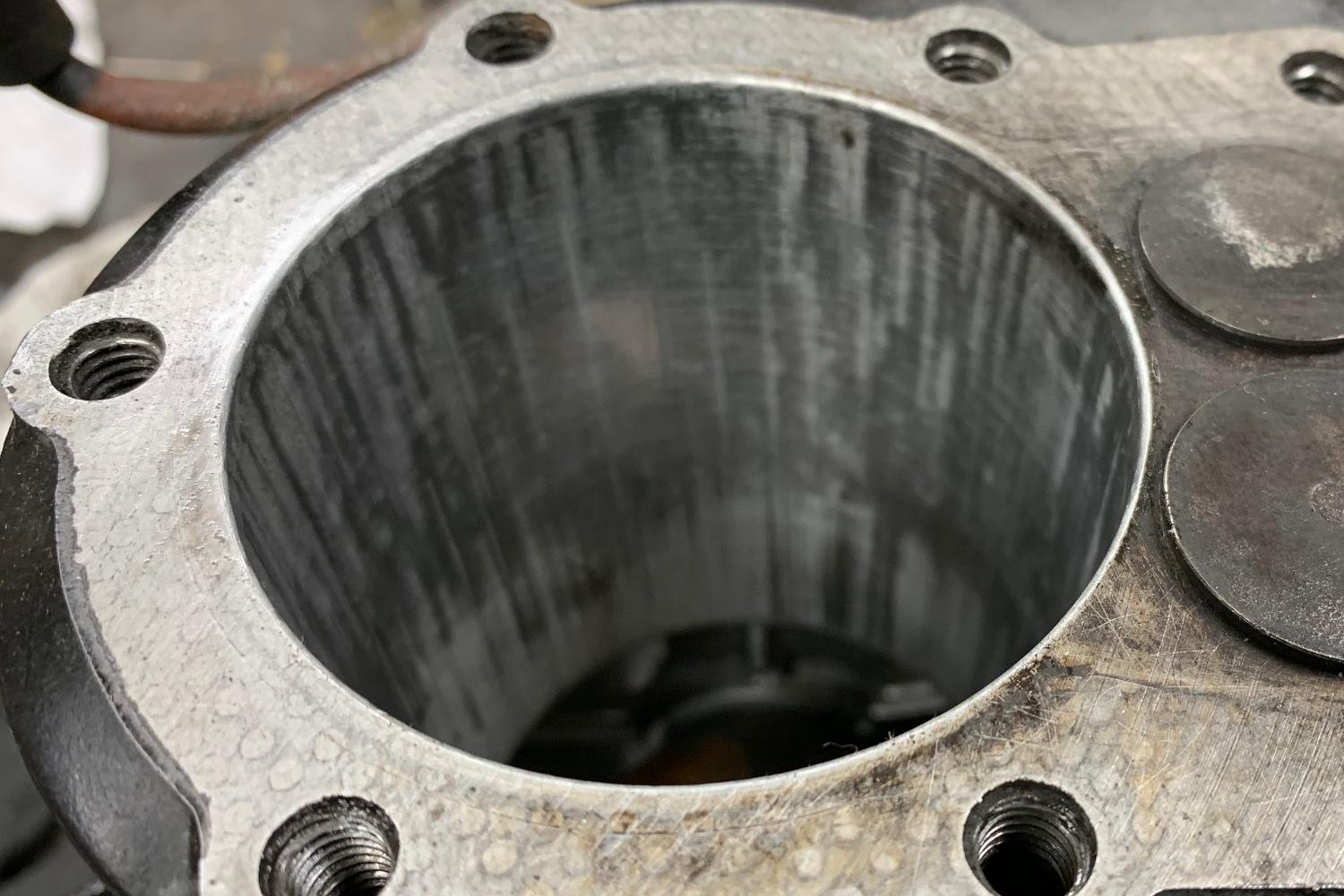
-
Let's say you don't want to bore the cyliner oversized. It's understandable,
you need to have a machine shop do that work (it costs money.) There
is another way to handle this, and that's to use oversized rings, and grind
one end of the ring to get a .010" gap. Though probably not the best
approach, it does solve a problem. It's the cheap way to re-ring a motor
that probably needs to be bored. Use the standard piston, and modified
oversize rings. This does work!
Egg Shaped Cylinder and Boring.
The way these aluminum bores wear is egg shaped. That is, the very top and
bottom of the cylinder stay pretty round. But the middle area wears
unevenly. There's only one way to fix that, and it's boring the cylinder
to oversize. You can not hone an out of round cylinder. You *will*
make it worse, not better, trying to hone it to oversize. For example,
I had a really worn HSSK50 engine (see video above.) I could almost drop
a over-size .010 piston into the cylinder. For fun, i honed the cylinder
to accept the .010 over piston. This took a decently running motor (with
a lot of oil burning, but it ran!) to a completely non-running motor.
If you decide to bore a cylinder, you will need an oversized piston. A machine shop should be able to do this on a Bridgeport Mill for you. Cost is usually about $40 to $50. Make sure you give them the specs and the new piston.
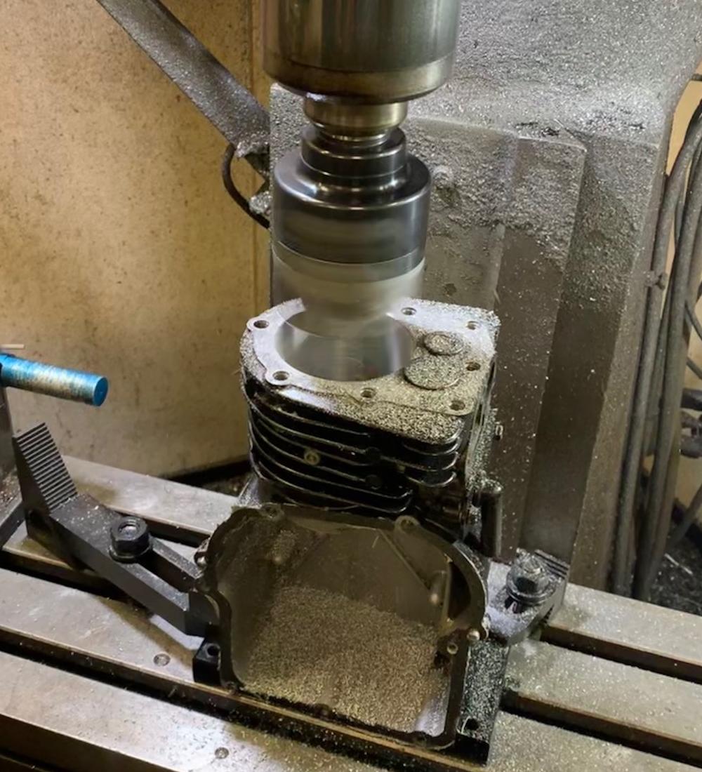
-
If the motor you are boring is a newer HSSK50 or a 1990s HS50 with the thin
ring piston and smaller exhaust valve, there is a way to get an
over-sized piston easily (sometimes over-sized pistons are hard to find.)
When Tecumseh went to the small valve (about 1995) and
thin-ring piston (earlier about 1992) on the HS50/HSSK50, they decreased the bore size from 2.812" to 2.795".
This means you can use an old stock size HS50 thick ring piston #33562, and get almost .020 over
on the newer format HS50/HSSK50 engines. It's cheating, but this does work if you can't
find a proper over-sized piston!
Honing the cylinder.
Before you install new rings (or any sort), you should hone the
cylinder. It wants a cross-hatch pattern for the new rings to seat correctly.
It will also remove light wear or scratches in the cylinder. Honing is
not boring though! Meaning that honing will remove .0005 to .0020" of material (at most).
It's not like boring where lots of material (.010 or .020") is removed. The purpose
is to get that cross hatch pattern, and possibly clean up some light cylinder wall
scratches. It won't remove serious issues. In fact, if your cylinder is out of round,
honing will make it worse (not better.) But honing does help the new rings seat
better and work better.
Boring will make your cylinder perfectly round again - honing does not do this. As a cylinder wears, it tends to go out-of-round (egg shape). Especially at the middle of the bore, that's where you get the most wear. Only boring can return a cylinder back to perfectly round. Remember, the whole idea behind honing is to remove minor scratches and to get that cross hatch pattern. In fact, after a cylinder is bored, it needs to be honed before installing the new oversized piston.
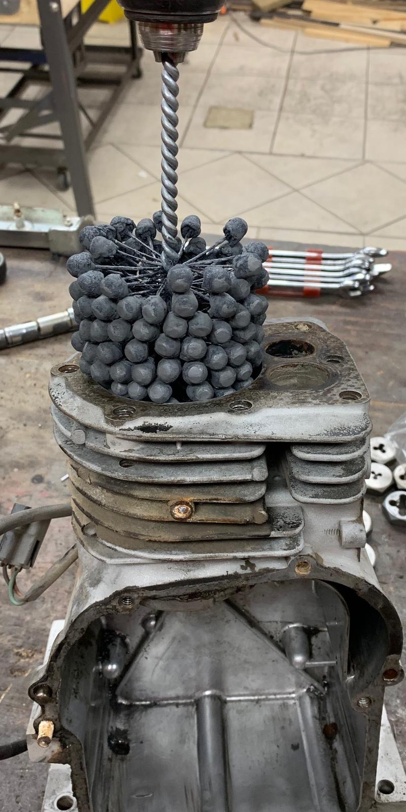
-
There are basically two different styles of hones: the 3-stone type, and the flexhone ball type.
In the picture above, the ball type is used. The flexhone type is a bit easier to use
(as it can be used in a hand drill, where the 3-stone type should be used in a drill press.)
But either style is fine, just get a 320 or 400 grit variety (with 400 grit being ideal).
I have found the ball type hone to be more agressive than the 3-stone type. It's also just
seems to work better and is easier. For this reason I use the flexhone ball type.
Remember hones come in different diameters (and grits) too.
I use a 2 3/4" Flexhone, since it works with an HS40 (2 5/8")
and HS50 (2.812"). Remember you MUST use some sort of oil when honing. Automatic
transmission fluid works really well for this.
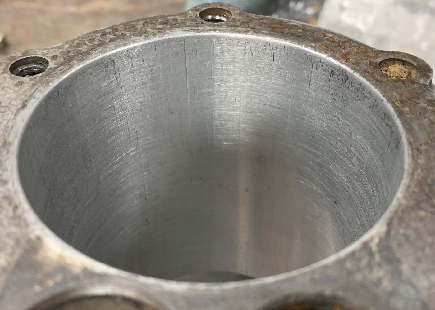
-
So how much honing do you do? Don't spend a lot of time doing this, that's not
the point. When using the bead style hone, I usually move up and down the cylinder
wall for about 10 to 20 seconds. Then wipe down the cylinder and check the cross hatching
and the scratches. Don't go too wild! Remember you're honing, not boring!
After doing the honing, you need to clean the cylinder really well. The aluminum that gets left behind is just like sand paper. It needs to be cleaned. The right way is to put the cylinder in a soapy water bath (kitchen sink). Then wipe the cylinder down with a white cloth. Any gray on the cloth, and you need to keep cleaning that cylinder. No gray on the cloth, and you've got it clean!
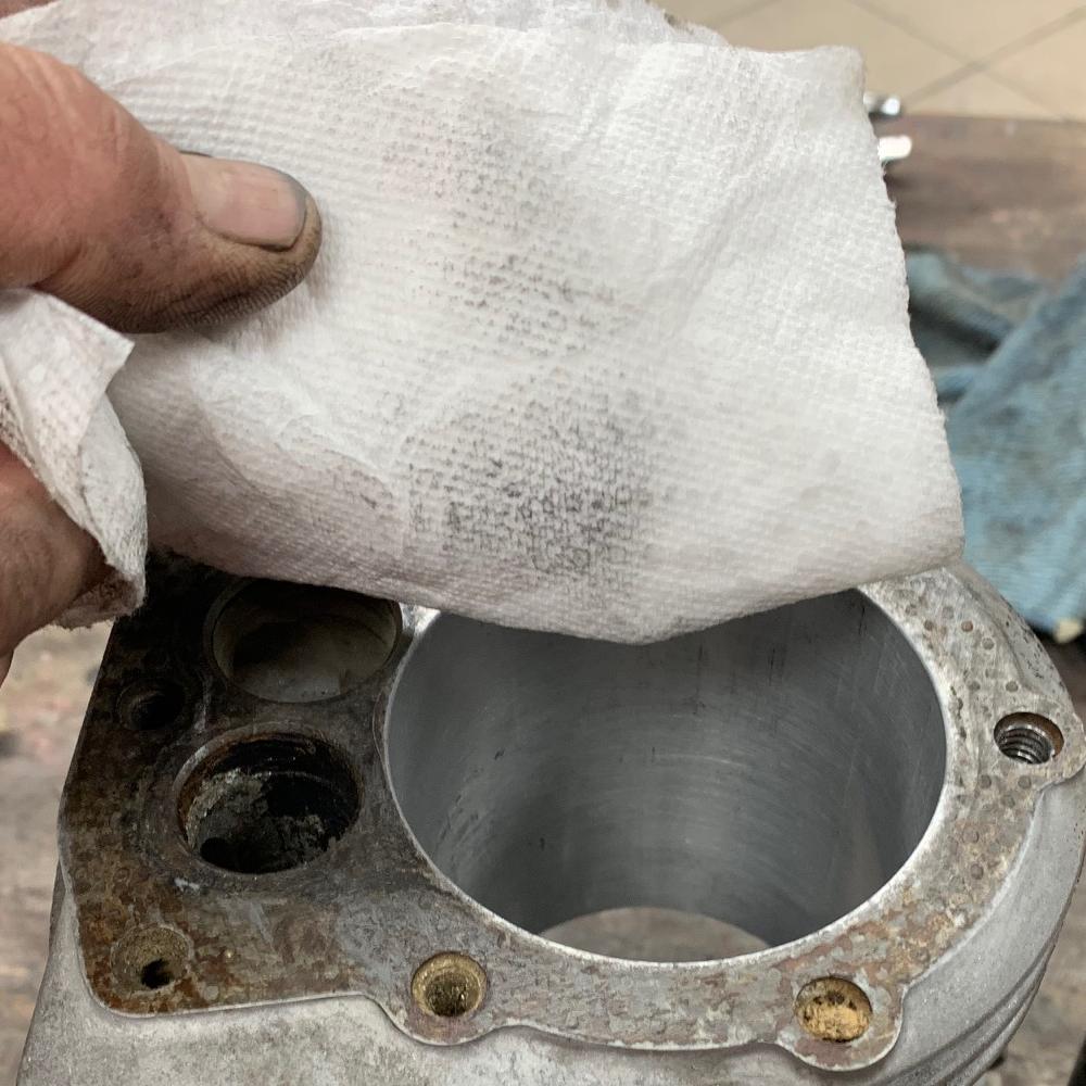
-
Installing the New Rings.
Getting the old rings off the existing piston is easy. Brute force works fine, you're throwing them out anyway. But getting the new ones on is much harder. Because you can easily break a new ring! The best way to do this is using a piston ring expander tool. You can do it without this tool, but it's not recommended.
-
The bottom most
ring is the oil ring. I do that one first. Often it has a spring metal
expander that goes on before the ring. That's easy to put on. But the oil
ring itself I install from the bottom of the piston. Walk it up the
piston skirt slowly, until you hit the bottom most ring gap.
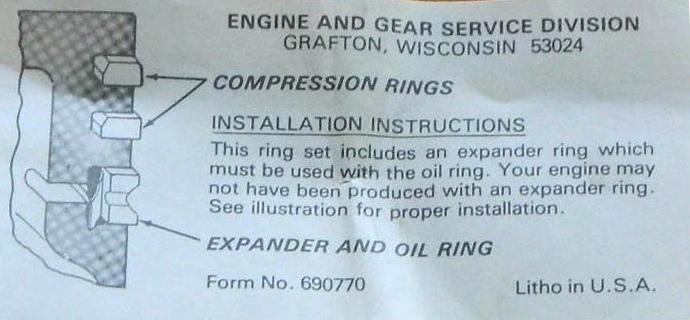
Another ring chart. Style #1 is the most common, but sometimes you'll see
Tecumseh rings made in Style #2, with an added spring steel expander ring behind
the middle and bottom ring.
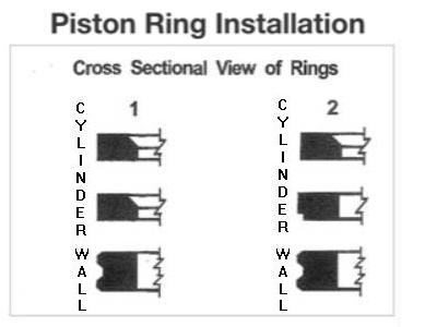
Yet another ring chart. This is basically the same as seen in the chart#2 above.
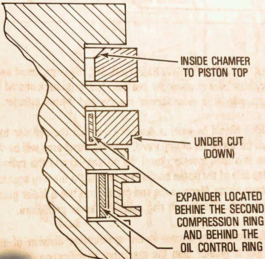
-
The middle ring I put on from the top. Again walk it on slowly. Then do the same
thing with the top most ring. Also
note there is a "top" and "bottom" to the new rings. Usually there's a form #690770
in the ring box that explains position (it can vary from set to set.) For old
school thick rings, the picture above shows the position of the angles on the top and middle rings.
Ring Gap Positions.
The position of the ring gap is really important. Basically you want the ring gaps
to be spread 120 degrees away from each other. But there are some other things to
consider. First never put a ring gap right next to the values. Also never put a
ring gap over the wrist pin. So that kinds of leaves you with a certain position
that works!
Also many pistons have an arrow on the top of the piston. This should be oriented towards the values.
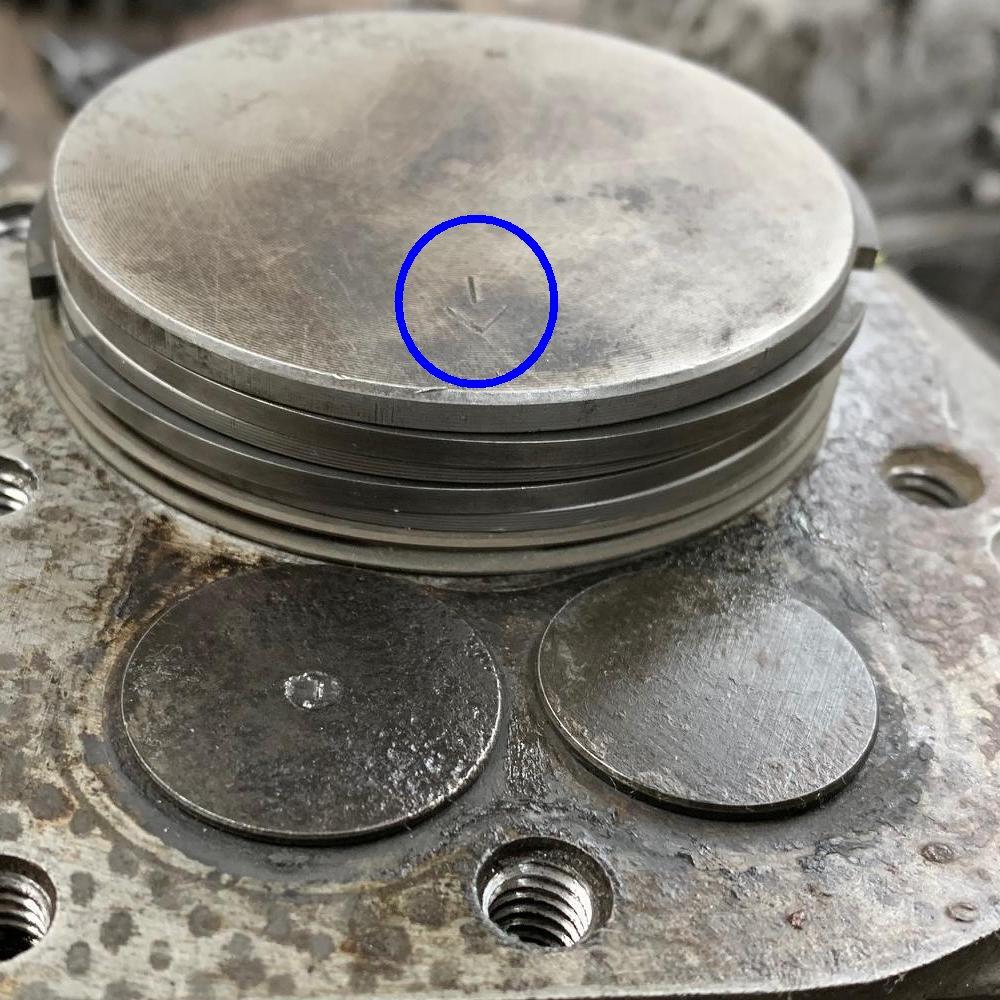
Here's where the ring gaps should go on these engines
(positioning the ring gaps about 120 degrees apart.) Don't position the gaps right next to the values,
and don't position the gaps right over the wrist pin.
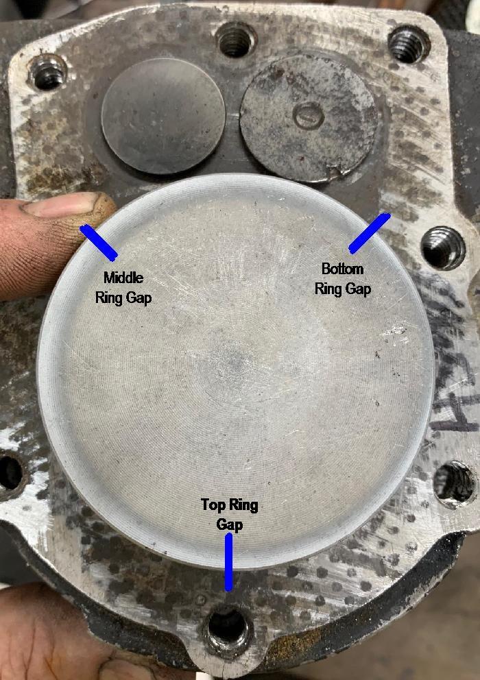
-
Now to slide the piston and new rings into the cylinder, you will
need a ring compressor. You can probably do it without it, but it's
not worth the risk (of breaking a ring.) Just buy one. Put oil on
the cylinder wall, and on the wall of the ring compressor. Tighten
the ring compressor as tight as you can, and put the piston in the
cylinder (from the top.) Then using the wood handle of a hammer, you
can knock the piston into the cylinder.
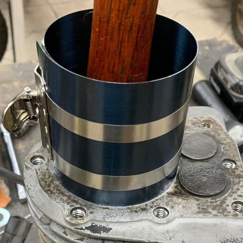
-
Rod/Piston Positioning.
Often this is a bit confusing. Tecumseh at some point put an arrow on the top of the piston, which should point towards the valves. That make this easy. But if that's not there, it's not hard to install the piston "backwards" in the cylinder. Also it's not difficult to get the rod cap installed backwards too! The picture below should help this. Note the orientation of the rod and the oil dipper and the rod cap.
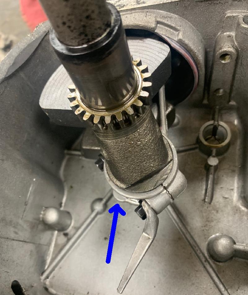
Rod cap casting mark.
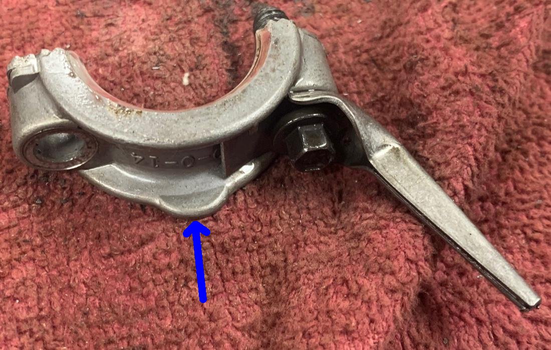
-
Also when putting the case back together, always use a
new gasket. I like to clean both case surfaces with a
solvent, and then lightly coat with Permatex gray silicon
gasket sealer. No one likes a leaky engine! So doing this
keeps it oil tight. Also after applying the gray silicon
to both case halves, let it dry for about an hour. Then
put it together. This helps a lot with the seal.
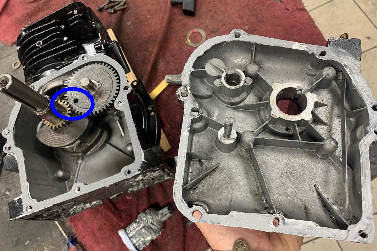
-
Also of course make sure you line up the dot on the
crankshaft gear with the big hole (and a line) on the
camshaft. If you get this gear alignment wrong, the engine won't run!
13. Cams, Valve Lapping, Valve Springs.
-
The cam used on HS40/HS50/HSSK50 motors are the same from 1972
up till the end. It's a bump compression release (BCR) cam, part #33158.
Early HS40 motors (about 1968 till 1971) used a mechanical compression
release (MCR) cam, part #32701 (note this cam uses a different lifter.)
But other than that, all HS40 and HS50 and HSSK50 cams are the same from 1972 to 2008.
They are not high performance. You can however get high performance cams.
But they mostly effect and allow higher RPMs. If you go this route, you
will need an ARC billet #6282 connecting rod, because all high performance
cams add RPMs! Just keep that in mind. If you don't use a better
connecting rod, you will "throw the rod" and probably ruin your engine.
- Stock Tecumseh HS40/HS50 cam lobe lift: 0.975"
- Dynocam 245 HS40/HS50 cam lobe lift: 1.050". Kicks in at 3000 rpm. Lobe size is 1.045"
- Dynocam 255 HS40/HS50 cam lobe lift: 1.060". Kicks in at 3500 rpm. Lobe size is 1.055"
- Dynocam 356 HS40/HS50 cam lobe lift: 1.150". Kicks in at 5000 rpm.
Dynocams.com in Delco, North Carolina (910-655-9035) does offer a "245", "255", and a "356" cam for the Tecumseh motors. They are specified for the HSSK50 motors, but will work in an HS40 or HS50 engine. In order to get these cams you have to send them a "core" and some money, and they will grind the cam desired. Here's the specs on the cams:
The Dynocam 245 is a nice cam. It is almost identical to 94-SS Briggs & Stratton flathead grind which has been the most popular DynoCam flathead cam for many years. The 245 doesn't seem really a lot different than the stock cam, except it allows the motor to accelerate noticeably faster. Also it will allow for higher RPMs (though probably not much more than 5000 RPMs, which is a bit more than the stock Tecumseh 3600 RPMs). You can use the existing valve springs and retainers too with this cam (they suggest not using stronger springs, because this cam is not welded or heat treated.) Pull starting does not seem any more difficult with this cam. It's a nice all around cam that gives a bit more performance. The 245 cam was designed to be "dropped in" to an otherwise stock motor and give added performance.
The Dynocam 255 is more aggressive than the 245. The 255 is very close to the Predator/Honda clone "mod2" cam with a little more lift. It's probably the "sweet spot" in the Dynocam line. The Dynocam 255 is designed for a modified motor; that is an engine with open exhaust and bigger carb, which allows the 255 to give great performance. Again you can use the stock springs, though a slightly more aggressive spring would be better. Because this cam will allow for higher RPMs (probably into the 6000+ range.)
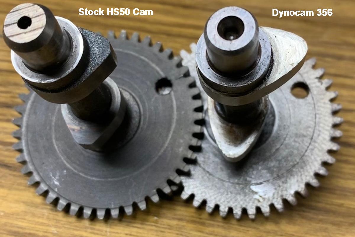
-
The Dynocam 356 is a beast. It has a lot higher lobes, and will probably
make your low end suffer. But you can turn up to 8000+ RPM with
this cam! It is a welded and heat treated cam, meaning that you
can (and should) use stiffer valve springs (or the valves will "float"
at higher RPM.) You should also have a ball bearing crank side cover too.
I don't recommend this cam unless you are a racer.
(And if you're a racer, you're probably not reading this document
anyway.) Also the valve lift is so high this cam will not
work with a stock head (the valves would hit the head.)
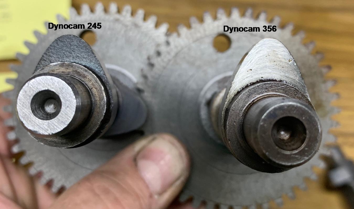
-
When using a Dynocam 245 or 255, carb jetting should be maintained.
That is, a higher performance cam does not generally change carb jetting.
Just keep that in mind.
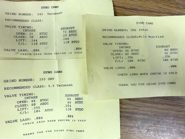
-
There's another company that does cam grinding for small motors called
Small Engine Cams (Gardena CA 310-769-6880).
You can contact them for a higher performance cam too.
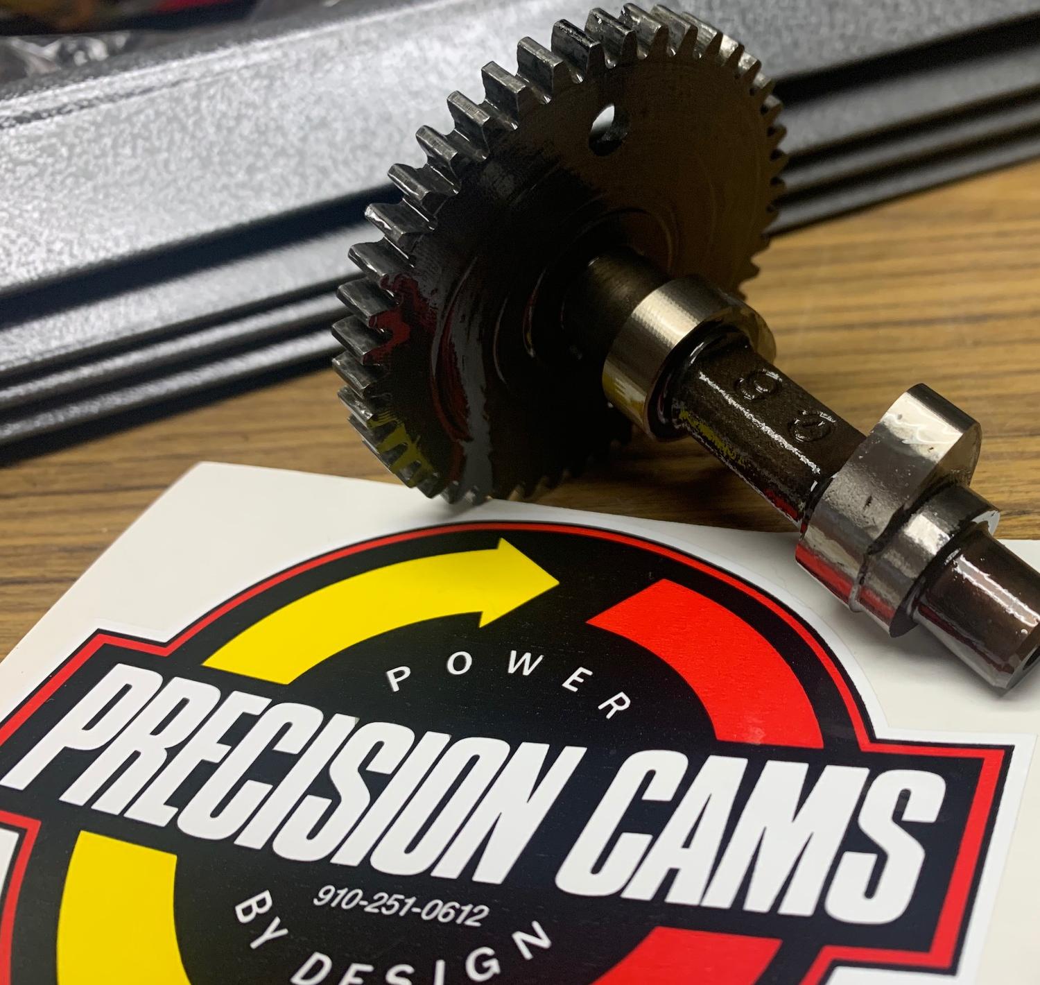
-
Yet another cam company is Precision Cam.
They are located in Wilmington NC (910-251-0612) and are an "old school" type shop (meaning they
really don't answer email, they prefer phone calls, and their website is not updated.) If you send them
stock Tecumseh cams they too will grind them. Their popular Tecumseh grind is known
as the 30/30 grind. This is essentially a Dynocam 245.
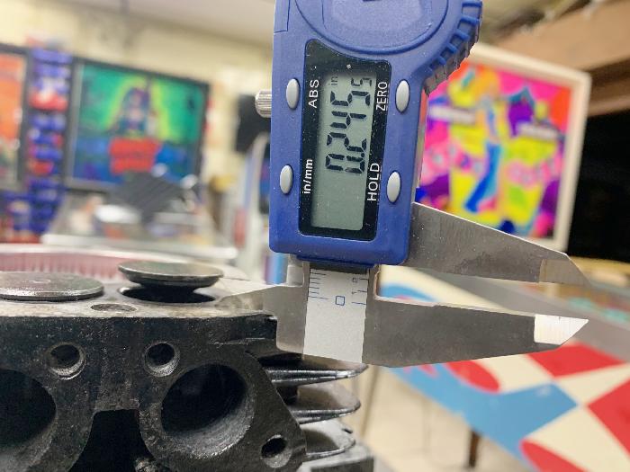
Here's the exhaust valve on an LH195 engine with a stock cam. The lift appears to be about .280".
This is more lift than a stock HS40/HS50 cam, and maybe how Tecumseh claims it's 5.5hp engine?
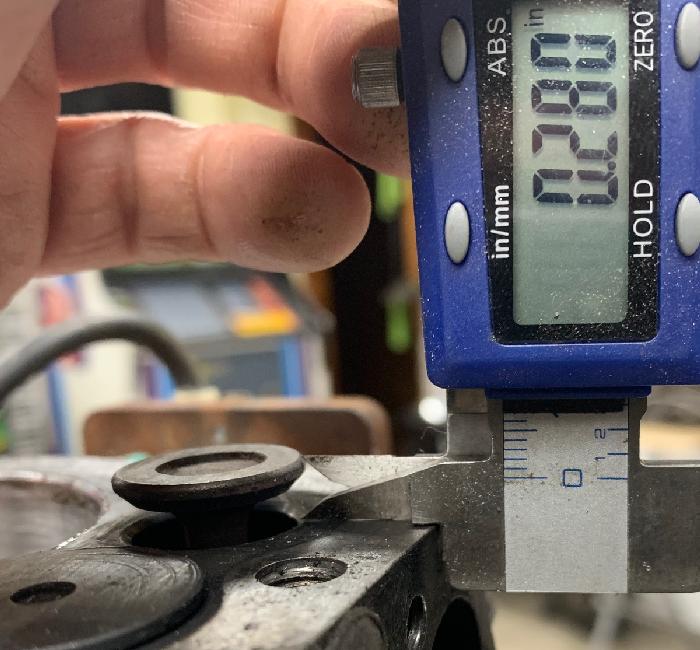
Here's the exhaust valve on an HS40 engine with a Dynocam 245 or Precision 30/30 cam.
The lift appears to be about .330". This is considerably more lift than a stock HS40/HS50 cam.
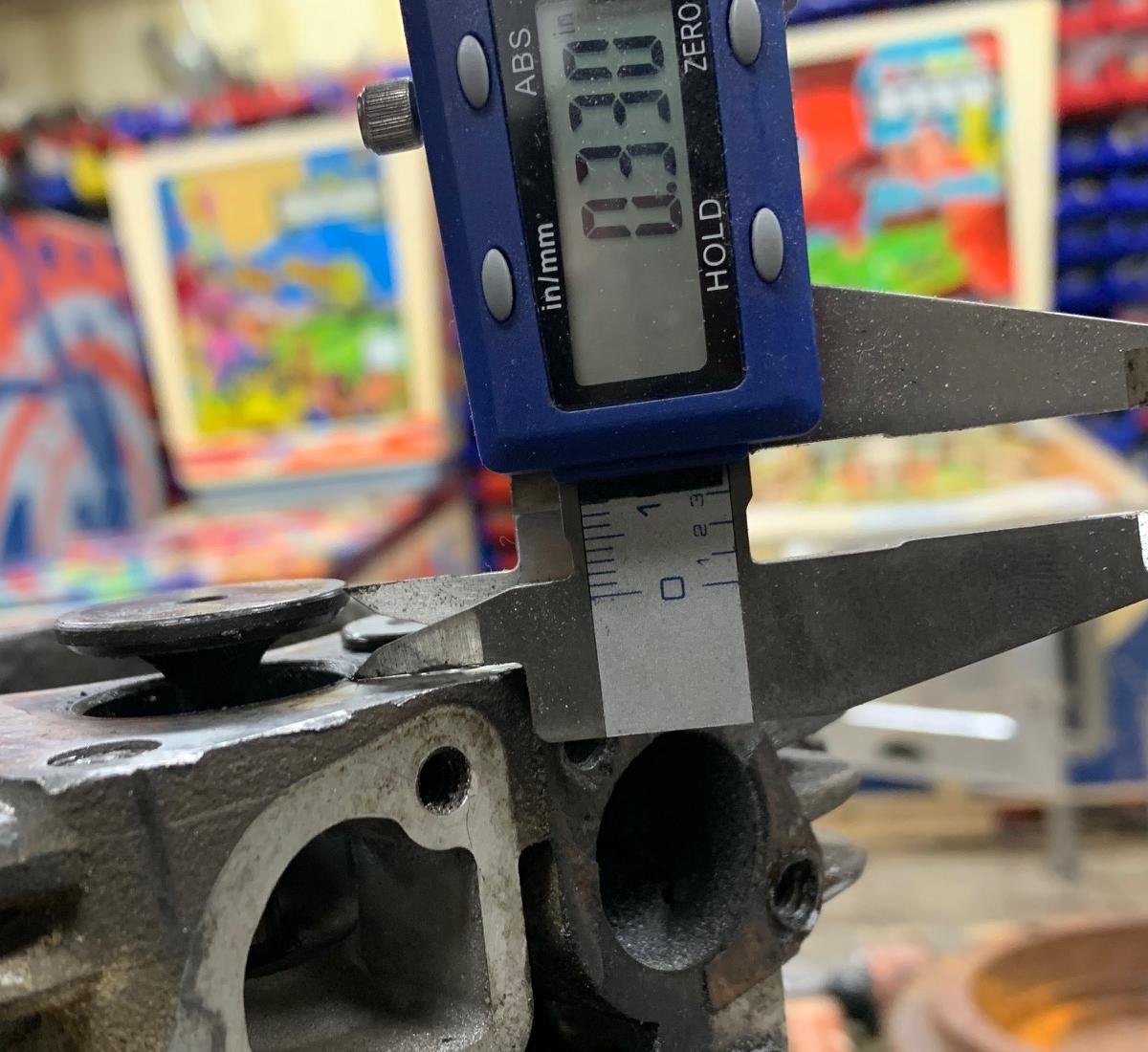
This picture show a cutaway head on an HSSK50 engine with a dynocam245 installed.
Notice the exhaust valve is hitting the top of the head! (This picture does not
have the head gasket installed, which is about .065" thick.) What this means is
there's not a lot more lift available on a stock head HS engine with a modificed
cam installed.
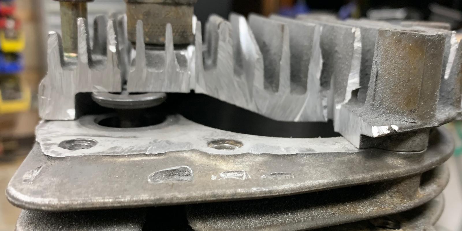
-
All that aside, a stock cam should be checked.
Mostly the issues I have seen are on the newer HS40/HS50/HSSK50 engines.
Tecumseh added a slight "bump" to the exhaust lobe on these cams, known
as the "bump compression release" (BCR). The bump is nearly oppose of the
exhaust cam lobe. This bump comes into effect on the compression stroke, as a compression release,
to make starting easier. Check your engine
for this! It's easy to check. Just remove the head, and turn over the engine
by hand. Look at the compression stroke, from the bottom of the stroke to about
1/2 the way up. If you see the exhaust valve "bump" up
just a bit (probably about .010"), you have one of these cams.
My suggestion is to modify this cam to remove the "bump". Otherwise your
compression will be reduced quite a bit, compared to a non-release engine. It's actually pretty
easy to do. With the cam removed, you can feel the "bump" (on the side of the lobe). I use a belt
sander and gently grind the bump off the side of the exhaust lobe on these cams.
Then re-install and check the exhaust valve (to make sure there's no compression bump
on the exhaust valve.)
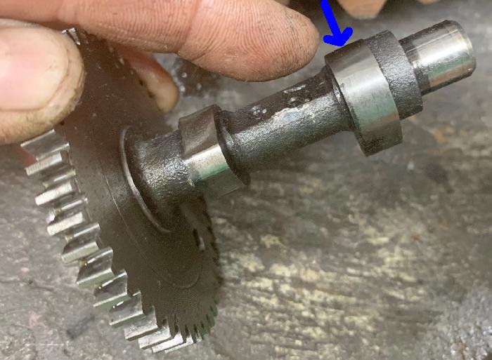
Here's a stock cam with the BCR compression release on the exhaust lobe (blue circle).
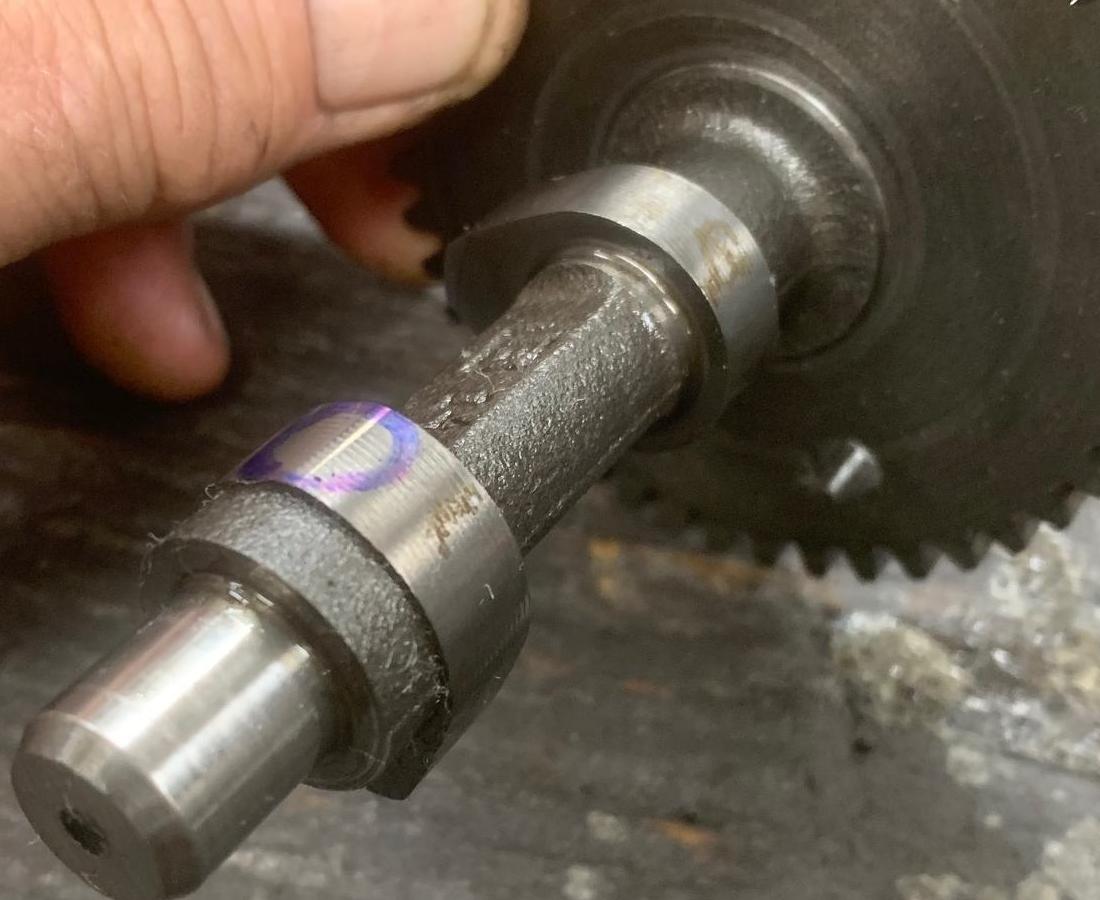
-
So why did Tecumseh add this compression killer? Well it makes the motors start a lot
easier (there's nearly no compression "kick" when pull starting.) But
unfortunately, there's no way to turn off this compression release.
Some early HS40 cams had a mechanical release. This is nice, because
as the engine starts, the release disables, so you get full compression
as soon as the motor starts. But with this new style BCR cam, the compression
release is always present. It tones down the performance of these engines.
It's a fine thing for a snowblower, but it sucks for a minibike!
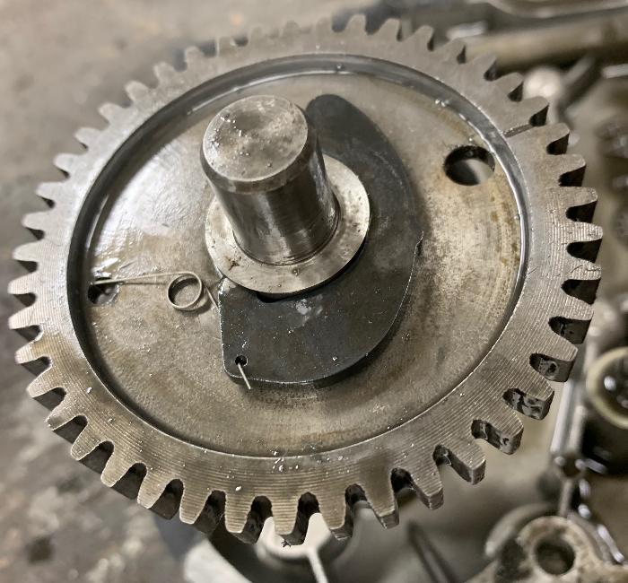
Cam from an early HS40 engines (about 1968-1971) with a mechanical compression release (MCR).
Note the one lifter for the intake is shorter than the exhaust lifter. That's
because the intake cam lobe is huge, to accommodate the mechanical compression
release.

Some LH195 engines have a plastic cam (left)! Obviously you don't want that.
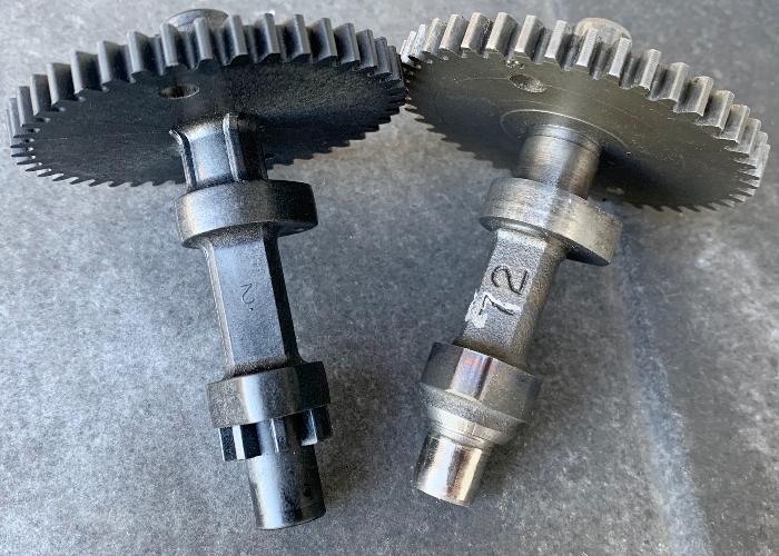
- Comp Cams GP971 spring (Briggs Animal). Rated at 17 pounds.
- Dynocam DCS-AN spring (Briggs Animal). Rated at 18 pounds. For use with their Briggs AN001 cam.
- Dynocam DCS1360 spring (Briggs flathead springs). Rated at 16 pounds.
- Dynocam DCS1420 spring (Briggs flathead springs). Rated at 18 pounds.
- length uncompressed: 1.100"
- length compressed (using a vice): .480"
- outside diameter: .820"
- inside diameter: .625"
- wire thickness: .085"
- length uncompressed .910"
- length compressed (using a vice): .465"
- outside diameter: .835"
- inside diameter: .620"
- wire thickness: .100"
- length uncompressed 1.475"
- outside diameter: .810"
- inside diameter: .625"
- wire thickness: .085"
On early HS40 engines there is sometimes a mechanical compression release. In this case the lifter used for the intake valve is shorter than the exhaust lifter. The shorter lifter is 1.318" in length, compared to 1.478" for the exhaust lifter. The longer 1.478" lifter is the standard lifter used on non-MCR lift cams on HS40 and HS50 engines. They use a shorter lifter because the intake lobe on the MCR cam is huge, to accommodate the MCR. If you install a Dynocam or even a regular HS40/HS50 cam, you will have to replace the short lifter with the 'normal' length (1.478") lifter. Note on the LH195 engine the valve lifters are a different length at 1.445" tall.
Valve Springs.
If you use a bigger cam, stronger valve springs would be helpful. Above
say 5000 rpm, the stock springs will 'float the valves', because they
can't kick the valves back quick enough at the higher rpms. Most people
use a stronger valve spring to solve this problem. The downside of this
is it puts more wear on the cam lobes. Basically you don't want to go nuts
with too strong of springs!
If you're using a Dynocam 245 most racers recommend an 18 pound spring. This will prevent valve float at 5000+ rpm. Dynocam doesn't want you to go nuts either with spring tension, as their 245 cam (they say) doesn't have the wear properties to handle big springs.
Poking around the interweb, I've found that most kart racers use Briggs cam springs on the Tecumseh. That's because no one makes a replacement spring specifically for the Tecumseh flat heads.
To solve the potential floating valve issue when using a bigger cam, the following is what seems to be available. These could potentially work in a Tecumseh HS series engines:
Here's the Tecumseh HS40/HS50 valve springs specs we need to emulate:
Here are the 18 pound Brigg Animal springs specs (DCS-AN or GP917), which is an OHV engine, and have the following specs:
And lastly here are the Brigg flathead 18 pound springs specs (DCS1420). These are definitely too long. Here's the specs:
I'm playing around with the springs. An answer may be to take the 18 pound Briggs flathead spring and cut it to the proper length. Not ideal, but it may be the simpliest answer.
Comparison of springs. The left most is a Briggs 18 pound flat head spring. Tecumseh stock HS spring
is next to it. The two springs on the right are the Briggs Animal 18 pound spring, with and without the
aluminum DCSH102 retainer.
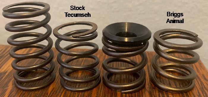
- Dynocam DCSH102 aluminum lower retainers (one for each valve).
- Dynocam DCSH103 split lock spring keepers (two for each valve).
The above Briggs Animal springs appear to be about .200" shorter in length than the stock Tecumseh springs. But if you convert to Dynocam aluminum billet retainers (which are thicker), the spring length is somewhat made up (the retainer is about .100" thick). Here's the parts that are often used:
With the above retainers and keepers you still need to use the stock Tecumseh hs50 upper spring retainers #27882. The Dynocam DCSH102 lower retainer and DCSH103 keepers will need some machining to work on the Tecumseh valves. That's because those aluminum lower retainers are actually for dual springs. The inner riser needs to be machined off the retainer, so the spring sits flush to the outer riser (lip).
Left: Animal 18 pound spring DCS-AN or GP917 with the aluminum DCSH102 lower retainer. The step
(blue arrow) needs to be removed on a lathe.
Right: Animal 18 pound spring with the aluminum DCSH102 lower retainer modified on a lathe to remove
the step. The DCSH103 split retainers are there too. Also shown is an original Tecumseh stamped steel lower retainer.
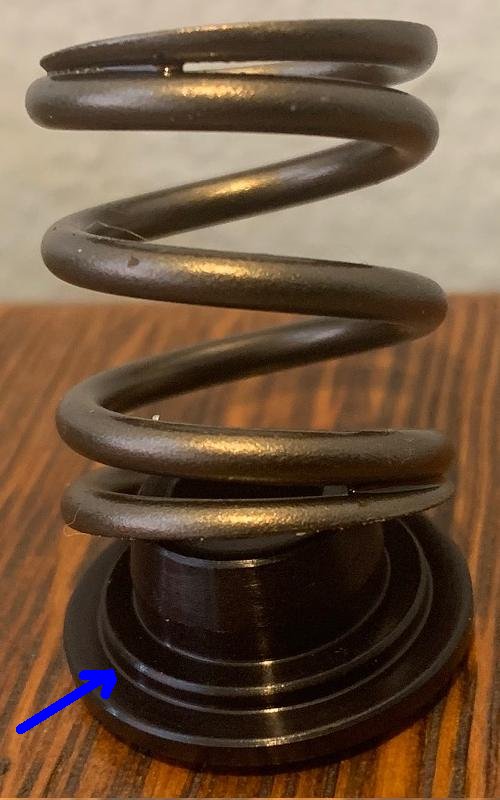
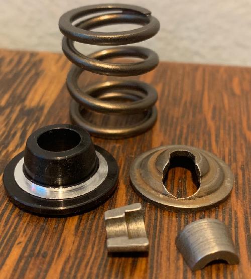
Here's the modified DCSH102 lower retainer and the split keepers DCSH103 installed on a Tecumseh valve.
Also shown is the original stamped steel lower Tecumseh spring retainer.
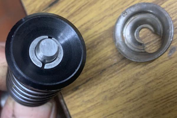
Here's a stock Tecumseh valve spring (left) and a Briggs flathead 18 pound spring, which was
cut to the same length as the Tecumseh spring. This setup would give a stiffer spring and could
be used with stock Tecumseh lower and upper retainers.
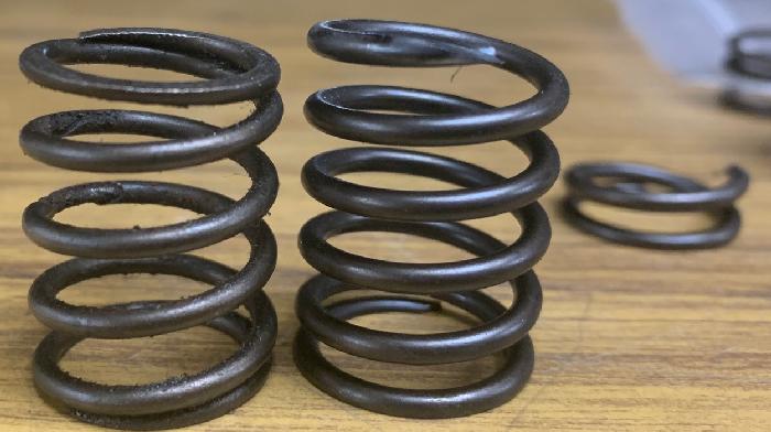
-
Lapping the Valves.
If you already have the motor apart, I would highly suggest lapping the valves. Basically this requires some valve lapping compound (cheap), and a wood lapping stick. This mates the valves to the valve seat, and will help increase compression. It only take a small bit of time to do this, and costs nearly nothing. It's a good idea to do.
In order to lap the valves you'll need some valve lapping compound and a lapping tool (basically a wood rod with a suction cup.) I used the Permatex 80036 valve grinding compound. You can buy a kit with the compound and tool for about $10 on ebay.
To do this you'll need to remove the valves. This is pretty easy. You can do this with the side cover (and all the parts like the cam/lifters) installed, or with the side cover off. Frankly it's easier to lap the valves with the side cover off and the valve lifters removed. But frankly, it's only a bit more difficult with the side cover and all parts installed. An advantage to doing this with the side cover installed is you can measure the valve lash. With the side cover off, you can't get an accurate valve lash measurement. For this reason usually lap the valves with the engine fully assembled, only removing the head and the valve breather.
Remove the side valve breather assembly #31337 and it's gasket #31619. Two 5/16" machine screws hold it in place. With it removed, the valve springs and retainer clips are visible. It's easiest to do this with the valve lifters removed (which means the side sump cover is removed, and the cam removed.) But it's not totally necessary to have the lifters removed (just easier.) The spring retainer clips are notched. Just move the retainers off their center, and this releases the valve spring. I use a flat head screw driver to do this, lifting the retainer as you push it sideways a bit. This should release the retainer - it's really pretty easy. Then the valve can be lifted out.
With the valves removed, you can clean up the valves and the ports. Using a Dremel wire brush works great for this. You can also put the valves themselves on the wire wheel and get all the carbon and other junk off.
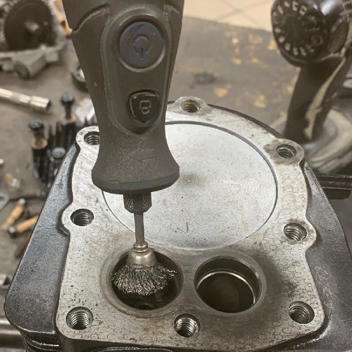
Cleaning up the valves on a wire wheel.
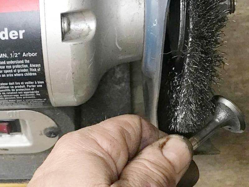
-
Next thing is optional. If the valve seat are still crusty, you can use
some emery cloth and clean them further. Just punch the valve through the
emery cloth and use the valve to help clean the seat.
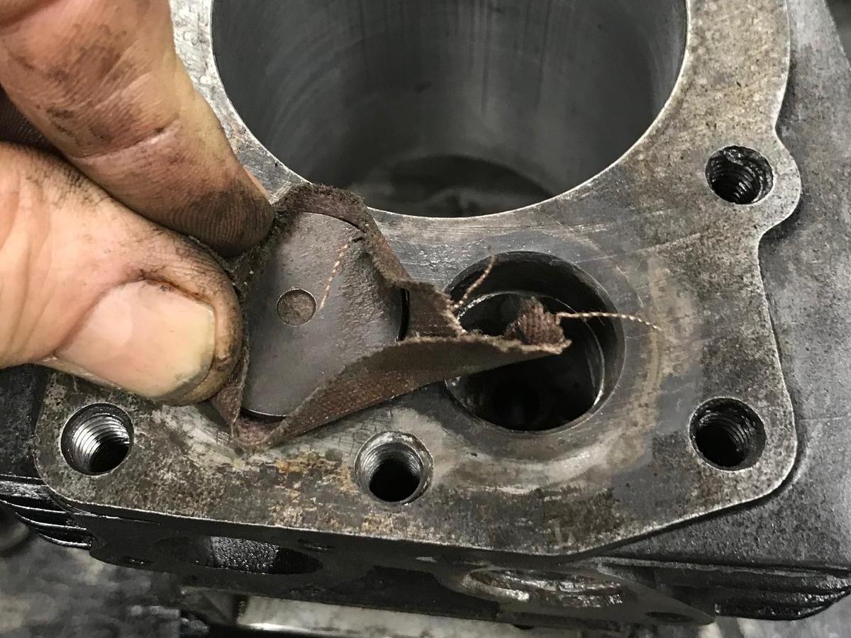
-
Now comes time to lap the valves. Put a thin layer of valve lapping
compound on the valve seat. Then insert the valve, and attach the
suction cup tool to the top of the valve. Then you can twist the tool
between your hands to lap the valve. Pull up the valve after a few seconds,
and repeat. This should give a nice lap of the valve to their seat.
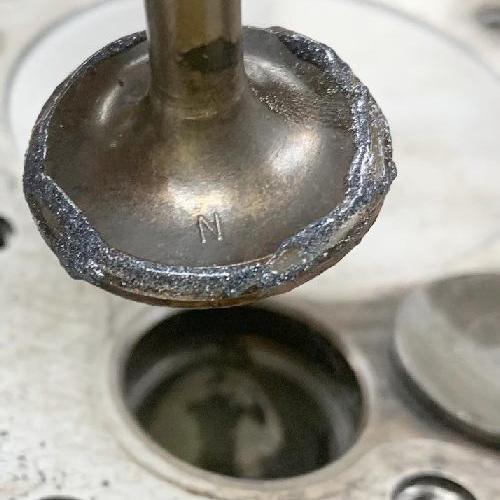
Lapping the valve to the seat using the lapping suction tool.
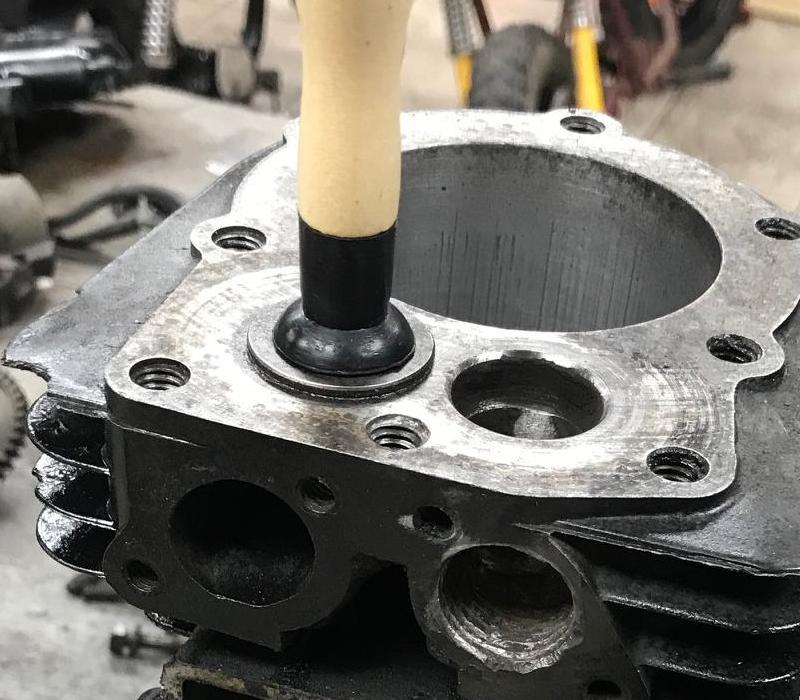
How the valve and the seat should look after a sucessful lapping.
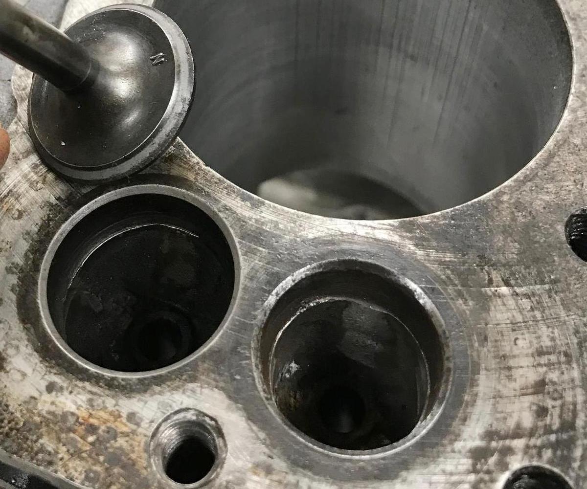
-
With the valves lapped, now comes the time to re-install them
with the valve springs. Again this is easier with the valve
lifters removed. If you don't have a spring compression tool,
use nylon ties to compress the valve springs.
Once this is done, it's easy to insert the top cap, the spring,
and the lower retainer onto the valve. Once in position, just
cut the nylon ties and pull the nylon ties out with pliers.
Alternatively, Briggs and Stratton sells a nice valve spring
compression tool #19063 that works really well.
Use nylon ties to compress the valve springs for easy installation.
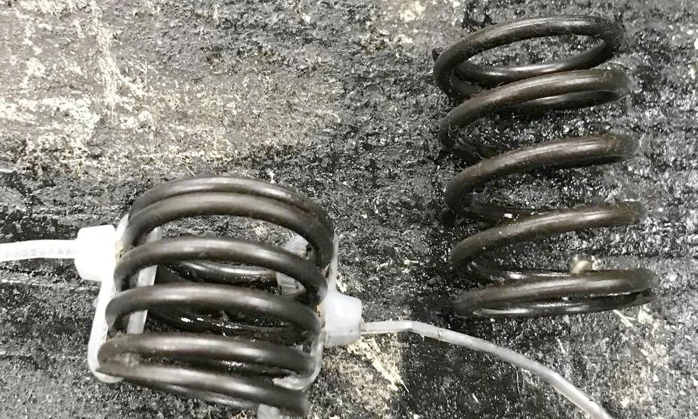
The Briggs and Stratton valve compression tool #19063, if you want to be fancy.
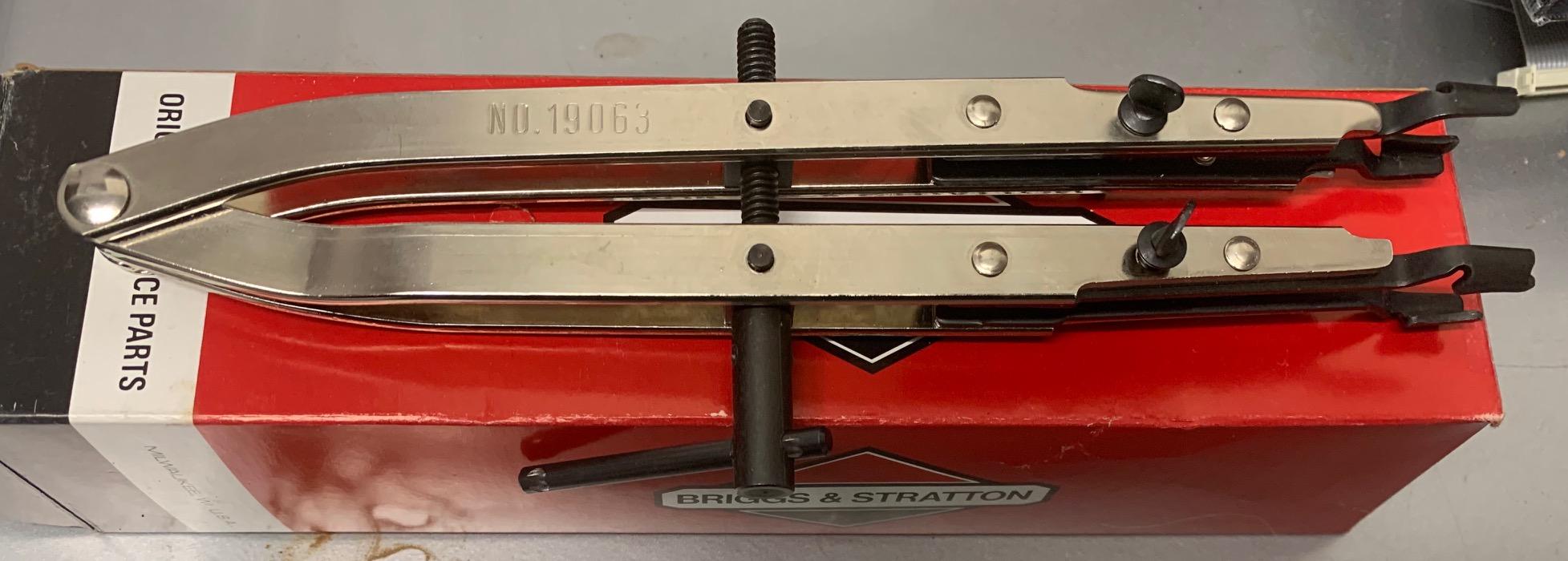
The valve parts. Note on some motors (HS50), the exhaust top spring retainer is
different than the intake spring top retainer. This is important! Don't mix
them up. The exhaust spring top retainer has a bigger hole, because the
exhaust valve seat extends into the valve spring area (see next picture.)
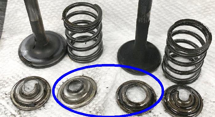
Exhaust seat on some motors (HS50) extends downward. That's why the top spring
retainer has a bigger hole to accommodate the extended exhaust seat on HS50 engines.
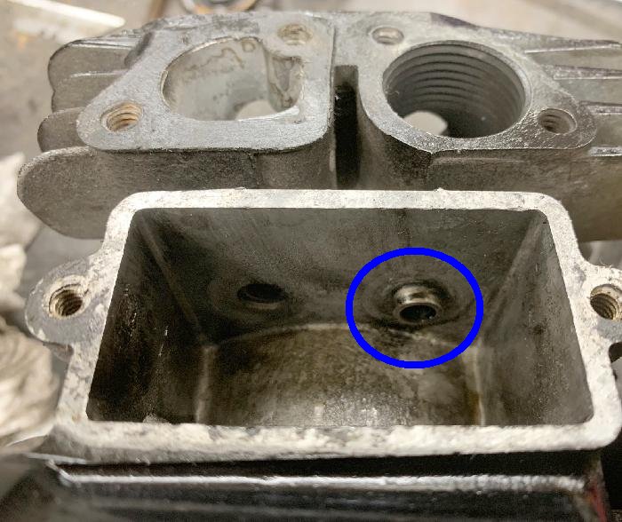
After the valve spring and top and bottom retainers are installed, cut
the nylon ties and pull them out with pliers. (This is an HS40 engine,
and notice the exhaust seat does not extend into the spring area.)
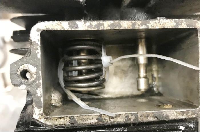
-
With the valve springs and retainers installed, the lifters and cam can
be re-installed (assuming you removed them to lap the valves.)
I would like to add that on some HS50 and HSSK50 and LH195 engines (basically 1990s and newer Tecumseh flathead 5hp motors), there is *no* top spring retainer! For some reason they removed these from these designs. I don't really like this, as the spring could wear across the top of the valve area (into the aluminum.) It also decreases the spring tension on the valves. Because of this, I install HS50 top spring retainers. This helps center the valve spring, decreases wear, and increases valve spring tension slightly. It's a good idea to add them!
Question: Can you remove the valve springs and lap the valves with the side case in place, and the camshaft and lifters installed? Answer: Yes you can, using the nylon tie technique. It's maybe a bit harder th is way, but no big deal. And besides, with the side cover installed, you can measure the valve lash. With the side cover off, you can't get an accurate valve lash measurement.
Checking the valve lash.
I appreciate people wanting to do this, but frankly, since
there's no easy way to adjust the valve lash, it's a bit pointless.
The valve lash should be .006" (use a feeler gauge) with the
piston at top dead center. And you
can only measure it when the side case is installed and
bolted in place. Otherwise the end of the cam "dips" and
will give a false valve lash reading.
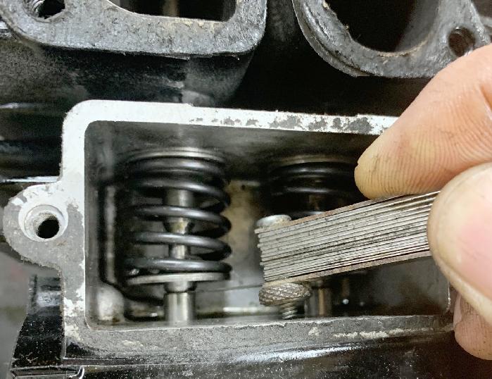
-
If you have more than .006" in gap between the end of the valves
and the top of the lifters, the only thing to do is to buy new
valves (and hope the cam isn't the wear spot!)
But before you go nuts with new valves or welding/grinding, try
switching the two valve lifters. Though technically they are
identical (most of the time, some engines with compression release
cams they are different). This can sometimes fix a cam lash issue.
You could TIG weld the end of the valve, and grind it down to get the proper lash. That would be another technique. I had a particularly worn HSSK50 motor where there was almost .015 valve lash. Yes there were other issues too (like slightly worn valve guides), but figured I could tackle the valve lash issue easily. Used a TIG welded and just welded a dab on the end of the valve. Then using a belt sander, turned the valve as the end of the welded cam turned. Though it doesn't necessarily give you a perfect perpendicular cut, it gets pretty close.
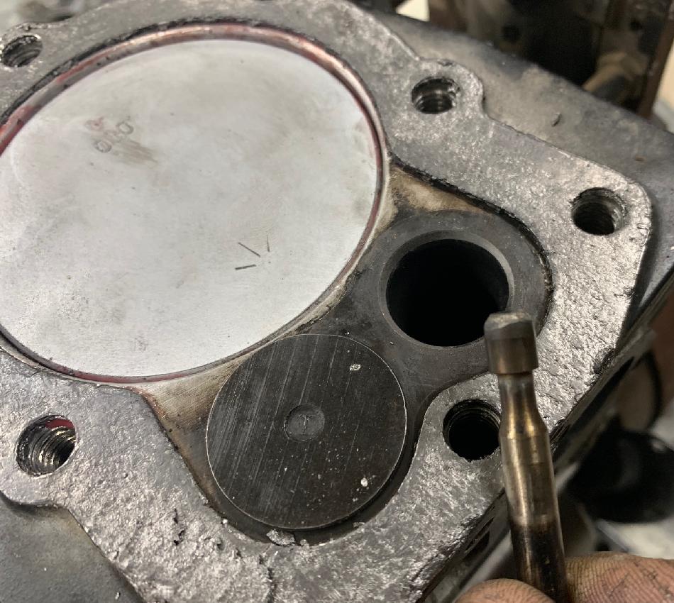
-
After the welded valve end is rough sanded, put it in the motor and
check the lash. You don't have to install the spring to do this.
Hopefully the lash is too little... get it to about .004" or .005" of an inch,
then install the spring and spring keeper. At this point take a small
metal file. Lift the valve up with a screw driver, and put the file
between the valve end and the lifter. Then do some filing. You want
to take that last .001" or .002" off with the file. This will make
sure the end of the valve is nicely perpendicular to the lifter.
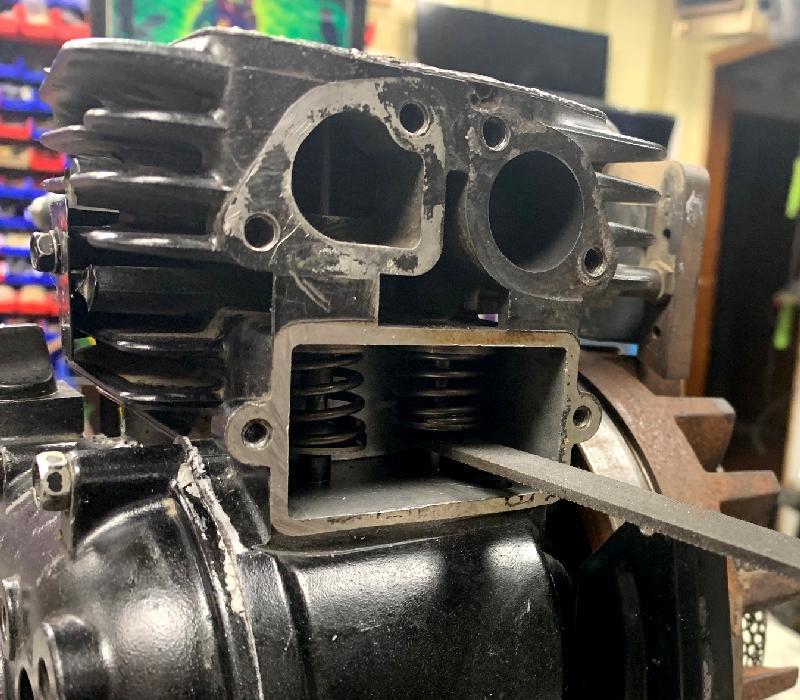
-
Port and Polishing the Valves.
Remember an engine is basically a mover of gases. So technically speaking, the easier gases get in and out of the cylinder, the better performance. For this reason some people port and polish the valve area. Personally I don't do this, as my belief is there's minimal to no increase in performance from doing this on a Tecumseh HS40 or HS50 engine. Some may disagree, but I don't think the "juice is worth the squeeze." And if done incorrectlye you can ruin an engine block.
That said though, since where I'm working on motors has a Dremel grinder one foot away, I do some very mild porting. On the intake and exhaust ports I just round off the sharp edges from the original block casting with a Dremel and a grinding wheel. It only take a moment. But don't go nuts! Like I said it's easy to go too far.
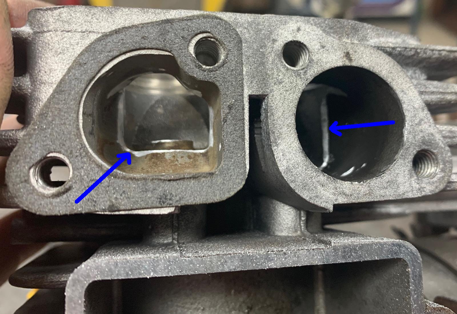
Here's the top view of the ports. Again shiny parts are
where I hit it with the Dremel.
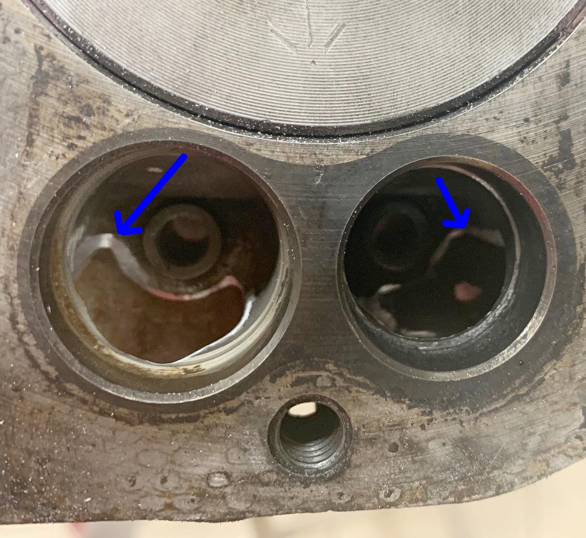
-
Some people even go further and "shave the eyebrows."
There's a video of someone that did this on a Brigg 5hp
on youtube. I really do not recommend this, as it's
just too easy to ruin a block. Also on a Tecumseh
the valve area is very close to the cylinder, so
the advantage to this action on a Tecumseh is minimal
at best.
What about polishing the valve area? On the intake side, you really don't want to polish the valve area. It's only on the exhaust port that a smooth finish can help. But again, on a Tecumseh, the end (minimual) result does not justify the work.
14. The Crankshaft.
-
The standard minibike crankshaft PTO diameter is 3/4 of an inch.
With 3/4", you have the most versatility of clutch and torque converter option.
But a lot of HS50 snowblower motors have 1" diameter PTO shafts.
With a 1" PTO, the choice of clutches is not only more limited,
but more expensive. For this reason, I always use a 3/4" PTO shaft.
But with this in mind, don't discount an otherwise good HS50 engine
with a 1" PTO!
- HS50/HSSK50 crankshaft 3/4" PTO new style taper (CDI): #34740
- HS50 crankshaft 3/4" PTO old style taper (points): #33677 or #34728
- HS50 crankshaft 3/4" PTO old style taper (points) ball bearing case: #33837 (1972-1974, has 3" PTO)
- HS50 crankshaft 3/4" PTO old style taper (points) ball bearing case: #33676 (1972-1980, has 2.3" PTO, replaced #33837)
- HS40 crankshaft 3/4" PTO new style taper (CDI): #34734
- HS40 crankshaft 3/4" PTO old style taper (points): #32877
- HS40 crankshaft 3/4" PTO old style taper (points), ball bearing (Rupp style): #33080
There's a couple ways to deal with this. Either just stay with the 1" PTO, or convert it. If you go on Ebay, you'll find used crankshafts for sale. Just make sure you get the correct one, and that the bearing journals are not worn (easy to see visually). Also between the horsepowers, the crankshafts are not inter-changable. That is, you can't use a HS40 crank in an HS50 engine.
Finally your existing flywheel taper must mate to the crankshaft taper. Just look at the flywheel nut size to make this determination. If it uses a 5/8" socket for the nut, that's the smaller and older style crank with points and condenser. They stopped using the smaller nut crank by late 1980/early 1981. If it uses a 3/4" socket, that's the newer style crank with a different flywheel taper. Some points motors where made with the newer crank taper and larger nut in 1981/1982. Certainly all the CDI electronic ignition crankshaft have the larger flywheel nut and the larger flywheel/crank taper (since CDI came about in 1983). The point being you can't mix the flywheel/crank taper - they have to match.
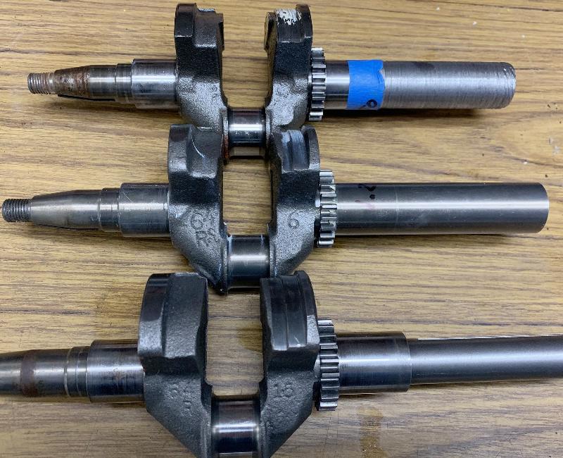
-
There is one more option too, and that's to put your existing 1" PTO crankshaft
in a lathe, and turn it down to 3/4". After you do that, you'll also have to
mill a 3/16" keyway into the crankshaft. Obviously this is work for someone
with a lathe and a mill. Generally it's just easier to buy a new crankshaft
off ebay. But i do this lathe/mill work, and find it quite satisfying.
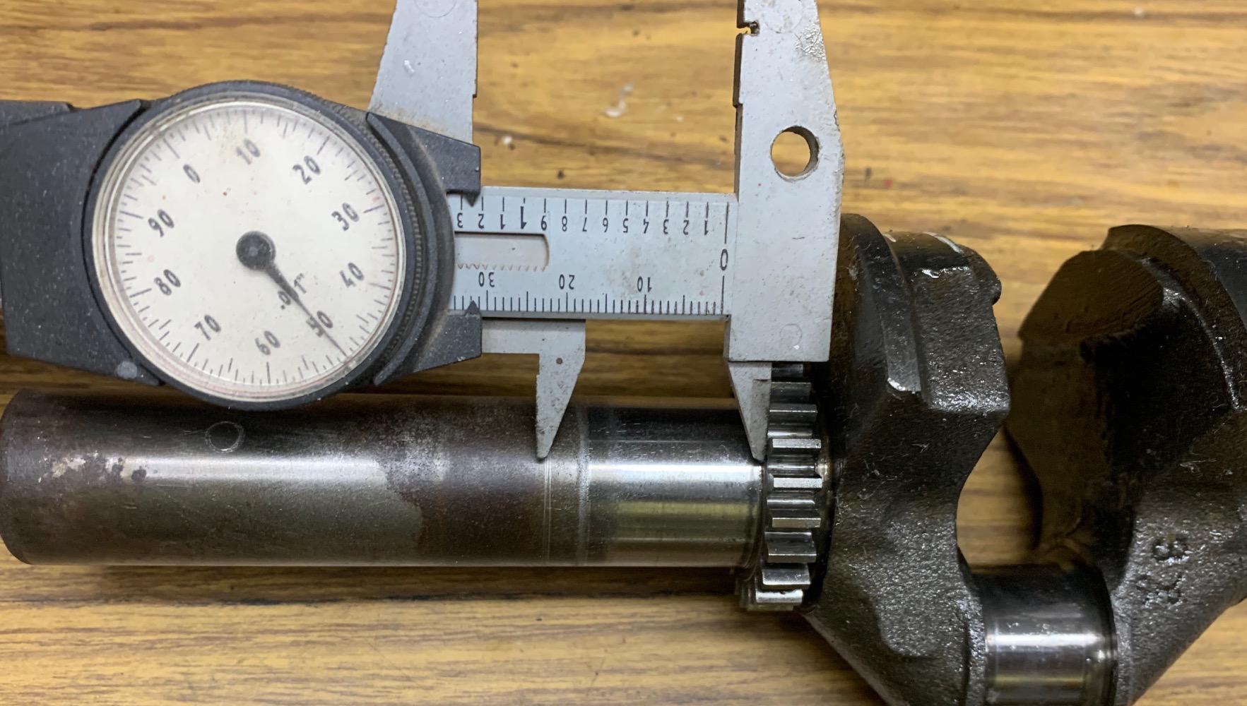
-
One advantage to cutting a 1" PTO down to 3/4" is you'll end up with
a longer PTO. The stock Tecumseh 3/4" PTO is usually 2.25" in length.
But most 1" PTOs are 3" (or close to it.) That's a nice thing to have
if you are running a torque converter.
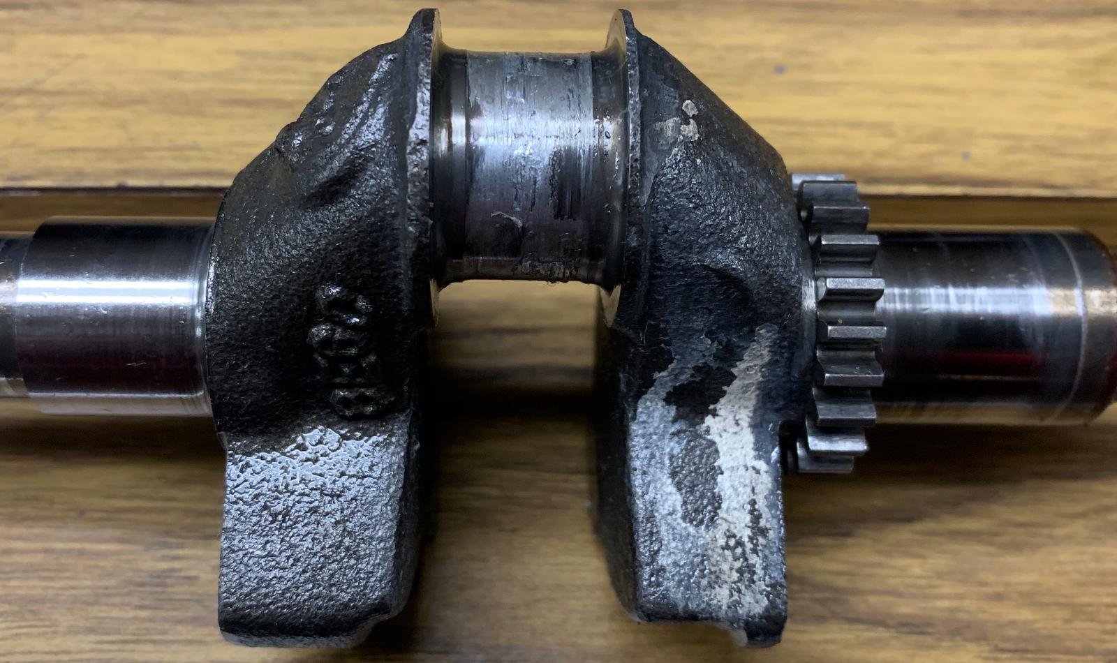
-
If the crankshaft was used in an engine that over-rev'ed, there may be some
aluminum on any of the three crankshaft journals. You don't want to sand
the aluminum off. Instead use muriatic acid, which will basically melt
the aluminum, and leave the steel journal intact. Just use a small paint
brush to apply the acid, wait a few minutes, and it should wipe off. This
may require a few attempts. After all the aluminum is
removed, you can check the journal size with a dial calipher, to make
sure it's still in-spec. Any scratches can be removed with very fine
sandpaper (like 1500 or 2000 grit.) Don't over sand, as you can make
the journal egg shaped.
Also if the journal has aluminum on it, there's a good chance that it's just worn or scratched beyond use. There are some machine shops that will re-weld the journal (to put the worn material back), and then re-cut the journal to the proper size. That's expensive, but some shop can do this. Usually it's just easier to get a new crank.
Note some engines will have a thin washer between the end of the crankshaft and the side cover. This was put there to decrease the amount of end play on the crankshaft. Not all motors will have this washer installed. If it's there, make sure you re-install it. Tecumseh put it there for a reason!
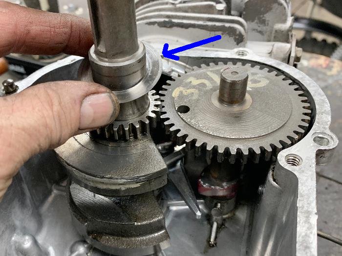
15. Flywheels and Blower Housings (Torque Wench Numbers too).
-
A lot of guys wants to re-create the Tecumseh look of thie 1970s
minibikes, and really want to go that extra mile to do so.
One of the complaints of using a snowblower motor is the
look of the blower housing. Tecumseh H30, H35, HS40 engines
before 1973 have a more rounded blower housing.
Where all HS50 (introduced about 1972) has a more
square blower housing, as do 1973 and later HS40 motors.
What Tecumseh did was change to a single style of blower housing for all their small block motors.
The HS50 was the first model to use the new blower housing shroud #33663. Then the HS40, H35, H30 started to use this new blower housing in 1973 and 1974. The magneto was also changed to match. All the small block motors with squared blower #33663 used the new magneto group #610932, #610940, or #611025, depending on the year built (up to the mid 1980s when CDI took over.)
Also between 1972 to 1974 Tecumseh used small tags on the side of the HS50 block. Because the new #33663 shroud design did not accommodate the aluminum serial number tag used on the older rounded blower housings. It took Tecumseh a while to start pressing serial numbers into the top of the #33663 blower housings, so instead they used small serial number tags on the pre-1975 HS50 engines.
It's a subtle difference, but a lot of hardcore minibike guys can spot the newer mid-1970s square style blower housing over the pre-1973 version from 50 feet. (Heck some guys can even spot the 1968 HS40 blower housing with no "line" below the three head bolt attachments, and no starter mount casting on the front of the case!)
Right: more square 1973 and later HS40 housing.
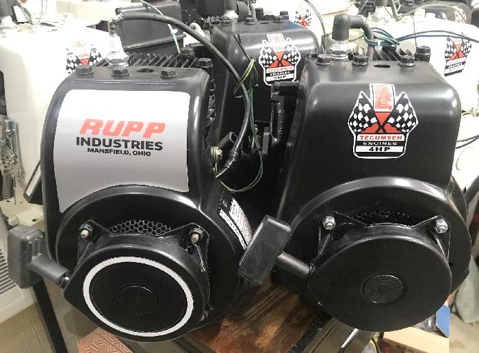
-
I guess the question is... can you take an old round H30 or H35 or HS40 blower housing and put
it on an HS50 motor that had the larger square housing #33663?
You could do this on the A/B/C series HS50 motor versions (pre-1980), but it would require replacment
of the flywheel with a more compact alloy version (HS40 #32517 for a non-lighted engine). It does work
and it gives faster acceleration, as the #32517 flywheel weights less than it's cast iron counterpart.
I don't know the long term issues that may arise. Such as the flywheel
durability on an HS50 and if the round blower housing can keep
the HS50 cool enough. Also remember the start cup will need to be
replaced too with the thinner #590416 cup and the #590417 screen.
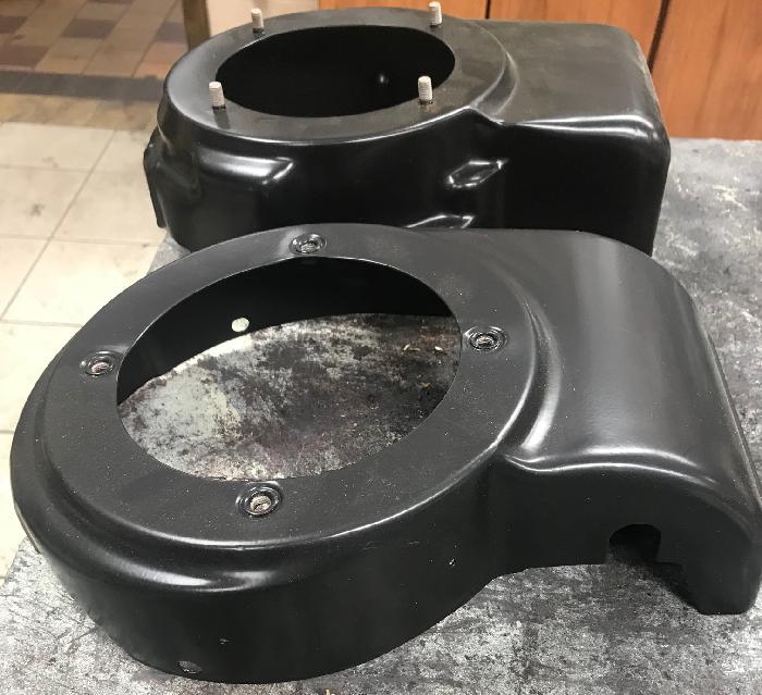
Two round blower housings. The black one (left) is earlier at 1968. The white one (right) is a 1970 version.
Notice the difference? The 1970 version has a pressed ridge at the top, where it bolts to the head.
Also check out the positions of the starter mech nuts. These two blower housings are better for
20 degree mount engines.
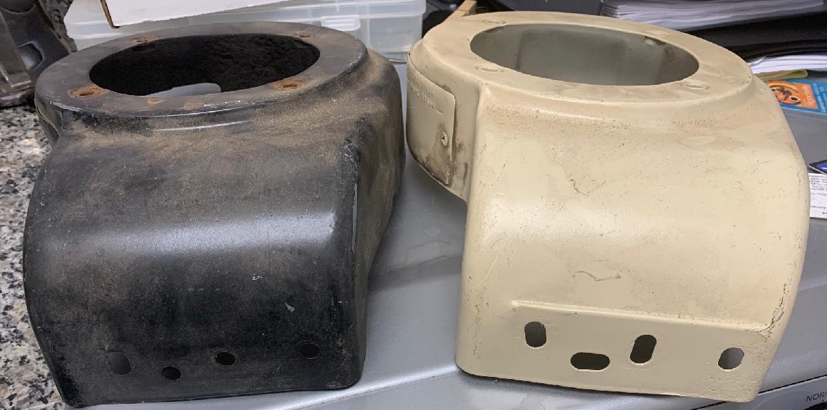
Two different squared HS50 blower housings. The one of the left is a "C" series points
and condenser blower housing. Notice the raised area around the 4 leg pull start. The
one of the right is an "F" series CDI blower housing. Notice the area around the 4 leg
pull start is not raised. This better accommodated the CDI ignition coil. But the blower
housing on the left looks a lot cooler. With some fiddling, the left blower will fit on a
CDI motor without modifications. The CDI coil is close to the blower housing metal,
but it does fit. Cooling is probably not as good to the top of the cylinder however.
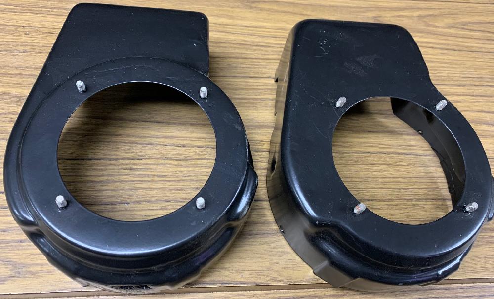
-
Now to discuss flywheels. We touched on this earlier... The snowblower
flywheel almost for certain will be steel, and often with "teeth" (to accommodate
electric start.) Steel flywheels work great to maintain momentum, but since
they weigh a lot, they don't let an engine rev quickly. For minibikes, rev'ing
quickly is probably better than maintaining momentum. For this reason,
stock HS40 minibike motors before 1975 almost always have an alloy flywheel (usually the #32517
alloy flywheel, as used by say Rupp.) On minibike H30 motors they used
an alloy flywheel #31332 (will not fit on HS40 or HS50 motors, as the
crankshaft taper is different.)
But around 1975 Tecumseh pretty much started to use cast iron flywheels for
all their motors.
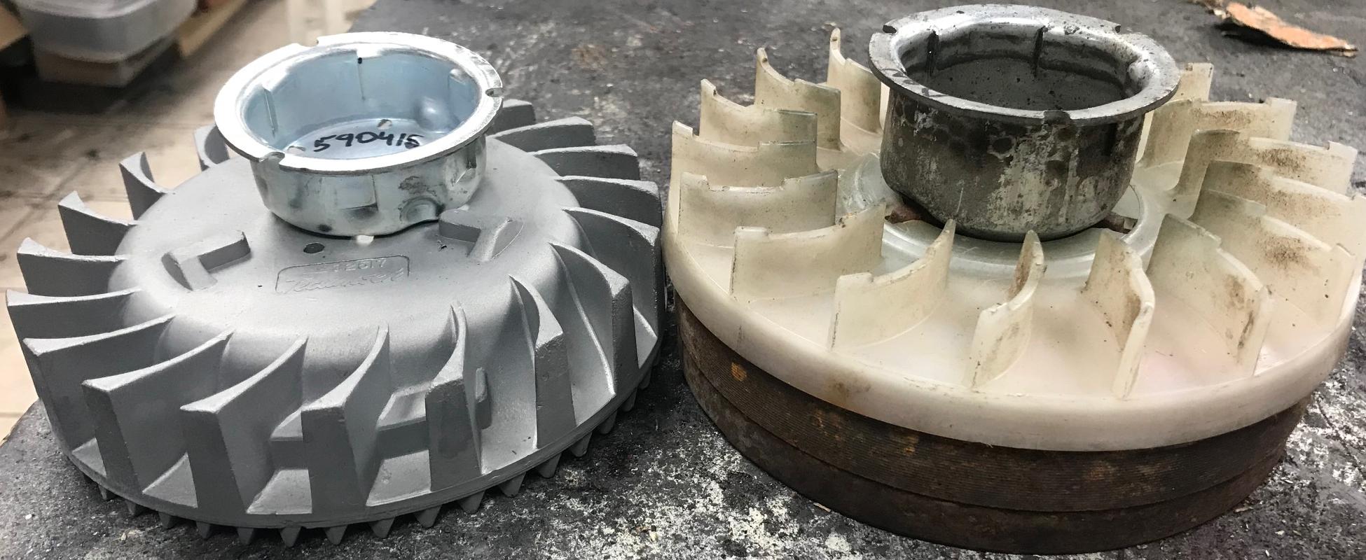
-
In addition, the steel flywheel magnets which are glued into position on
the flywheel, can come loose at higher RPM. If this happens, the magnets
throw and can ruin the coil (and other stuff.) That's why guys that run
at higher RPM like an alloy flywheel (the magnets are secured
differently.) Also it's not a bad idea to check the flywheel magnets
to make sure they are secure.
To check the magnet's glue stability, first use a sharpie and mark the position and magnets themselves. Put marks on the flywheel to show the magnet's position, or run an outline around the magnets. Put an "X" on the side of the magnet. Now use the plastic handle of a screwdriver and hit the magnets. I know that sounds aggresive but you need to do that to make sure that the (30 year old?) glue hasn't given up its hold. If a magnet breaks loose, better now than later! If loose, their spot can be sanded clean with 100 grit sandpaper, and the magnets glued and clamped (while drying) using JB weld. Note the magnet must be glued in exactly the same location and exactly the same orientation. That's why the sharpie marks are handy. North needs to meet the stator plates first during rotation (opposed to south.)
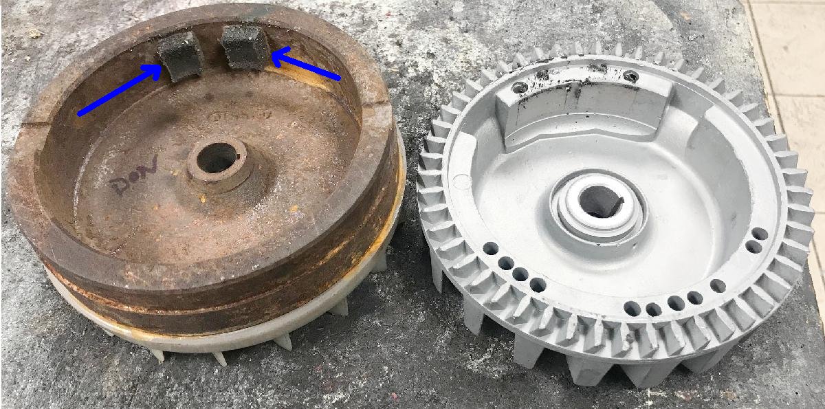
Here's a steel flywheel where the magnets have come unglued from the flywheel.
They need to be re-epoxied back to the flywheel, in the correct position and correct
orientation (north/south). Use JB Weld (24 hour) and a clamp for this task.
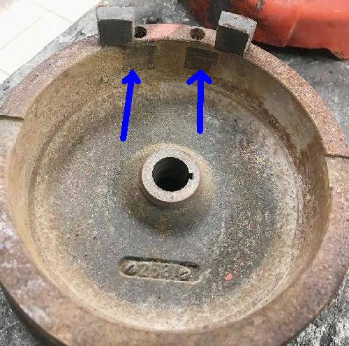
-
With this in mind, can you put an alloy #32517 flywheel on an HS50 motor with
the rounded blower housing? Well if the HS50 motor is points/condenser, yes
you can. But it will require not only the #32517 flywheel and the slimmer rounded
blower housing, but also a different starter cup #590416 and screen #590417. This cup is about 1" tall,
where the steel flywheel's cup is 1.75" tall (which is too tall and won't work
with the rounded housing.) Remember to use a torque wrench and tighten the flywheel
nut (specs below.) And yes all HS50 engines always had the squared blower housing,
even the very first year (1972). Perhaps you're asking if the alloy flywheel really
helps performance? Well the weight is different. The alloy #32517 flywheel weighs about
1850 grams, where the steel HS50/HS40 flywheel (with the plastic fins and the
starter ring gear removed) weighs about 2960 grams.
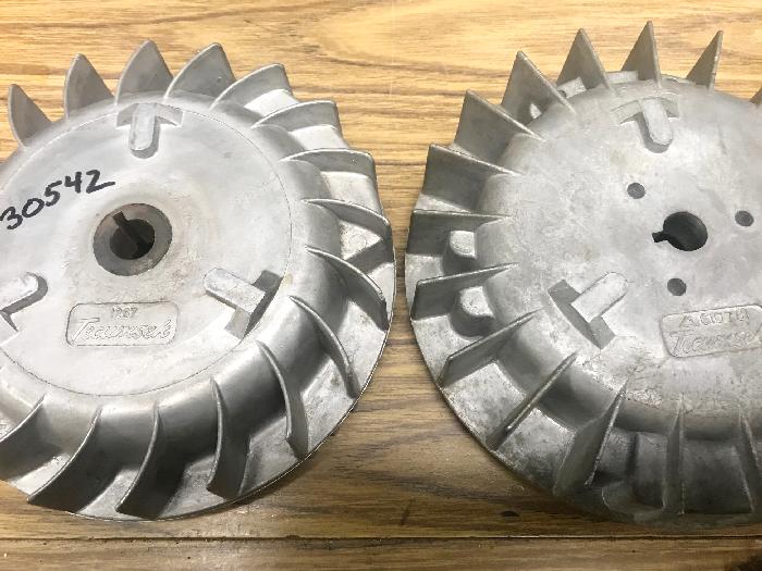
-
There are other points/condenser alloy flywheels out there that will not work. For example
Tecumseh #1267 (aka #30542). This flywheel is significantly lighter in
weight than the #32517 - the #32517 (as used in HS40 minibike motors) has
additional weights around the inside of the flywheel. The #1267 does not have
this added weight, so it's really light. Likewise the #610781 alloy flywheel
is like that too (even lighter than the #1267.) These flywheels are cut for
an H30/H35 crank only (will not work on a HS40/HS50 motor.)
There is also the Tecumseh #610769 points flywheel for the HS40 (uses key 610951) - this
flywheel has many magnets and supports an alternator style magneto
(used on say a Rupp Roadster.) Note there is a lighted Tecumseh H50 flywheel
too #30755.
Oh wait, there's more stuff to consider on rounded blower housings... That is if you are using a lighted Tecumseh engine (one with a magneto that supports lights.) The blower housing on these motors is slightly different. You can used a lighted blower housing on a non-lighted engine. But going the other way (non-lighted housing on a lighted engine) is a bit more tricky.
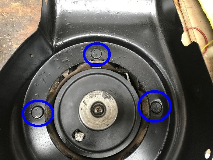
-
The aluminum lighted flywheels (in particular HS40 models) are just slightly thicker than their non-lighted
counterparts in the 1960s to about 1974, before Tecumseh changed to steel flywheels (about 1975).
This is why all lighted HS40 blower housing, pre steel flywheels,
have studs for the starter recoil instead of welded 1/4-28 nuts or rivets to hold the pull starter.
This way nothing is sticking into the shroud. The riveted or nutted versions can be used
on a lighted motors, but you have to thin to nuts to making sure there's clearance
for the fins of the flywheel. And if the blower housing is dented or pushed in
(a common thing on mini bike engines), the situation is even worse. These are
minor details, but something that needs to be considered.
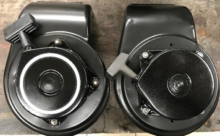
-
Flywheel Keys.
There are basically three types of flywheel keys, which stop the flywheel from rotating on the crankshaft. For points engines, Tecumseh used 1/8" thick flywheel keys with a notch cut out. The notch made the keyway clear the points gaskets. But at some timepoint, Tecumseh made the points gasket with a larger hole, so the flywheel key cut out wasn't needed. And with the change to CDI, the keyway cut out was definitely not needed.
In regards to the cut out flywheel key, at some point Tecumseh changed their mind on this keyway, and made the cut out smaller. These two key are 610961 and 610951. The 610961 has the deeper cut out. Personally I used the 610951 key. When Tecumseh switched to CDI ignition flywheels, the key changed to a standard rectangle 1/8" thick key with no cut out #611298.
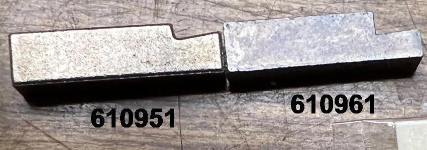
-
Snowblower Flywheel Starter Gear.
If you are using a snowblower motor 1975 and later, often they will have the option for an electric start on the cast iron flywheel. This is something not needed on a minibike. The starter gear on the cast flywheel is removable. Originally they heated up the gear and slid it onto the flywheel. It looks like it's cast onto the flywheel, but it is not.
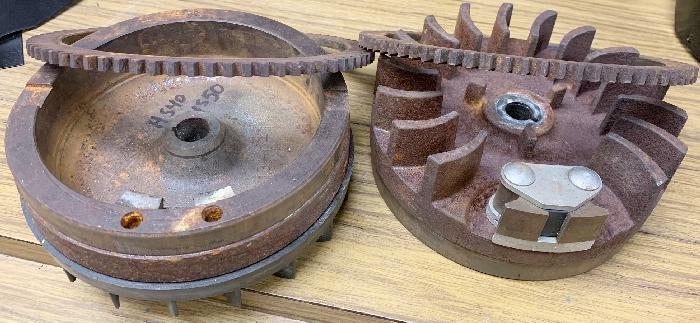
-
I usually remove this starter gear as it just adds weight to the flywheel.
There's a couple ways to get it off. I use a press. But you can also use
a cutoff wheel on a hand grinder (Metabo), and cut the gear (don't cut into the flywheel!)
Either way, the gear does come off. Having a lighter flywheel will give (in theory)
better acceleration, that's why I remove it. On the other hand, if you're using
a flywheel puller, with no starter gear it's hard to remove the flywheel with
a puller.
- HS40 alloy #32517, points (1968-1974): 1850 grams
- HS50 alloy #33659, points (1972-1974): 2993 grams
- H35/HS40/HS50 cast iron, #611029 or #33701, points, starter gear removed (1975-1983): 2960 grams
- H35/HS40/HS50 cast iron, #611029 or #33701, points, starter gear (1975-1983): 3360 grams
- H35/HS40/HS50 cast iron #611081, CDI, no starter gear (1983-2008): 3210 grams
Flywheel Weights.
For a comparison, here's the flywheel weights in grams. The HS40 aluminum flywheel
is definitely the lightest. Does this make a difference in performance? Some say it
does. My opinion on this is "maybe". Note the 1972-1974 alloy HS50 flywheel is actually
about 30 grams heavier than it's 1975 and later cast iron brother (assuming the starter gear is cut off.)
Rounded Blower Housing on the HS50.
So can you use the rounded blower housing on an HS50? Maybe... you would
need an HS50 model A,B,C (pre-1980.) This is the 16 degree flywheel taper (with an 11/16"
socket nut holding the flywheel in place.) Starting with the D series of HS50 engines,
the flywheel taper changed to 10 degrees (and the flywheel nut to a 3/4" socket), which
won't allow the #32517 flywheel to work. Assuming you have the correct HS50 engine,
to do the conversion you will need a flywheel #32517, starter cup #590416, cup screen #590417, and a round
blower housing. With these parts, you can make an HS50 look like a pre-1973 HS40.
This is ideal if you are say restoring a 1972 Rupp minibike that used an HS40... but now you
have the advantage of an HS50 engine with the look of a 1972 and earlier HS40.
16. Torque Wrench Numbers and Engine Specs.
-
All this information came from the
1998 Tecumseh Technicians L-head Service Manual.
- Steel Flywheel nut: 550 inch/pounds or 46 foot/pounds
- Alloy Flywheel nut: 450 inch/pounds or 37 foot/pounds
- Cylinder head bolts: 200 inch/pounds or 16.5 foot/pounds
- Spark plug: 250 inch/pounds or 21 foot/pounds
- Engine side sump cover: 115 inch/pounds or 9.5 foot/pounds
- Connecting rod bolts: 105 inch/pounds or 8.5 foot/pounds
- Ring gap end: .007" to .017" (points/condenser motors)
- Ring gap end: .010" to .020" (solid state motors)
- Displacement (in�): 10.49
- Stroke: 1.938
- Bore: 2.625 to 2.626
- Timing Dim. BTDC: .035
- Valve Clearance: .004 to .008
- Valve Seat Width: .035 to .045
- Valve Guide Oversize Dim.: .2807 to .2817
- Crankshaft End Play: .005 to .027
- Crankpin Journal Dia.: .9995 to 1.0000
- Crankshaft Mag. Main Brg. Dia.: .9985 to .9990
- Crankshaft PTO Main Brg. Dia.: .9985 to .9990
- Camshaft Bearing: .4975 to .4980
- Conn. Rod Dia. Crank Brg.: 1.0005 to 1.0010
- Piston Diameter Bottom of Skirt: 2.6202 to 2.6210
- Ring Groove Side Clearance (1st/2nd Comp.): .002 to .005
- Ring Groove Side Clearance (Bottom Oil): .001 to .004
- Piston Skirt Clearance: .0040 to .0058
- Thick Ring End Gap: .007 to .017
- Cylinder Main Brg.: 1.0005 to 1.0010
- Cylinder Cover/Flange Main Bearing Dia.: 1.0005 to 1.0010
- Displacement (in�): 10.49
- Stroke: 1.938
- Bore: 2.625 to 2.626
- Valve Clearance: .004 to .008
- Valve Seat Width: .035 to .045
- Valve Guide Oversize Dim.: .2807 to .2817
- Crankshaft End Play: .005 to .027
- Crankpin Journal Dia.: .9995 to 1.0000
- Crankshaft Mag. Main Brg. Dia.: .9985 to .9990
- Crankshaft PTO Main Brg. Dia.: .9985 to .9990
- Camshaft Bearing: .4975 to .4980
- Conn. Rod Dia. Crank Brg.: 1.0005 to 1.0010
- Piston Diameter Bottom of Skirt: 2.6202 to 2.6210
- Ring Groove Side Clearance (1st/2nd Comp.): .002 to .005
- Ring Groove Side Clearance (Bottom Oil): .001 to .004
- Piston Skirt Clearance: .0040 to .0058
- Thin Ring End Gap: .010 to .020
- Cylinder Main Brg.: 1.0005 to 1.0010
- Cylinder Cover/Flange Main Bearing Dia.: 1.0005 to 1.0010
- Displacement (in�): 12.04
- Stroke: 1.938
- Bore: 2.812 to 2.813
- Timing Dim. BTDC: .035
- Valve Clearance: .004 to .010
- Valve Seat Width: .035 to .045
- Valve Guide Oversize Dim.: .2807 to .2817
- Crankshaft End Play: .005 to .027
- Crankpin Journal Dia.: .9995 to 1.0000
- Crankshaft Mag. Main Brg. Dia.: .9985 to .9990
- Crankshaft PTO Main Brg. Dia.: .9985 to .9990
- Camshaft Bearing: .4975 to .4980
- Conn. Rod Dia. Crank Brg.: 1.0005 to 1.0010
- Piston Diameter Bottom of Skirt: 2.8072 to 2.8080
- Ring Groove Side Clearance (1st/2nd Comp.): .002 to .005
- Ring Groove Side Clearance (Bottom Oil): .001 to .004
- Piston Skirt Clearance: .0040 to .0058
- Thick Ring End Gap: .007 to .017
- Cylinder Main Brg.: 1.0005 to 1.0010
- Cylinder Cover/Flange Main Bearing Dia.: 1.0005 to 1.0010
- Displacement (in�): 12.04
- Stroke: 1.938
- Bore: 2.812 to 2.813
- Valve Clearance: .004 to .008
- Valve Seat Width: .035 to .045
- Valve Guide Oversize Dim.: .2807 to .2817
- Crankshaft End Play: .005 to .027
- Crankpin Journal Dia.: .9995 to 1.0000
- Crankshaft Mag. Main Brg. Dia.: .9985 to .9990
- Crankshaft PTO Main Brg. Dia.: .9985 to .9990
- Camshaft Bearing: .4975 to .4980
- Conn. Rod Dia. Crank Brg.: 1.0005 to 1.0010
- Piston Diameter Bottom of Skirt: 2.8072 to 2.8080
- Ring Groove Side Clearance (1st/2nd Comp.): .002 to .005
- Ring Groove Side Clearance (Bottom Oil): .001 to .004
- Piston Skirt Clearance: .0040 to .0058
- Ring End Gap: .010 to .020
- Cylinder Main Brg.: 1.0005 to 1.0010
- Cylinder Cover/Flange Main Bearing Dia.: 1.0005 to 1.0010
- Displacement (in�): 11.09
- Stroke: 1.938
- Bore: 2.795 to 2.796
- Valve Clearance: .004 to .008
- Valve Seat Width: .035 to .045
- Valve Guide Oversize Dim.: .2807 to .2817
- Crankshaft End Play: .005 to .027
- Crankpin Journal Dia.: .9995 to 1.0000
- Crankshaft Mag. Main Brg. Dia.: .9985 to .9990
- Crankshaft PTO Main Brg. Dia.: .9985 to .9990
- Camshaft Bearing: .4975 to .4980
- Conn. Rod Dia. Crank Brg.: 1.0005 to 1.0010
- Piston Diameter Bottom of Skirt: 2.790 to 2.791
- Ring Groove Side Clearance (1st/2nd Comp.): .002 to .005
- Ring Groove Side Clearance (Bottom Oil): .001 to .004
- Piston Skirt Clearance: .0040 to .0058
- Thin Ring End Gap: .010 to .020
- Cylinder Main Brg.: 1.0005 to 1.0010
- Cylinder Cover/Flange Main Bearing Dia.: 1.0005 to 1.0010
Torque Wrench Specs:
HS40 Points/Condenser Engine Specs.
HS40 CDI Solid State Engine Specs.
HS50 Points/Condenser Engine Specs.
HS50 (G and earlier) and HSSK50 (M and earlier) CDI Solid State Engine Specs.
HS50 (H and later) and HSSK50 (N and later) CDI Solid State Engine Specs.
Note this is when Tecumseh went to a slighter smaller bore on the HS50 and used
thin rings on the piston. Also the exhaust valve was reduced in size. This happened
in the early to mid 1990s. This is a big deal as you can't use an earlier piston
or rings in these newer HS50/HSSK50 motors. The piston skirt size was reduced from 2.807" (old) to
2.790" (new). And the cylinder bore was reduced from 2.812" (old) to 2.795" (new).
17. Dipstick, Oil Plug, Spark Plug.
-
Often the oil dip stick used on snowblowers is a high and tall
version, which screws into the top of the oil sump side case, and stick up about ten inches.
This just won't work for a minibike. But the good new is,
it's an easy situation to fix. Just order a new Tecumseh
dipstick #31297 (which is the ideal replacement), or #37884
(which will require a new 'full' line). The #31297 is ideal, as
it's the closest dipstick I've found for this application.
Unscrew the existing tall dipstick assembly and discard.
Screw in the new replacement. If you need a new gasket,
that's part number #29673. Note on low oil fill plugs, you should
*always* replace the #29673 gasket. They wear out, and oil will
leak onto the garage floor if it's not replaced!
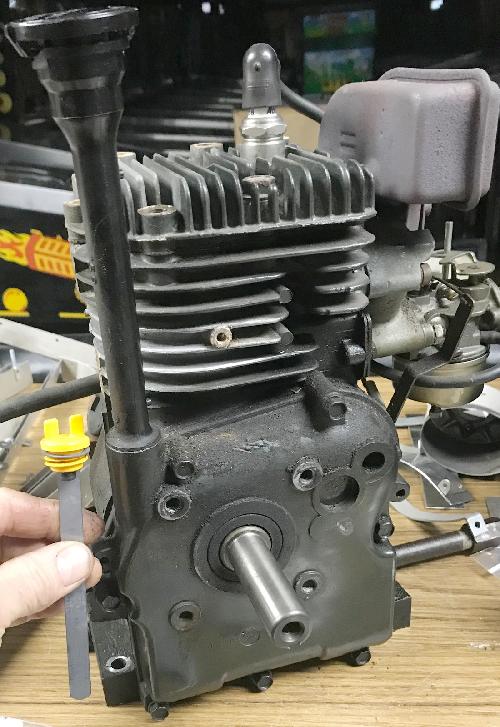
-
The dipstick #31297 is pretty much perfect, but not always easy to find.
The dipstick #37884 works well too, but it's oil range is slightly
different than the original dipstick. With oil in the engine you can
fill the crankcase with the old dip stick to 'top', and then compare
with the new dip stick. You can scribe a new 'top' line on the
new dip stick if you desire.
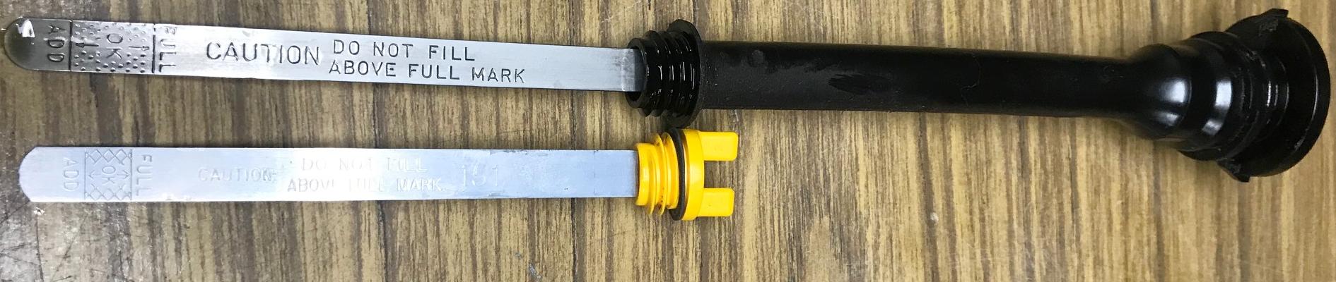
New dipstick #37884 is marked and ready for use!
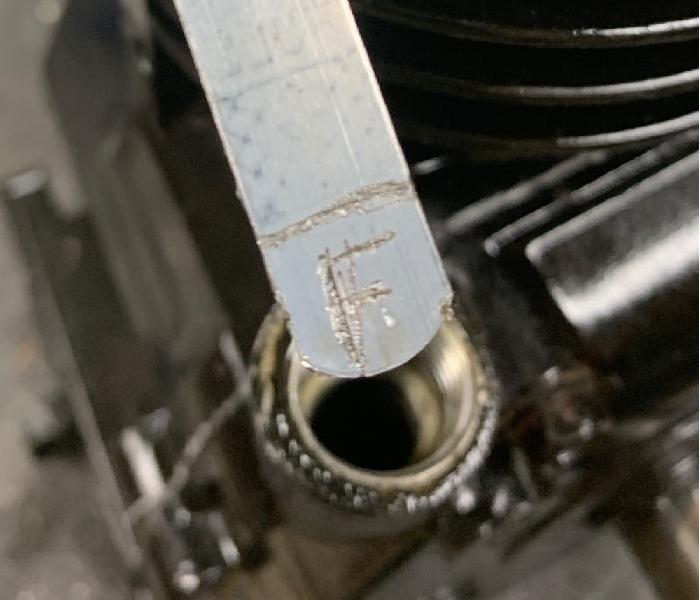
Proper oil fill "full" mark is two inches from the bottom edge of the side case.
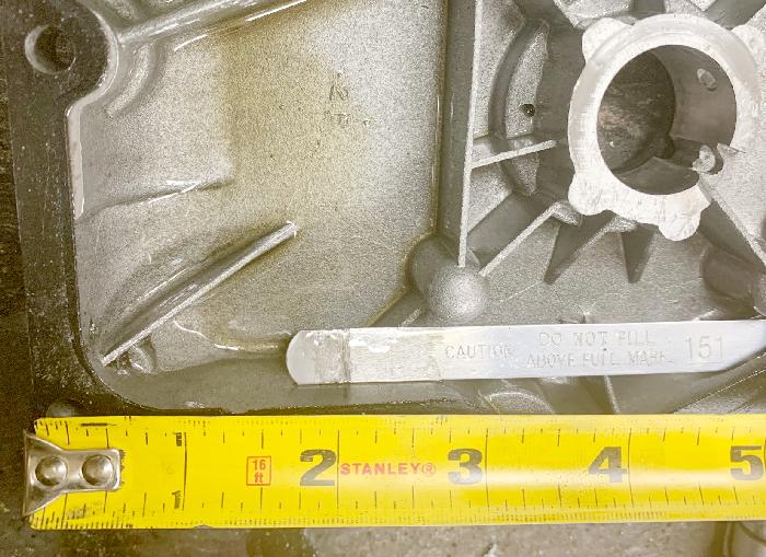
-
You can also measure two inches from the bottom of the side case to check
the new oil fill mark. This new dip stick is obviously a lot more elegant than the
old snowblower style set up.
Next up is the oil plug. Some snow blowers have extra long oil plugs/drains. This is great for a snow blower, but not so great for a minibike. But the good news is, it's easy to convert this to minibike style.
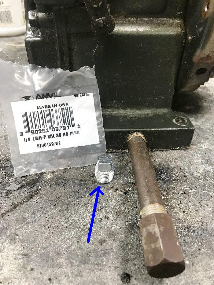
-
Any hardware store in their plumbing department will have these oil plugs.
They are 1/4" NPT plug. Just buy one and replace the extended snow blower
drain plug with the new NPT plug.
The oil used in these is generally 10w-30. Many insist that it be non-detergent oil, as it does not foam. But if you have your motor apart, I like to fill the crankcase before I attach the side cover. Fill it just to the top of the crankshaft (as seen in the picture below.) Then install the side cover and torque the attachment bolts. Set the motor in the normal position, and see if you get any oil leak on the bottom.
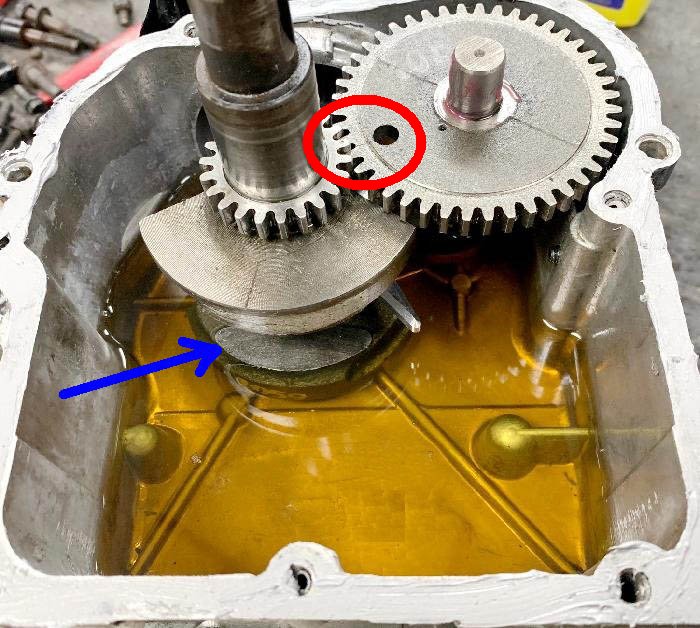
-
Spark Plug for Tecumseh.
- J19LM (Heat range 9)
- J8C or short version CJ8 (Heat range 8)
- J17LM (Heat range 7)
The spark plug is obviously important on these motors too. Generally Tecumseh motors came with a Champion sparkplug. You have a choice of three Champion spark plugs to use:
Listed these from high to low temperature. The Champion J17LM is typically the plug for a Tecumseh HS40. But most people seem to use the Champion J8C (or the shorter CJ8 if there's clearance problems with the frame.) Another plug I really like is the Autolite 255 (another short plug like the CJ8.) The gap should be .030" on any spark plug used. Note that plugs come in different lengths. For mini bike usage, I like the 'short' plugs (like the Autolite 255 or Champion CJ8), as it is less likely to interfere with the top tube of the frame.
After running the engine for a bit, you can remove the current spark plug and check it's color. It should be a nice gray. If it's white, that's too hot. If it's black, that's too cold. You can adjust the plug (or jetting) used to compensate for this.
18. Installing the Minibike Throttle Assembly and Gas line.
-
The snowblower throttle assembly will not work for a minibike application.
Sure you can probably hack the original snowblower throttle to work, but I really
do not suggest this. Especially since a new minibike throttle assembly is
only about $20, part #730136a. Lots of places sell this online, just buy one.
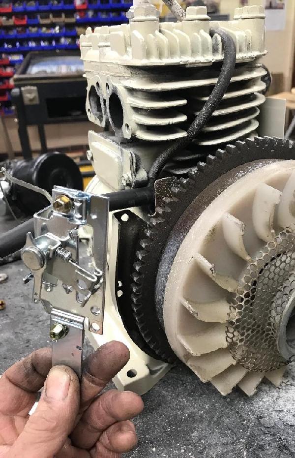
-
First you'll need to remove the old snowblower throttle assembly. I use a 3/16"
drill bit, and drill out the two rivets holding the old assembly in place.
If you still have the flywheel removed (from the points/condenser servicing),
this is perhaps a bit easier. But if the flywheel is in place, that's fine too.
Again you can do all this work with the flywheel installed, but if the flywheel is removed, it is a bit easier. (It is a bit easier to install the new fuel line too when the flywheel is removed.) Install the new throttle assembly using two #8-32 bolts with nylon lock washers. The kit comes with bolts, but personally I like nylon lock washers better than what they supply.
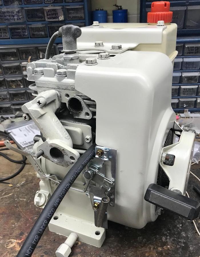
-
Also if you are running a engine mounted gas tank, install a new 1/4"
fuel line. Don't be cheap!! Buy brand new fuel line. It's not worth messing
around with, just get new fuel line. I prefer the original style black
double walled variety myself.
Now is the time to re-install the blower housing. There are two bolts on either side, plus the three head bolts that hold the blower housing in place.
19. Pull Start Mechanism Maintanence.
-
If you're doing powder coating, you will have to take the pull
start mech completely apart (plastic will melt otherwise!)
That's a ballsy move, and one I generally don't take. Instead
I usually paint the pull start mech (assuming it doesn't need
a new spring.) I just thought I would mention that...
Since the blower housing is installed now, it's time to address the pull starter mech. If it works fine, then I guess you're done. But in my experience, this assembly always needs some work.
First thing is to make sure you have a proper pull start handle. A lot of snowblowers use a big plastic handle, and frankly this just isn't going to work on a minibike. The correct Tecumseh rubber pull start handle is part #590387. These are available at many online sources and frankly are pretty cheap. It's nice to have a new one.
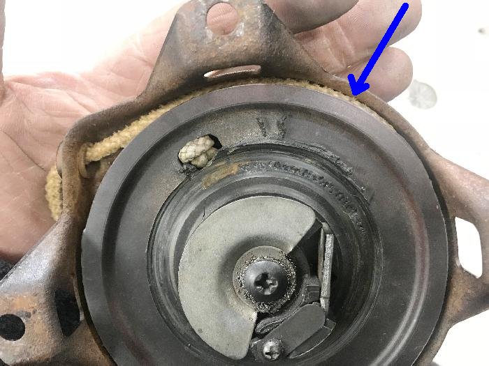
-
Next up is to address the pull cord. Originally the Tecumseh
pull cord is 11/64" nylon cord on older pull starts. Personally I use slightly
smaller 5/32" nylon cord. Why? because I find that the larger
cord size can get wedged between the moving plastic wheel
and the stationary metal housing. This makes the pull starter
"stick", which is really irritating. Because of this I replace
the pull rope with 5 feet of 5/32" nylon cord.
It sucks when the pull cord is too short,
and jams your shoulder when you pull one with a short rope.
Tecumseh recommends 54" for the pull length
on the old 4 leg style pull starters. I generally go with 5 foot (60 inches)
because I always end up with extra on the ends after I make the knots.
To replace the pull rope is pretty easy. Just pull the handle until all the cord is out of the housing. Then jam a flat head screwdriver between the plastic wheel and the stationary housing. Now you can cut off the old rope and install the new rope section. Don't forget to melt the ends of the new nylon rope so it does not fray. I use three knots at both ends.
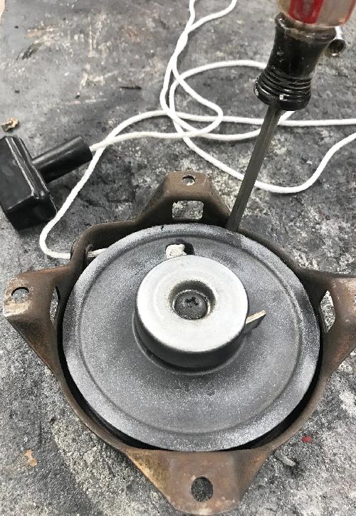
-
After the new rope is installed, there may not be enough spring
in the pull start to suck all the rope into the housing. This is
easy to deal with too. Just pull out about 1/4 of the rope length,
then wind the extended rope around the plastic wheel. That will
take up the slack.
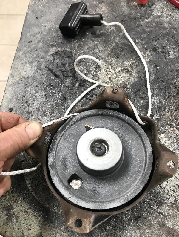
-
With the new rope length installed, you can install the pull
start mech onto the blower housing. Note on old pull start handles,
the hole in the metal U channel is sometimes hogged out. Another
good reason to replace the pull handle with a new #590387 assembly.
But you can take a hammer is make the hole in the metal U channel
smaller, if needed.
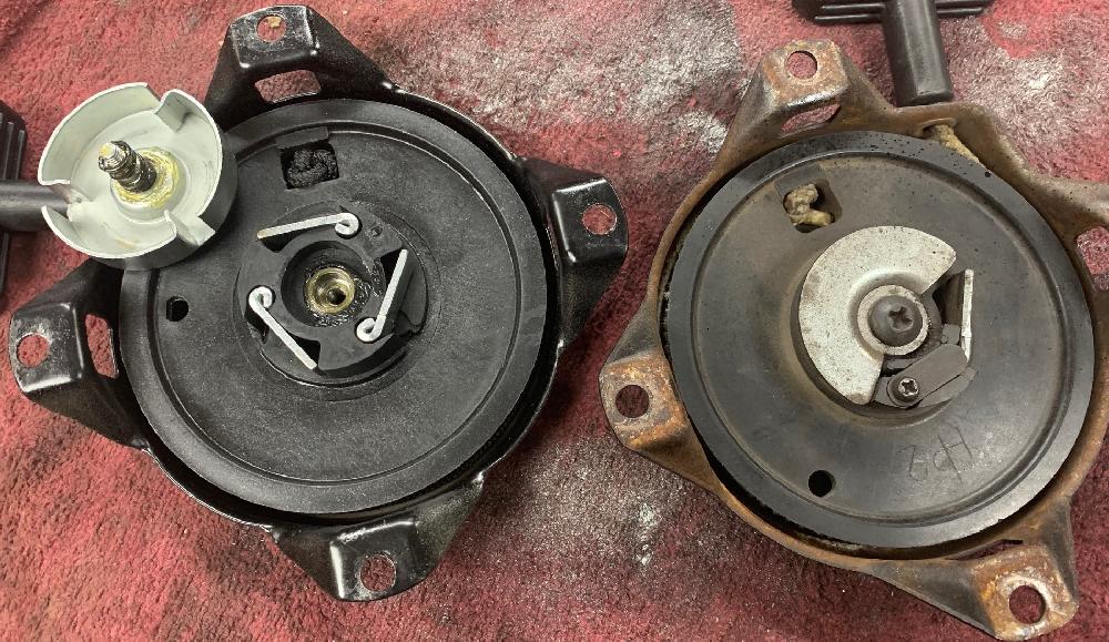
-
I've seen on ebay some reissue new 4 leg starter assemblies for
about $20. These are actually pretty good quality. But there's one
caveat... they use three "dogs", instead of just one like the original
starters. The problem is, these three dogs don't seem to catch the
inside of the flywheel starter cup correctly. When you pull the rope,
the starter doesn't catch the flywheel cup and it "skips". This can
really hurt your shoulder and make starting the engine difficult.
To fix this, just remove the top dog cup (5/16" bolt), and remove two of the dogs and their spring. Save these parts by the way! (They can come in handy when repairing an original starter.) With one dog, these reissue starters seem to work a lot better.
20. Starting the Engine for the First Time.
-
Now you have your basic "long block" all ready. You have done some
modifications perhaps (governor, etc.), and maybe new rings and/or
lapped the valves. You have the magneto all set with good points and
a new condenser. The flywheel is sorted out and installed too. The dipstick
(and oil!) are installed, as is the blower housing and pull start. The
only thing left to do is the carburetor and the exhaust, right?
Well now is the time to make sure you have a good viable engine. It's time for the first run, to make sure you've done everything right up to this point.
You can use a compression tester to test for compression. I bought one on ebay for about $30 and it seems to work well. Screw in the brass fitting to the spark plug, and pull the cord. It will record the highest compression the motor can generate. It seems like anything over '50' is a good viable engine.
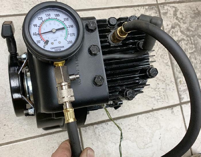
Using a compression tester on an HS50 engine. This is where it should be!
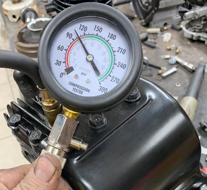
-
In order to test the engine, you will need some starter fluid, aka ether.
This can be purchased at nearly any hardware store or even many gas stations.
Auto parts stores should have it too. It comes in a spray can.
There's a couple ways to do this. Have the motor on the ground, on a firm surface. Spray the ether into the intake port. A good one or two second squirt. Then put your foot on the top of the blower housing, and pull the starter cord. The engine should fire up for about one second.
Another way, my personal favorite, is to remove the spark plug, and then spray the ether into the head through the removed spark plug. Then quickly replace the spark plug (finger tight is fine) and spark plug wire, and with your foot on the top of the blower housing, pull the starter cord.
(starting fluid), which was sprayed into the spark plug hole. You will only
get about one second of running time like this. But it demonstrates that
the engine has spark and good compression.
-
In either case, the motor should start for about one second, in a full
throttle type rumble. This is enough to tell that you have:
1) proper compression, 2) spark. With this confidence builder, the
only thing left to figure out is the carburetor!
21. Carburetor (stock style).
-
With the blower housing installed and everything tidy, it's time
to deal with the carburetor. Forget the original carb that
came with the snowblower, it's not a good fit here. Just throw it
away and forget it.
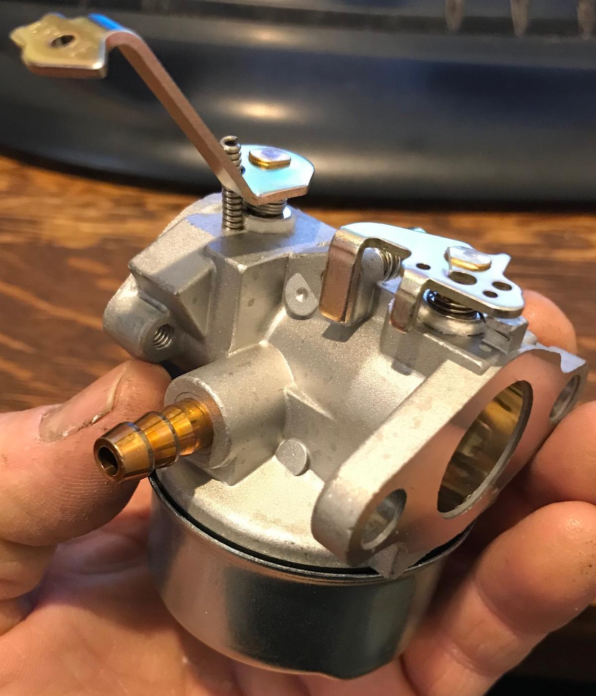
-
I've experimented with many different
carbs on Tecumseh HS40 and HS50 engines. What I have found is the
Tecumseh replacement carb #632230/632272 availabe on ebay work great.
They are really inexpensive (about $10 or so), and they work well.
The choke lever is a nice fit for a minibike application. And the
general openings of this carb work really well for a minibike.
But there are a couple modifications needed to make this carb
work best for a minibike application. Note another carb people
like to use is #631918. Personally I do not like this carb as
much, as the choke lever is rather long, and it has smaller
internal orifices (less performance.) But of course you
can bend that choke lever to fit your application. The 631918 carb does have
a nice 90 degree gas intake though.
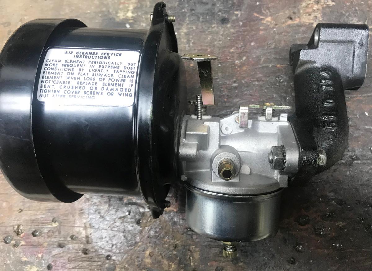
-
You will also need an air filter for the new carb. The snowblower
did not originally have any air cleaner (why would you need one
in the snow?) Luckily a new Tecumseh minibike style air cleaner
is available. It consists of three parts: The mounting plate (#31691 or #31914 offset version),
the body (#31715), the air filter itself (#30727), and gasket (#27272A). Or you can
buy the entire assembly (#730127), or even the expensive version entire assembly (#730164, comes
with both mounting plates and the filter). Note when doing your powder coating it's
best to have the air filter body and mounting plate powder coated too!
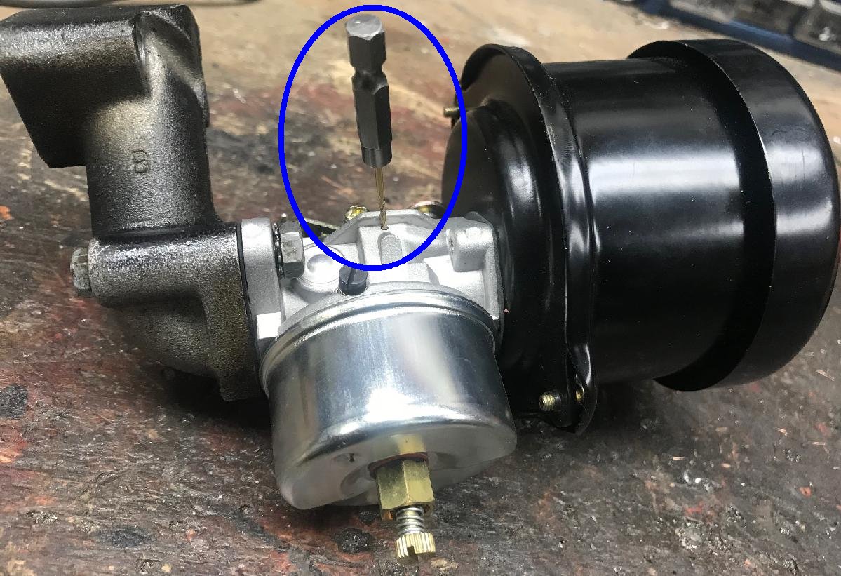
-
With the ebay Tecumseh carb #632230, the breather hole on the side of
the carb needs to be opened up. This hole allows the fuel bowl to breath.
Use a 1/16" drill bit and widen the hole.
The bit only need to go in about 1/4" (you will feel it go through.)
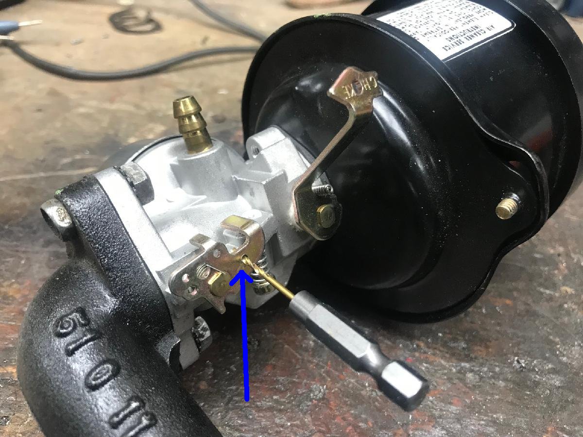
-
Note the Asian made Tecumseh carbs do vary a lot. Lately I've noticed the
style show below with the vent hole are no longer present.
Instead they have move to a different style... It has no side vent hole (so you can't/don't
enlarge anything), and instead has a brass vent pointing towards the
air filter. This style of replacement Tecumseh carb works great too.
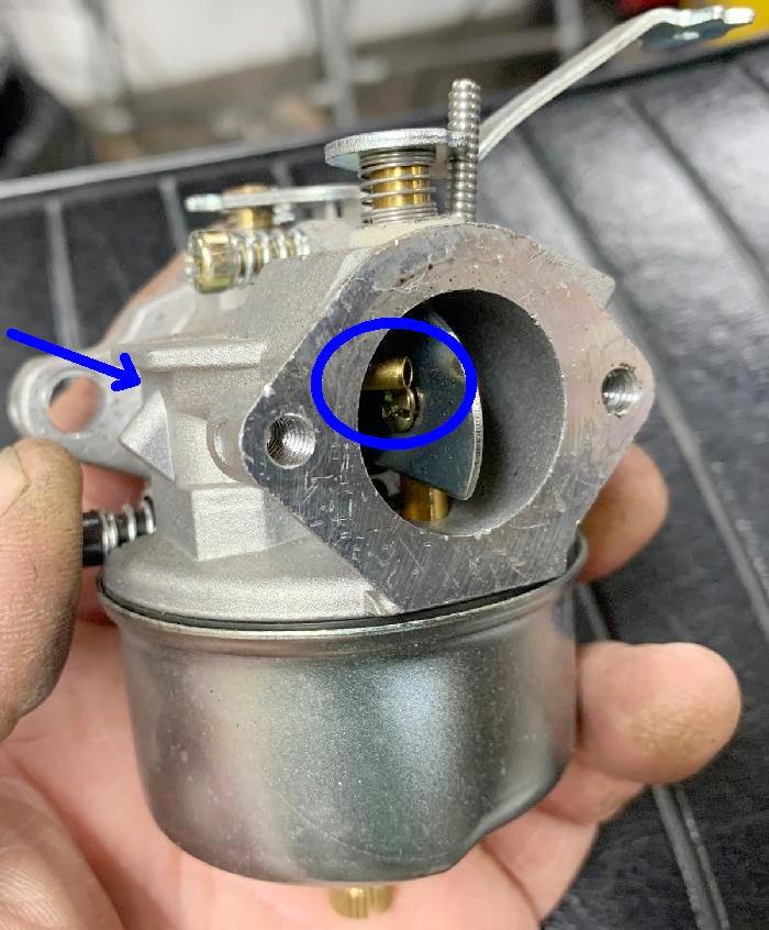
-
Second modification is to add a 1/16" hole to the butterfly throttle control.
This is needed for the throttle arm. It makes the throttle work better
than the existing factory drilled holes.
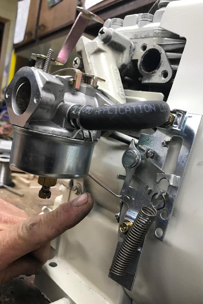
-
With these modifications you can bolt the carb/air filter in place
and connect the throttle control wires. I use Piano wire and make
new control wires. But usually you can use the stock existing ones.
From the new throttle control assembly we installed in the prior
steps, there should be a spring to the throttle control arm. If you
have deleted the governor, this should now be a straight wire.
Even if you didn't delete the governor you can still use a straight
wire here. That will essentially delete the governor too (though all
the internal governor parts will be working against the wire!)
It's not ideal, as the internal governor gear won't like this modification.
But it does work to defeat the governor, until you have time to remove
the governor correctly.
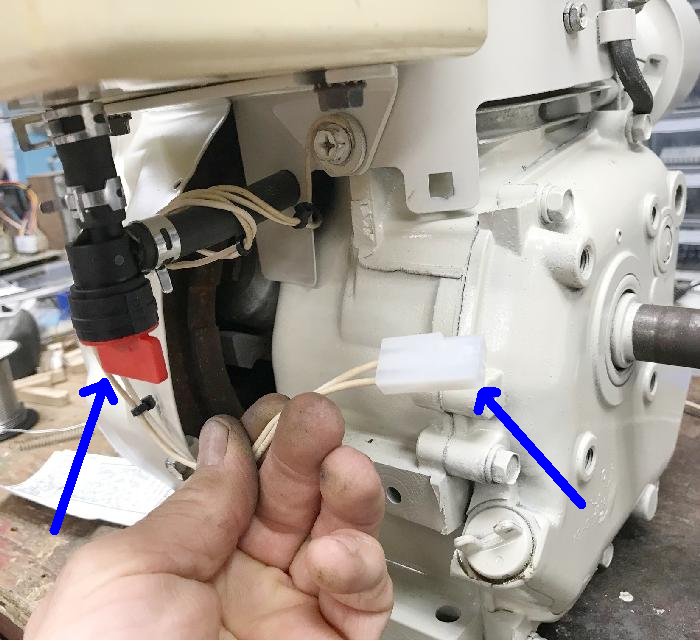
-
Now is a good time to install the gas tank (I assume you are using
a motor mounted gas tank.) I get a fuel shut off value for the gas
tank, as you will probably need that at some time, if you ever
have to work on the carb. Highly recommended.
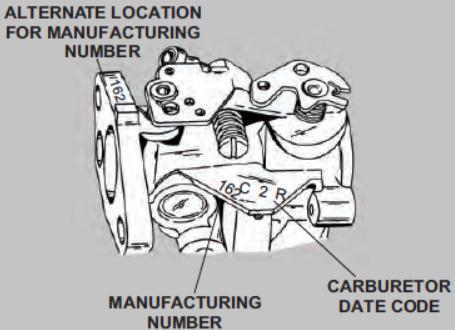
-
Original Carbs.
If you are not using a snowblower motor, and are rebuilding an original minibike motor, some people may want to use the original carb. Of course it will need to be rebuilt (which may end up costing more than just buying a brand new carb!) But for those that this matters (or if your motor uses a diaphragm carb, for which there are not cheap replacements), a rebuild may be in order. To do such a thing you will need the carb part number. You may think Tecumseh just put the part number on the carb, but you would be wrong. It's a coded system. There's a short 1 to 4 digit number which transcribes to a longer 5 to 7 digit actual part number. Then with the actual part number, you can buy the appropriate rebuild kit. Once you have the carb number identified, you can reference the Carb Id Document and get the actual carb part number. Another nice document shows how to rebuild a carb.
If you have a minibike motor from 1969 to early 1971 that was originally on a slanted 20 degree motor mount, originally it had a diaphragm carb. For a Tecumseh H30 or H35 motor the diaphragm carb is #631595, with the stamp number on that body being #379. The Tecumseh HS40 diaphragm carb is #631588, with the stamp number on its body being #356.
Recreational Gasoline.
In my area, "recreational" gasoline is available. I highly suggest using
this gas. It contains no ethanol. Why is this a big deal? Because most
regular pump gas has about 10% ethanol. That's probably fine for your car,
but these older engines don't like it. Mostly it has to do with rubber
parts. For example, the brand new gas line you installed, and brand new
carb (or rebuilt carb) rubber parts hate ethanol. It makes the rubber
hard, or expands the rubber. It's not a good thing. Use gasoline with
no ethanol if you want your carb system to last longer, and run with
fewer problems.
22. Slant Carb Intake.
-
Around 1970 a lot of minibike makers starting using a 20 degree
slant on their Tecumseh HS40 motor mounts. Rupp and Fox and MTD
all did this, but a lot of other makers did too. What was the thinking
with this move? Probably had to do with torque converter mounting
and improved case oil distribution. And it looks cool too!
The problem with this is the carburetor. In 1970 all the bike makers used a diaphragm carb. Why? Because with the motor at a 20 degree forward slant, a float bowl carb does not work well (as the float bowl will be at an angle.) The diaphragm carbs, which doesn't have a float bowl and hence doesn't care about angles, are hard to find. And hard to get parts for (unlike the float bowl carb which you can buy brand new on ebay for $10!) So to implement a standard float bowl carb, in 1971 Tecumseh offered their slant mount motors with a slanted intake. This put the float bowl level when the motor is mounted at 20 degrees forward pitch.
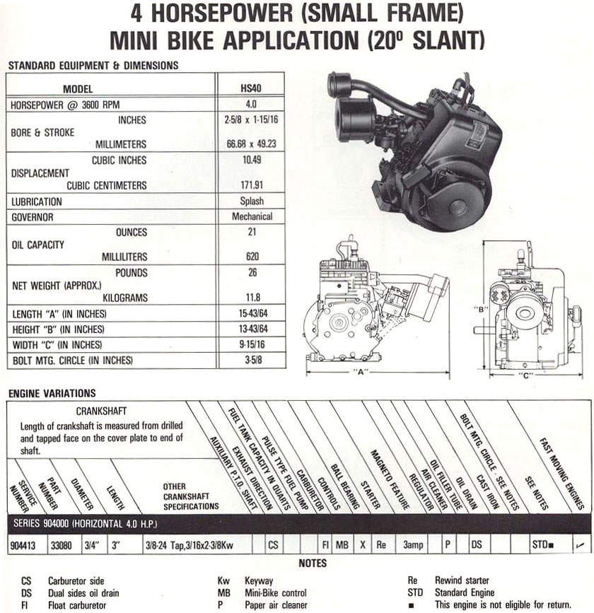
-
With any snow blower motor, there will *not* be a slant intake manifold.
If your minibike application has a 20 degree motor mount, you will have
to deal with this. Ideally, just buy a 20 degree slant intake manifold #33301 (for the HS40).
They are available from BlackWidowMotorSports.net:
Tecumseh HS40
slant intake manifold. Note there are separate slant intake manifolds for the
Tecumseh H35 and H50 motors, which are different (the ports have slightly different shapes.)
Unfortunately BlackWidowMS is the only source for a new slanted intake manifold, and
it's only the #33301 part, designed for the HS40 intake port. But you can use
the #33301 slant intake on the HS50 motor, but you need to take some things
into consideration.
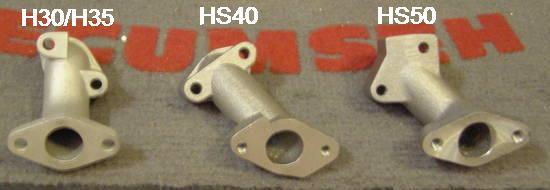
-
The Tecumseh slant intake #33301 is designed
for the HS40 motor. If you're using an HS50, the intake port is not round like the HS40 port, it's a "D" shape.
The #33301 will work, but you need to use a different gasket. Why? Because if you don't,
there will be an opening at the motor/intake mate bottom right, and it will suck in air.
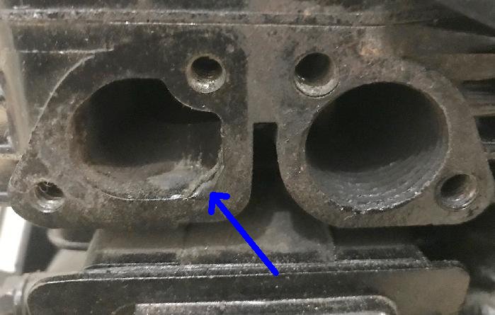
-
There is another approach to fix the HS40/HS50 intake issue. Personally when I re-do an HS50 motor, I put
a small dap of JB Weld on the bottom right corner of the intake port. This way if I need
the motor for a slant application, I can just use the (readily available) BlackWidowMS
HS40 intake #33301 without any issue or special gasket.
That said, BlackWidowMS does offer a special gasket to cover
the differences between HS40 and HS50 intake port. This works too. You just need the
Tecumseh #33670 Exhaust/intake mainifold gasket, and it covers the bottom right "hole",
allowing the HS40 slant intake #33301 to be used on an HS50 engine. Personally though
I like the JB Weld idea... Or heck do both JB Weld and the #33670 gasket!
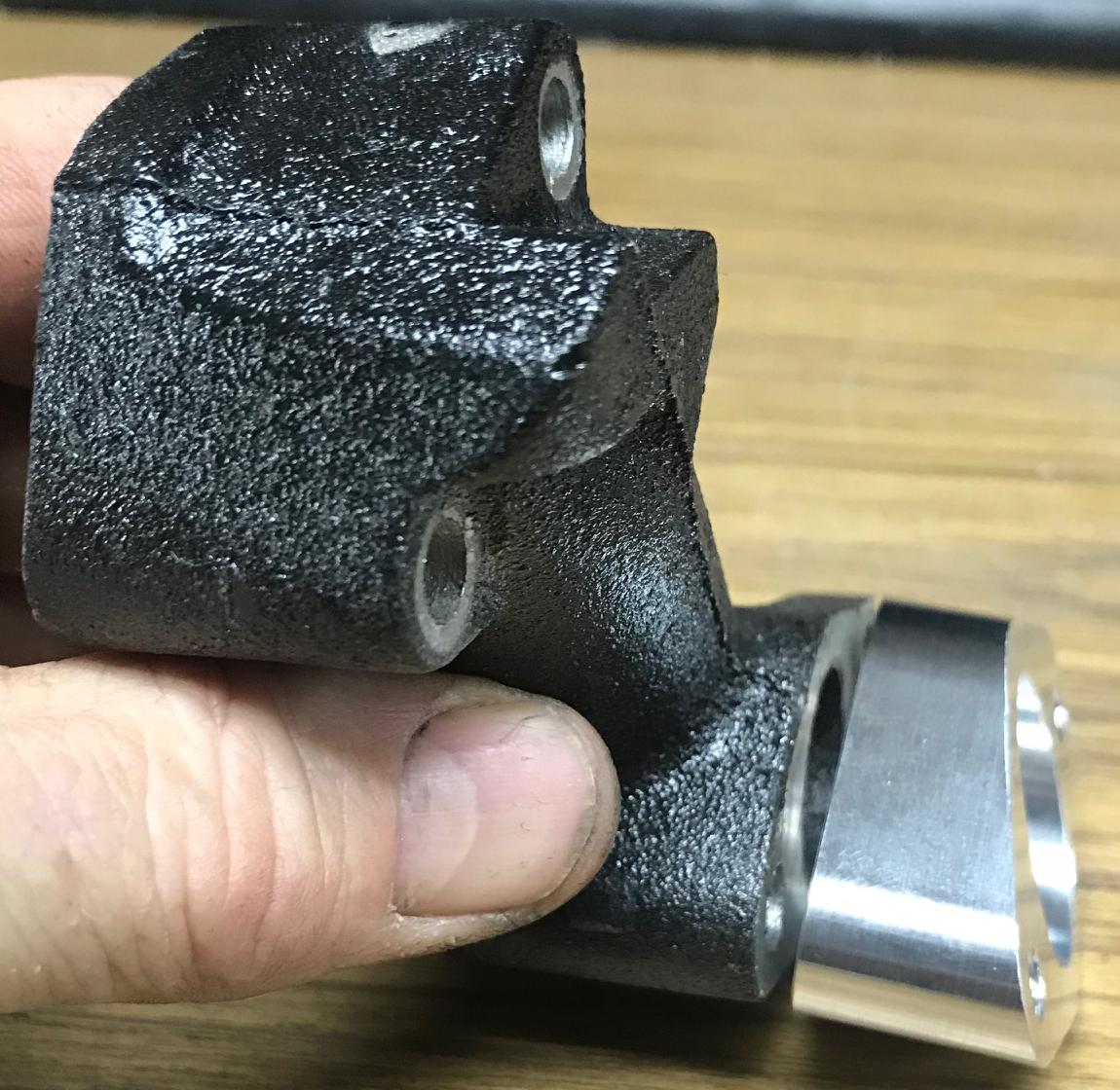
-
Another alternative is something I found on one of the minibike forums
sold by Jamie Nice.
It's an aluminum adaptor that goes between the intake manifold and
the carburetor. This adaptor gives the desired 20 degree slant.
It's a less expensive alternative to the Tecumseh/BlackWidow #33301 slanted
intake manifold, and it works very well. It does require another
gasket though, Tecumseh #33515.
23. Alternative Carbs.
-
One thing I never really liked about Tecumseh carbs
when used on minibikes, is the lack of throttle control and travel.
It's very short travel, pretty much idle or wide open. There is
middle throttle, but it's pretty small on a minibike throttle assembly.
Also I never really liked how the Tecumseh carb hooks up
to the governor. Nor do I like how I have to fiddle with the
high speed adjustment, depending on outside temperature (I live
in a four season climate.)
These things always bothered me. Is there a solution to
these problems? Also can we get a bit more performance out
of the Tecumseh H35, HS40, HS50 motor too?
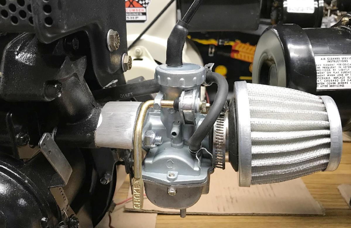
-
I've experimented with several different slide carbs on the Tecumseh
HS40 and HS50 and HSSK50, and have come up with a nice and inexpensive option
for these motors. Did I say inexpensive? Almost cheaper
than a standard Tecumseh carb (if you include the air cleaner assembly
in the formula.) For about $15 to $25 (including shipping) off ebay, you can buy a
a Honda XR75/XR80 Carburetor and air filter. These work great on a Tecumseh.
And they look cool too. There are a couple flavors of this carb. One is
the PZ16 (16mm) slide carb, which works great for a stock HS40/HS50.
If you have a big cam installed the PZ22 (22mm) slide carb works great.
The inexpensive clone Honda XR75/XR80 carbs are really ideal here. The PZ16 is generally jetted perfectly for an otherwise unmodified HS40/HS50. The PZ22, which is an exact clone of the XR75 carb, has a #92 main jet. For a modified HS50 engine with a hot cam and open exhaust, this is perfect. If you go to an XR80 clone PZ22, that has a #95 main jet (as Honda increased the main jet in 1979 with the XR80.) Probably a bit too big, but you get the idea here...
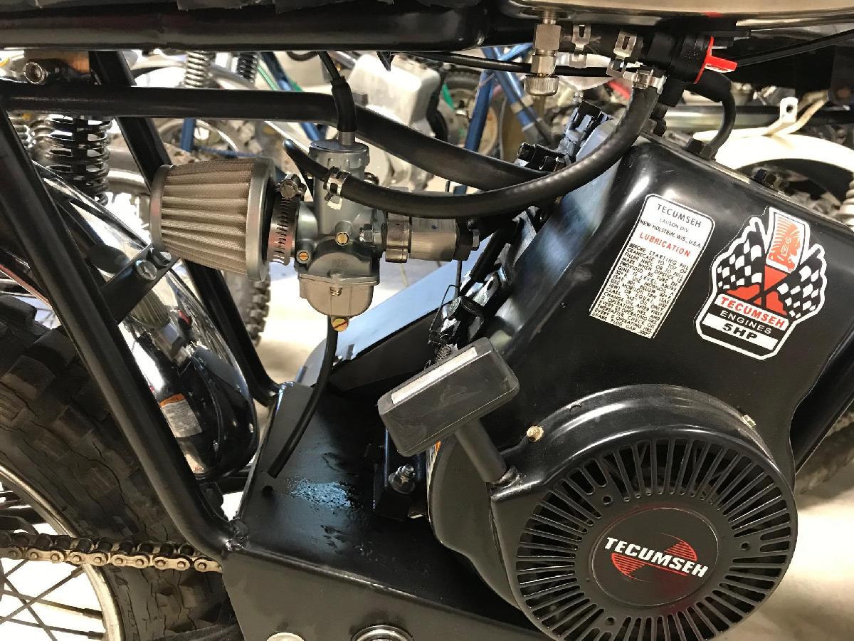
-
I should also mention that you will probably need a new throttle and cable to
work with the slide carb too. But fortunately, that is only about $10 to $15
too. (And your minibike probably needed that anyway.) Personally I used
the DB30 Baja Doodlebug style throttle and cable as sold on ebay. This is
essentially a Honda XR75 throttle copy. It works great with
a slide carb, and is inexpensive. The DB30 throttle assembly comes with
a dual ball cable, which is needed on a slide carb.
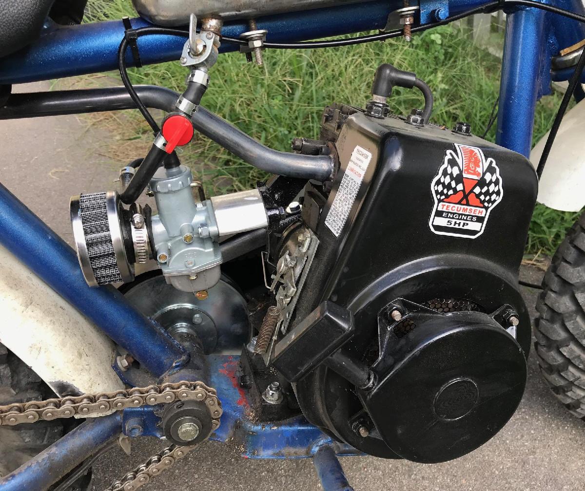
-
The only downside to using the slide carb is that it really needs a
spacer of some sort to move it away from the motor (and more important,
away from the exhaust.) Without the spacer, the throttle cable or
the gas line is a bit close to the motor and/or exhaust. Now if your
application is a slant 20 degree motor mount, the aluminum spacer/angler
mentioned above is an excellent answer to this. Otherwise, you need
to make some spacer from aluminum (which is what I did in the pictures
above.) Is this required? No, but you may find it necessary, depending
on the exhaust your minibike uses.
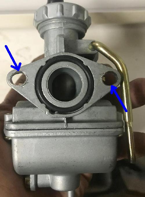
-
Also the 16mm Honda PZ16 clone carb isn't exactly a perfect fit to the existing
Tecumseh intake manifold. It is off by a millimeter or two. That is
easy to deal with though using a drill to make it line up. You have
to make the carb holes a bit wider for it to bolt onto the Tecumseh
intake manifold. Not a hard thing to do. I use a 1/4" drill bit to do this,
moving it at an angle to make the carb mount hole oblong.
But overall I am really happy with the 16mm Honda PZ16 slide carb on the Tecumseh motors. I find it gives a really nice throttle range and a nice performance boast too. They also make this same carb in 20mm and 22mm format. It is basically identical to the 16mm version, except the "throat" is larger. Unfotunately it does not run correctly on the Tecumseh engines out of the box (idles but will not accelerate, unless the choke is on about 3/4 way.) It will need a different main jet to work right. For this reason, if you're going the slide carb route and don't want to mess around with jetting, stay with the 16mm version.
Custom Intake (and Exhaust).
Personally I like making a custom intake for the slide carb. I can get
the float bowl angle just right (important on 20 degree motor mounts),
and can get the slide carb fitted exactly where I want it. To do this you'll
need an intake flange and a carburetor flange. So how do you get those?
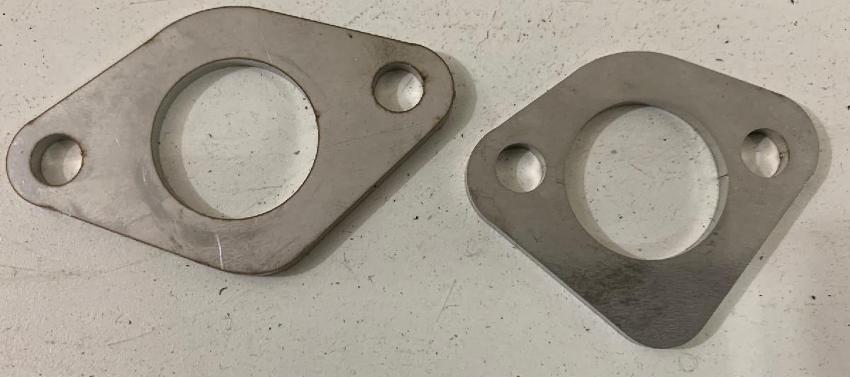
-
I drew up in AutoCad a universal flange design. The carb flange (seen above on the left)
lines up perfectly with the 16mm to 22mm carbs shown in this article. Just buy some 6mm bolts
1/2" long and you're all set, carb bolts right to the new flange. The other
triangle flange lines up really nice with the HS50 intake
port (use black 1/4-20 allen head 1/2" or 5/8" long bolts to mount to the block).
But you can also use this same flange as an exhaust flange too! it's a bit bigger
than needed, but you can use it to make custom exhausts (more on that later.)
Note I've used these flanges on HS40 motors too without issue. The intake port
is smaller on the HS40, but the triangle flange works fine (just a bit oversized.)
In either case, make sure you use stock intake/exhaust gaskets for your motor
to prevents any leaks.
To get these flanges, download the autocad DFX files for the carb intake and carb exhaust/intake. With these you can go to SendCut.com and upload the two DFX files, and they will make the flanges for you on their laser cutter. The minimum order is $29 and that should get you a handful of flanges. When doing this I recommend stainless steel 304 (no rusting) and in .125" or .187" thickness. The .187" thickness is prefered, as when you weld the flange, there's far less chance of heat distortion (but the .125" thick does work.)
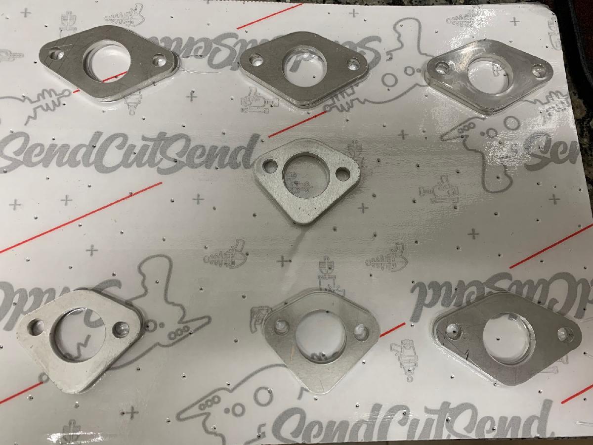
-
Next you'll need some 7/8" tubing. I get stainless 304 steel 5LVL9 six foot long 7/8" thick
wall thickness .065" tubing on ebay (search for 'zoro 5LVL9'). This costs about $40,
and works perfect for both intake and exhaust tubing. With this material
and the flanges you can make several nice intake flanges (and even a custom exhaust.)
Do you need a tubing bender to do this? For the intake, definitely no. But if you want to make custom exhaust, probably (but we'll talk about that later.) You will need some TIG stainless steel welding skills though. For the intake cut the tubing to about 2.5" long. Then you can angle it about 30 degrees in any direction. I tack weld this on the installed motor, and then remove it and do the final welding.
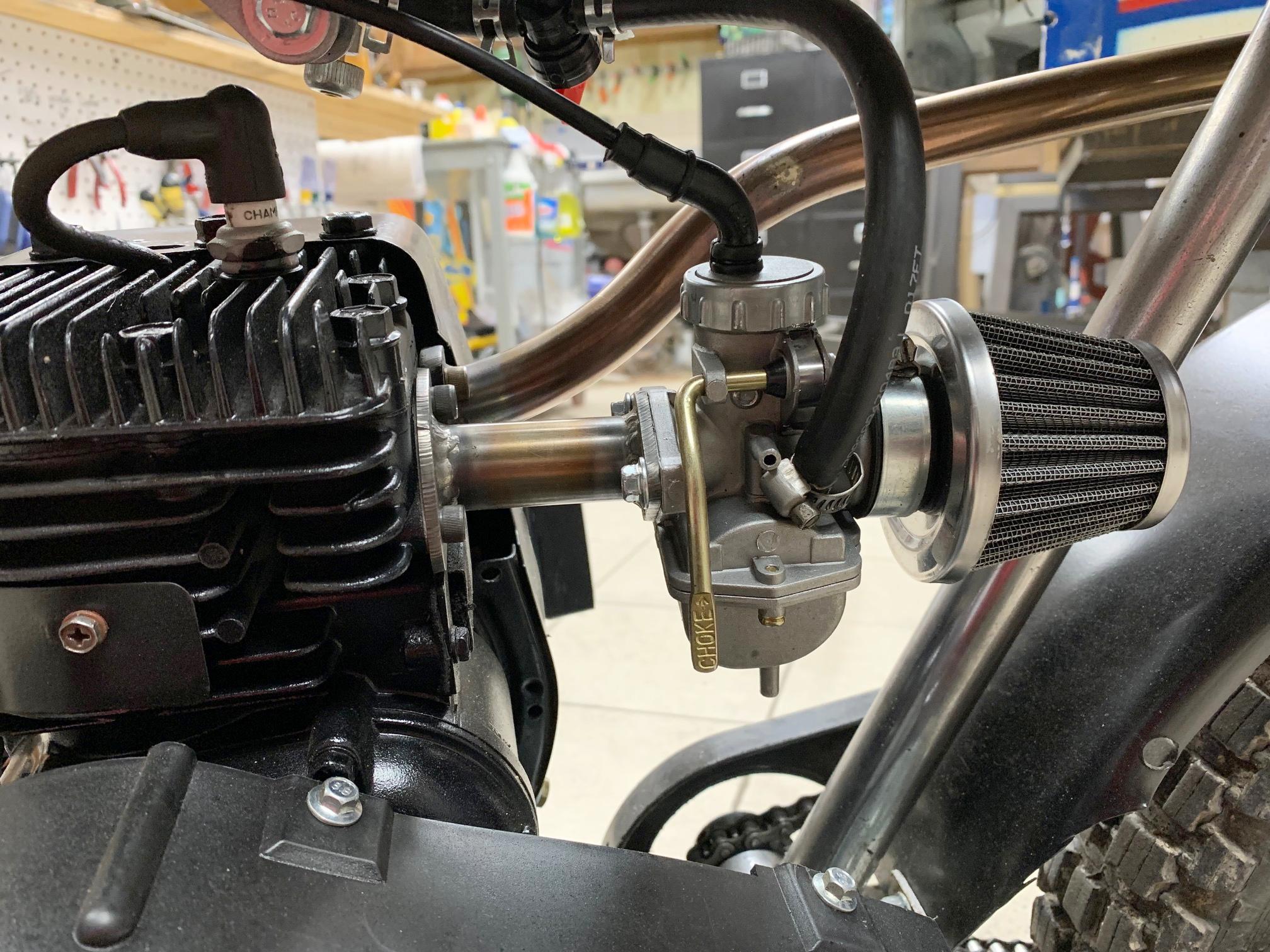
-
Jetting a Slide Carb.
The 16mm PZ16 slide carb seems to have the correct jetting for an unmodified HS40/HS50. The 22mm PZ22 slide carb seems to have the correct jetting (#92 main jet) for an modified hot cam/open exhaust HS40/HS50. But depending on your engine situation, the main jet may need to be changed. I should note that you should try the new slide carb in stock format *before* changing the main jet. Why? Because sometimes the jet is fine. It just depends... These China-made carbs are not consistent. So when I find one that works well, I tend to buy several! Now and then they come with a jet that works great on my motor. Not always, but often...
But changing the main jet isn't a big deal. Yet without the change, often the engine just won't run right. Generally speaking, a main jet of #82, #85, #90, #92, #94 or #95 seems to be the right jet. Things vary from engine to engine and carb to carb. But usually one of those jets will make it run great. I buy a M4 jet pack with variable sizes to get an engine dialed in. Note all these carbs PZ16 to PZ22 (16mm to 22mm) use "M4" style jets. This means the thread size is #4 metric threads. But try the carb as it comes in stock form. If it doesn't run right, a main jet change will be required.
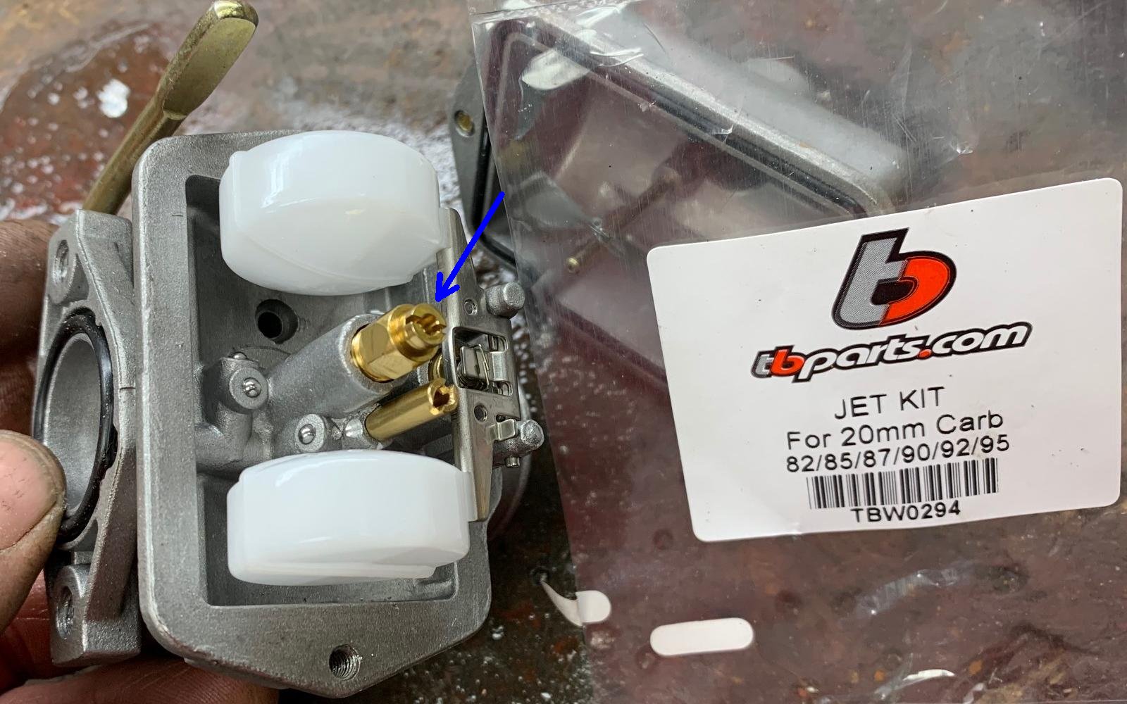
-
Now if you want more performance from a larger carb, the PZ22 carb 22mm
with the metal choke is a good carb. Note there are different versions of
this carb - I do *not* get the one with the round float bowl and right side plastic
choke lever. I like the left side metal choke as pictured above (a copy of the XR75 carb.)
I mean the round float bowl one works fine, but the choke is on the wrong side (at
least for my applications), and is plastic.
If change the PZ carb main jet to #82, #85, #90, #92 or #94 (M4 size), your Tecumseh HS50 will run great and give even more performance if you're using stock HS40/HS50 than the 16mm PZ16 is a great option. The exact jet depends on your motor, carb, and exhaust. For example an open exhaust will warrant a larger main jet. What I have found is the *exhaust* dictates jet size quite a bit. For example, I was running an HS50 with a modified Dyno cam, but used a stock 1971 Rupp Roadster exhaust. Normally the PZ22 would run great with a #92 main jet. But the Rupp muffler made me change the main jet all the way down to #82. So as you see, the exhaust dictates quite a bit when it come to jetting. Likewise a #95 jet is usually too much for an HS50 with a cam and open exhaust... At full throttle the larger jet tries to drown the spark plug with fuel, and it will sputtle or backfires when you let off the throttle. I've found the stock XR75 main jet #92 to work best here.
Also note that they sell these carb in 19mm and 20mm styles too (with the metal choke lever). From what I have found, these work fine, but again, will need a main jet change. A #82 to #95 jet will work in these carbs too.
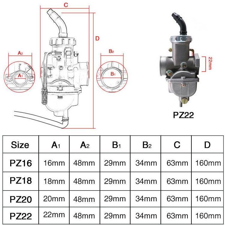
-
So why use a 22mm carb over a 16mm carb? Well if you go to a performance cam,
the 16mm carb isn't big enough to support it at high rpm. Therefore the 22mm carb is just
more versatile, in case you decide to install a performance cam. But if you are
using a stock cam, the 16mm PZ16 carb "out of the box" (generally) works better, and you don't
have to re-jet it (though depending on which 22mm carb you get, sometimes out of the
box they are jetted correctly too.) Frankly if you look at the specs above, you can
see there isn't a lot of difference in the sizes between 22mm and 16mm (just the throat
opening.) Hence it's not a huge difference.
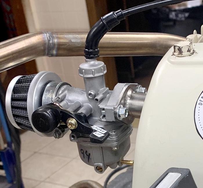
The above Tecumseh H35 motor.
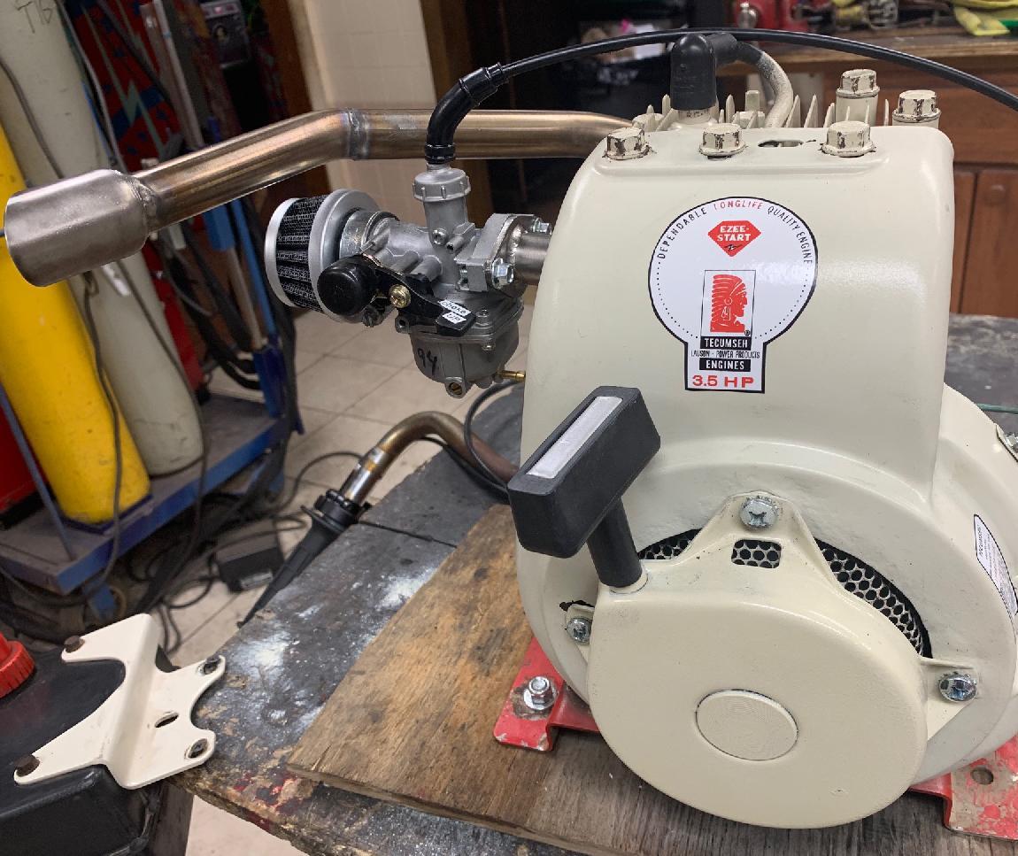
Note the round float bowl slide carbs also do work. I just don't personally like the plastic choke assembly. But on some mini bikes, you may need this, because the choke is on the right side. I have used the 19mm version of this carb on a Tecumseh H35 (side popper), and the right side choke was needed (because the exhaust is on the left side!) It works fine, but again, you need to change the main jet. The stock jet on the round float bowl PZ19 carbs is a #73, which is just too small. On the H35 motor (with open exhaust) I found, again, a #90, #92 or #94 main jet M4 size to work great.
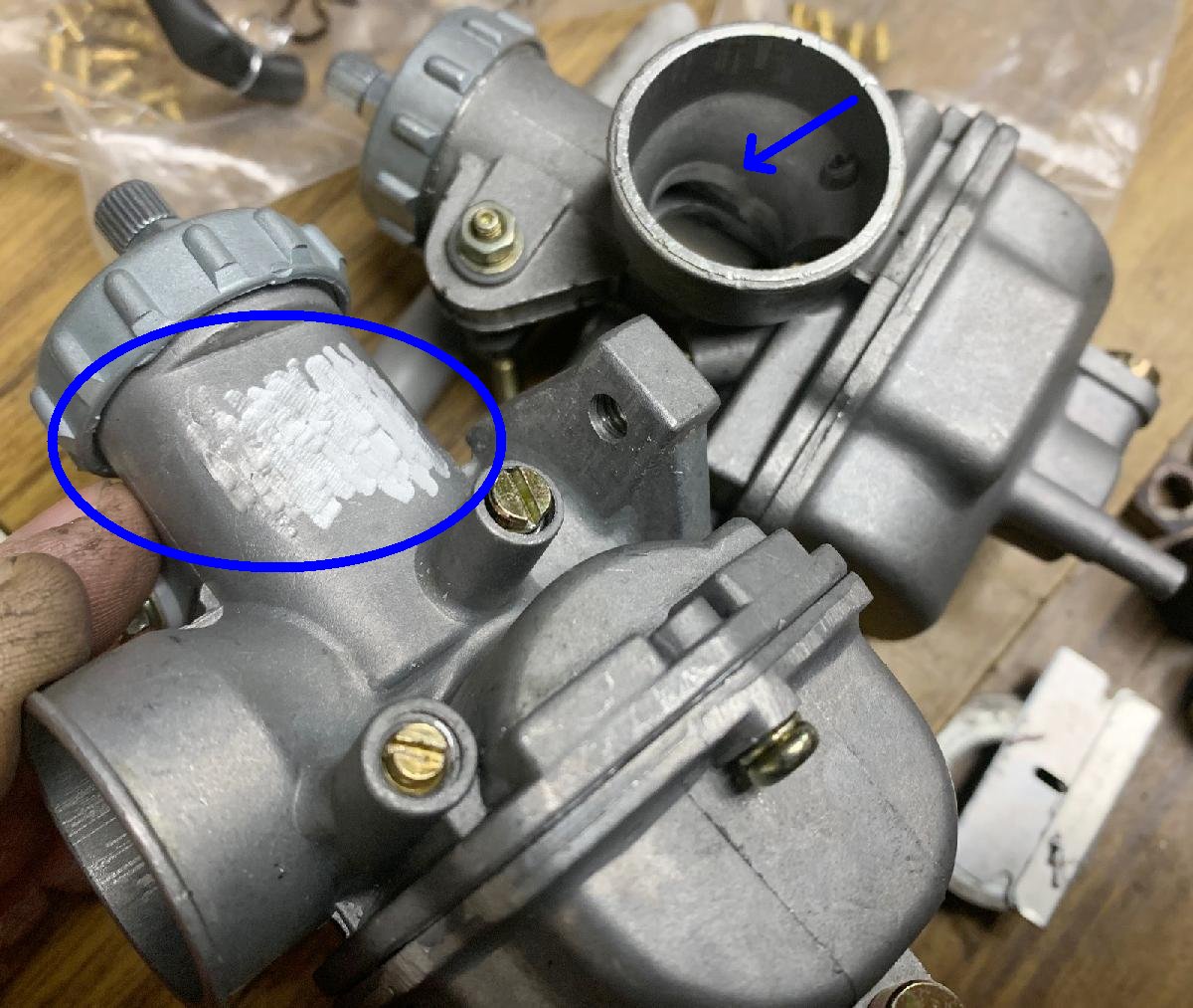
If you buy your carb on ebay, just be aware there are differences. I've usually buy four carbs at a time, and I notice every few months, the carbs seem to change a bit. The last batch of 22mm carbs I received had the side of the carb ground off. Like it said something that they didn't want the end user to know! Also the inside of the carb was ground open. My thinking was this was a smaller (19mm?) carb that had the throat opened with a die grinder. I tried this carb and found it to work OK, but my usual choice of jetting did not work. The stock jet (which was visually small) worked best. In 16mm carbs I like the brand "Keihin" and "Xibuwang". But unfortunately the brands seem to change a lot on ebay. I'm not sure why this is, but maybe the dies wear out? This may be why jetting isn't "firm" at any particular size, because the carbs vary so much.
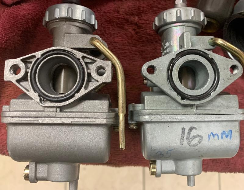
Personally I use the DB30 throttle/cable assembly for these slide carbs. These are readily available on ebay for about $15, and are XR75 throttle copies. Generally the cable is the correct length for PZ16 to PZ22 carbs. But sometimes it's just a little too short. In this case, I remove the stock entrance metal (by bending the flared ends) and discard it. Then purchase a 6mm alloy bicycle cable adjuster on ebay. This fits perfectly into the top of the PZ cable entrance, and basically lengths the DB30 throttle cable (assuming you needed that.) It also gives some adjustment. It will require you to drill out the cable hole with a 1/8" bit though, so the throttle cable end will fit through the adjuster. Be sure to re-use the rubber dust boot off the old throttle entrance metal.
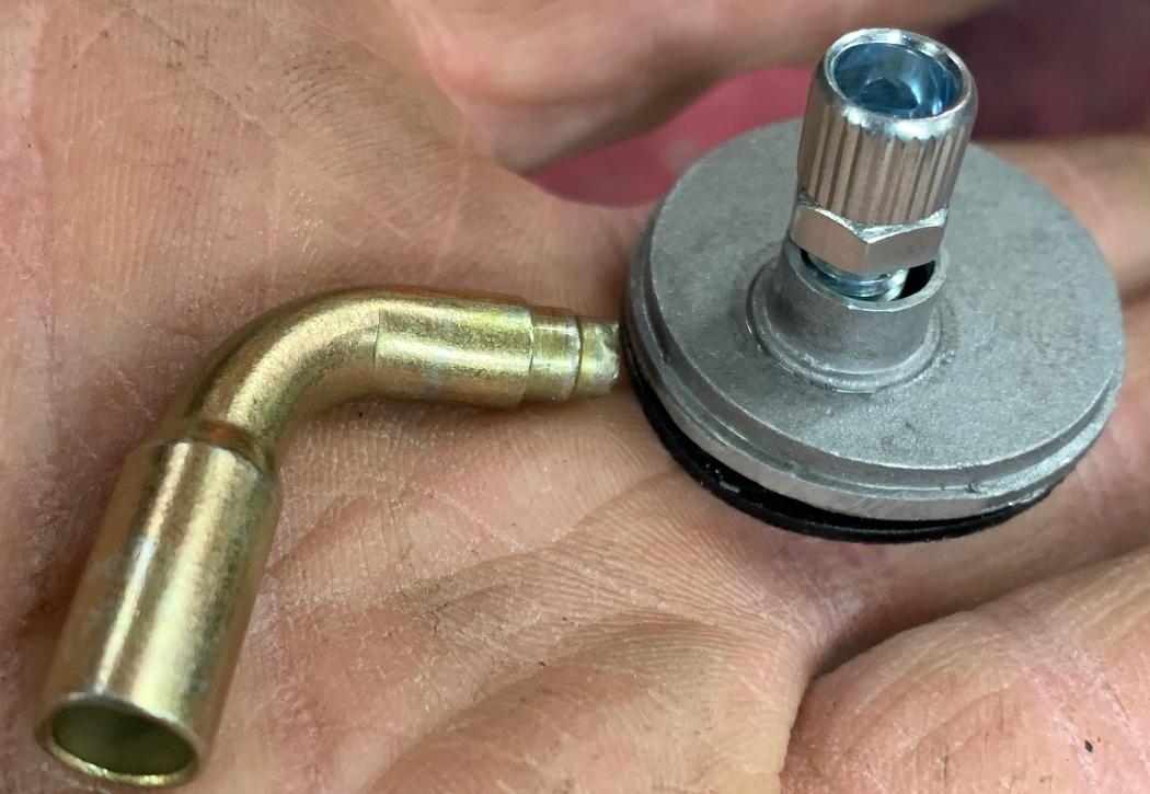
Also I should mention on the PZ carbs there are two adjustment screws. One is for the idle - it just moves the slide up and down to increase or decrease the idle speed (by moving the slide position.) The other screw is the idle air intake adjustment, or low speed circuit. On this screw, I have found it needs to be in all the way, and then backed out about 1/2 turn to 1 turn. That seems to make the PZ16 or PZ22 work best.
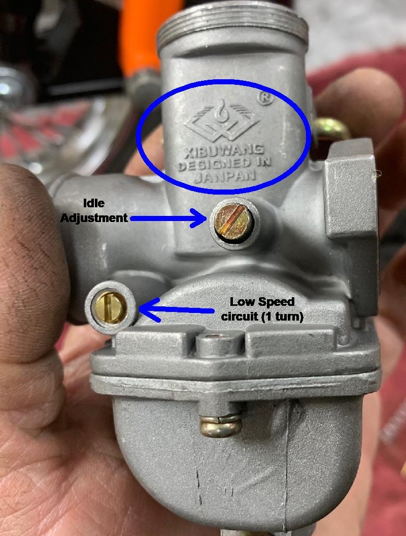
I have also experimented with a slide carb on the Tecumseh AH817mb two cycle engine. Though this document concentrates on the four cycle HS Tecumseh motors, there were some minibikes (Fox and MTD) that came with a two stroke Tecumseh AH817mb engine. This motor was supposed to be 5 horsepower but in two stroke format. Parts are near impossible to find for this engine, so my suggestion is to avoid mini bikes with it. But if you do come up with one, and it runs, a PZ19 carb with stock jetting (needle on the slide raised one notch to make it richer) worked great. This replaces the stock Tecumseh diaphragm carb that has a really small diameter throat. A custom intake manifold will be needed for the PZ19 carb. Also it is ideal to keep the new intake manifold as short as possible. Condensation can accumulate on the manifold when running otherwise. Run at 32:1 gas/oil mixture.
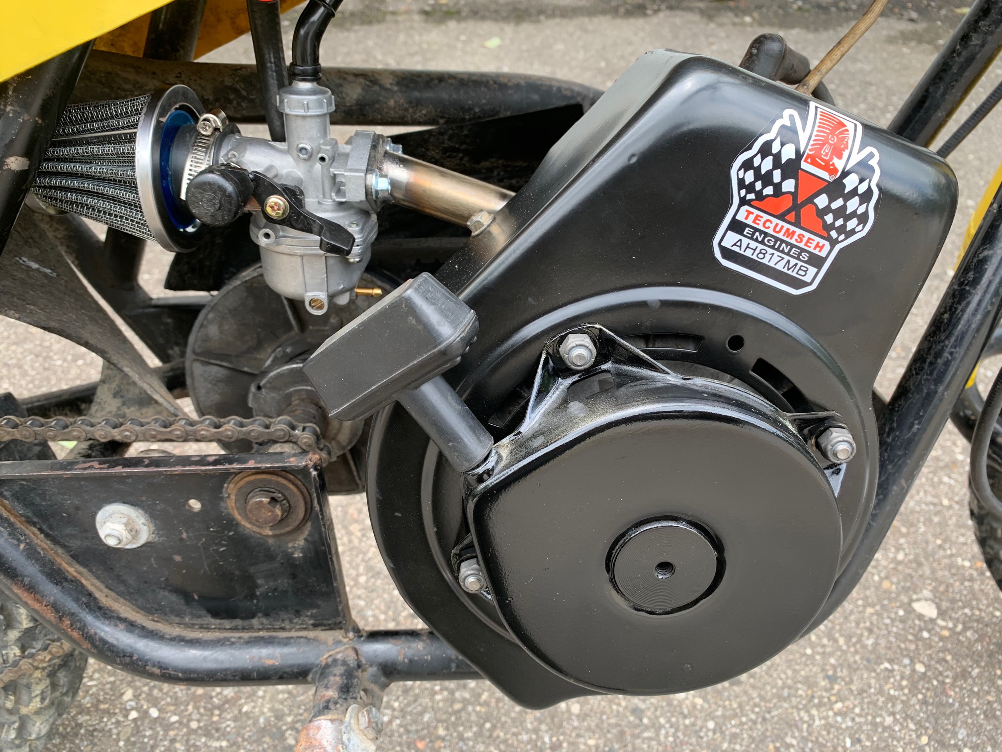
Carb Jets.
If you're using a PZ16 (16mm) carb, generally speaking it is already jetted well
for the Tecumseh HS40 or HS50 with a stock cam and stock exhaust.
But if you're going for more fuel (that is
you have a big cam/open exhaust and you're running high RPMs), a PZ22 (22mm) carb is in order.
But you have to re-jet this carb. What determines jetting? A bigger cam will
have some impact (not a ton, but a bit). The big thing is the exhaust.
If you have an open exhaust, the main jet number will go up.
For example on an HS50 engine with a PZ22 carb and a dynocam 245 and open exhaust, I typically run a #92 or #94 main jet. An HS50 with stock cam and the PZ22 carb and open exhaust, it gets a #90, #92 or #94 main jet. But here it gets interesting... I have an HS50 with a dynocam 245 and PZ22 carb, but a Rupp Roadster muffler (with a spark arrestor.) The Rupp Roadster exhaust is a nice exhaust (much more quiet than an open exhaust), but it's a fairly large pipe and fairly straight. It has a "Harley" type end, so it looks cool too, and is easy to adapt to most minibikes. But it is restrictive because it's an actual muffler with a spark arrestor. In this case the main jet went down to a #82. That's quite a big difference of jet sizes, compared to an open exhaust.
When testing jet sizes, if the motor runs nice at 3/4 throttle, but then at full throttle cuts in and out (kind of like someone was pressing the kill switch for just a moment), this means your main jet is too big (too rich). What is happening is too much fuel is drowning the spark plug. Also sometimes you can just tell when you hit full throttle that the engine seems to struggle a bit. Again perhaps the main jet is too big. Go down a size or two in main jet size. Another thing to try is moving the needle down, which will make the motor run more lean. Personally I have not found a big difference in moving the needle position, so I leave it in the stock middle slot, and play with main jet size.
When running your motor to test jet size, you need to do this under load. That is, mounted in the minibike and riding it (and at a temperature/altitude that is 'normal' for you). You can't really test jet size any other way. Should you get some backfires when you let off full throttle? From my experience, yes. If you have no backfires, I have found the main jet is usually too small. You will get some backfires even with the correct jet. Not excessive backfires, but some.
Another thing to do is to check the spark plug. Go full throttle for a few seconds and then hit the kill switch. Remove the spark plug and check the color. If black you're too rich. If white you're too lean. A nice grayish white color should be seen.
Jetting Alternatives.
Sometimes you will have to re-jet the slide carb. You can buy jets, or
there is another way to re-jet a carb. In the case of the PZ22 carb,
we want a #92 jet (which is the stock XR75 jet size.) You can drill the original jet (which seems to be a #75)
to the larger jet. All you need is a #64 drill bit (and a drill that will
chuck a bit that small.) Just drill straight down the original jet that
came with the PZ22, and you'll have a #92 or #94 jet. By the way, the jet numbers
are metric sizes. That is a #92 jet means the jet hole is .92mm in diameter.
The SAE (American) size equivalent is a #64 drill bit. If you want to
go as a #94 jet, use a #63 drill bit which is pretty much exactly .094mm
(aka a #94 jet). The problem is, it's hard to drill without any wobble.
So using a #64 bit probably get you more like a #94 jet.
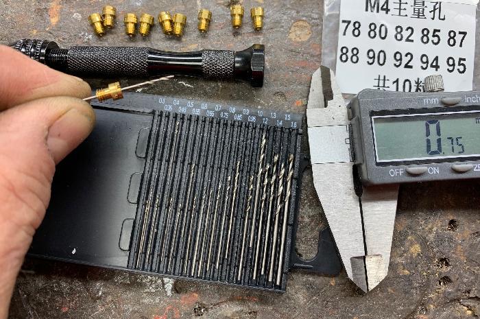
To be honest though, drilling a jet really does not work all that well (unless you're in a pinch.) It's way better to just buy the proper jet. You can go to ebay and buy an assortment pack of jets M4 jets for like $10. I highly suggest this over trying to drill a jet.
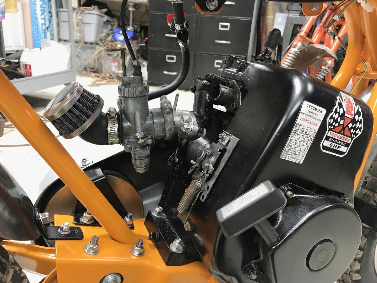
-
Dell'Orto Carbs.
Dellorto carbs also work nicely on Tecumseh motors. These are Italian made carbs, from a company that's been around since 1933. The Dellorto Ua19s is probably the most famous of the Dellorto carb types. This was used as a standard carborator on the 1971 Rupp Black Widow. It was also an option for the Roadster and Hustler. It did not come with an air filter (!), which is really strange. As it would take about one hour of dusty riding to ruin the engine. Instead there was a "velocity stack" or trumpet for air intake. Not a good idea, but that's how they installed them on the Black Widow. I have found that using a women's sock or a short panty hose on the megaphone air intake works as a cheap air filter (use a 1 1/4" pinball rubber to secure it.)
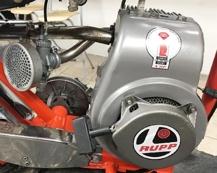
-
Other Dellortos work really well on HS50 motors too,
if you have the correct intake manifold (they are available for HS40 and HS50 engines from
www.BlackWidowMotorsports.net).
The BlackWidow intake manifolds will work for 16-19mm Dellorto carbs.
I've used UA16s, UA18s, UA19s and UB22 Dellorto carbs on HS50 motors, and they all give very nice
performance increase over a stock carb. Is there any difference in the 16mm or 18mm versus 19mm carbs?
Not that I can tell, they all work pretty well (assuming you have the jetting correct.)
In fact, I find the Dellorto carbs to be really nice on the HS40 and HS50 engines.
The 1968-1969 Rupp catalog shows the Dellorto UB22 carb available as an
option for the large frame H50 motor mini bikes. Likewise the Dellorto UA19s was
an option for Rupp Roadster bikes from 1971 to 1975. Pretty cool option for
those bikes.
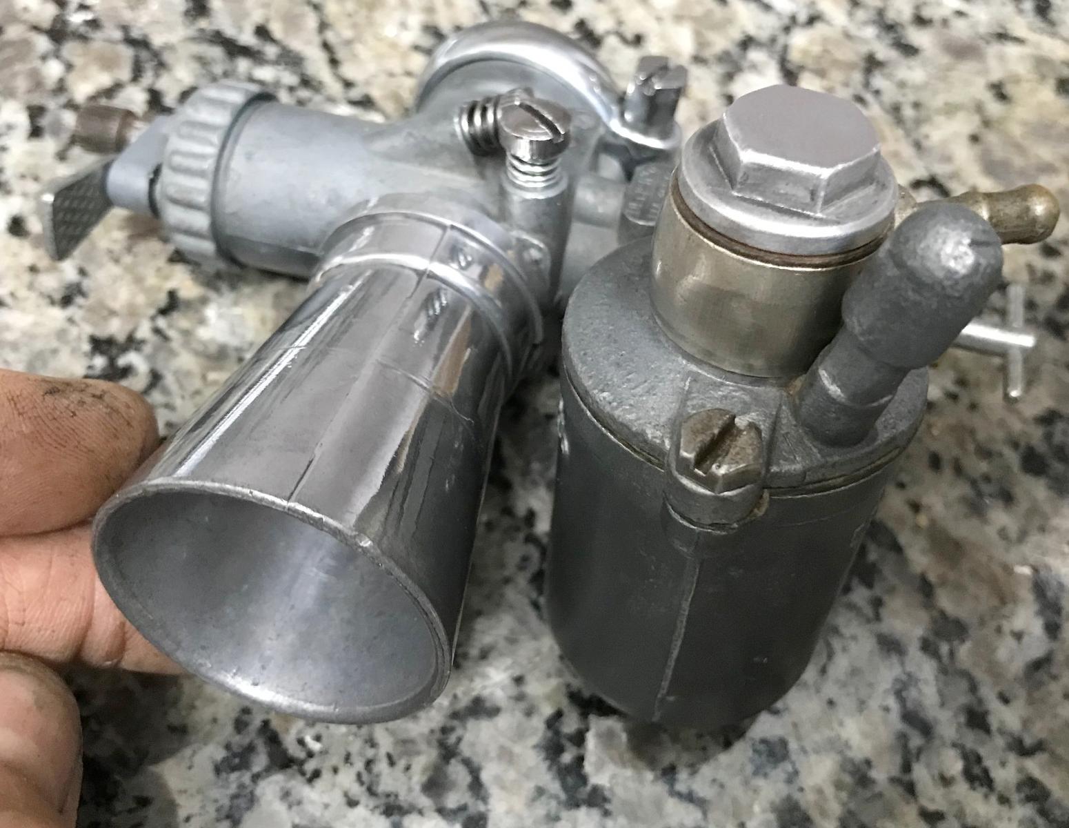
-
For reference, Dellorto used a lot of abbreviations in their model numbers.
The number itself is the MM size of the carb. But here's some of the abbreviations:
- U - Carb type, first letter, removable float bowl.
- M - Carb type, first letter, fixed float bowl (not removable).
- A - Generally clamp type fitting.
- B - Generally rubber sleeve "elastic" type fitting.
- F - Fixed mount (UBF22 for example).
- S - "Sinistra" or "left" in Italian. Left hand idle mixture and idle speed screws.
- D - "Destra" or "right" in Italian. Right hand idle mixture and idle speed screws.
Using this info, the UA19s is "U" for removable float bowl, "A" for clamp fitting, 19mm (size toward engine), "S" for left side idle adjustment. Some other suffix letters may have no specific meaning, they have certain original applications.
Generally speaking, the UA and UB Dellorto carbs are great for Tecumseh engines. But the MA Dellorto carbs also work well. On the UA/UB Dellorto carbs though you have to make sure the float bowl angle is workable. They come everything from level to 12 to 30 degrees. For a tecumseh engine, 12 degrees is probably OK, but you really want a level float bowl. The really angled float bowls won't work (anything above 12 degrees.) Note the UA19s has a level float bowl (as a comparision.)
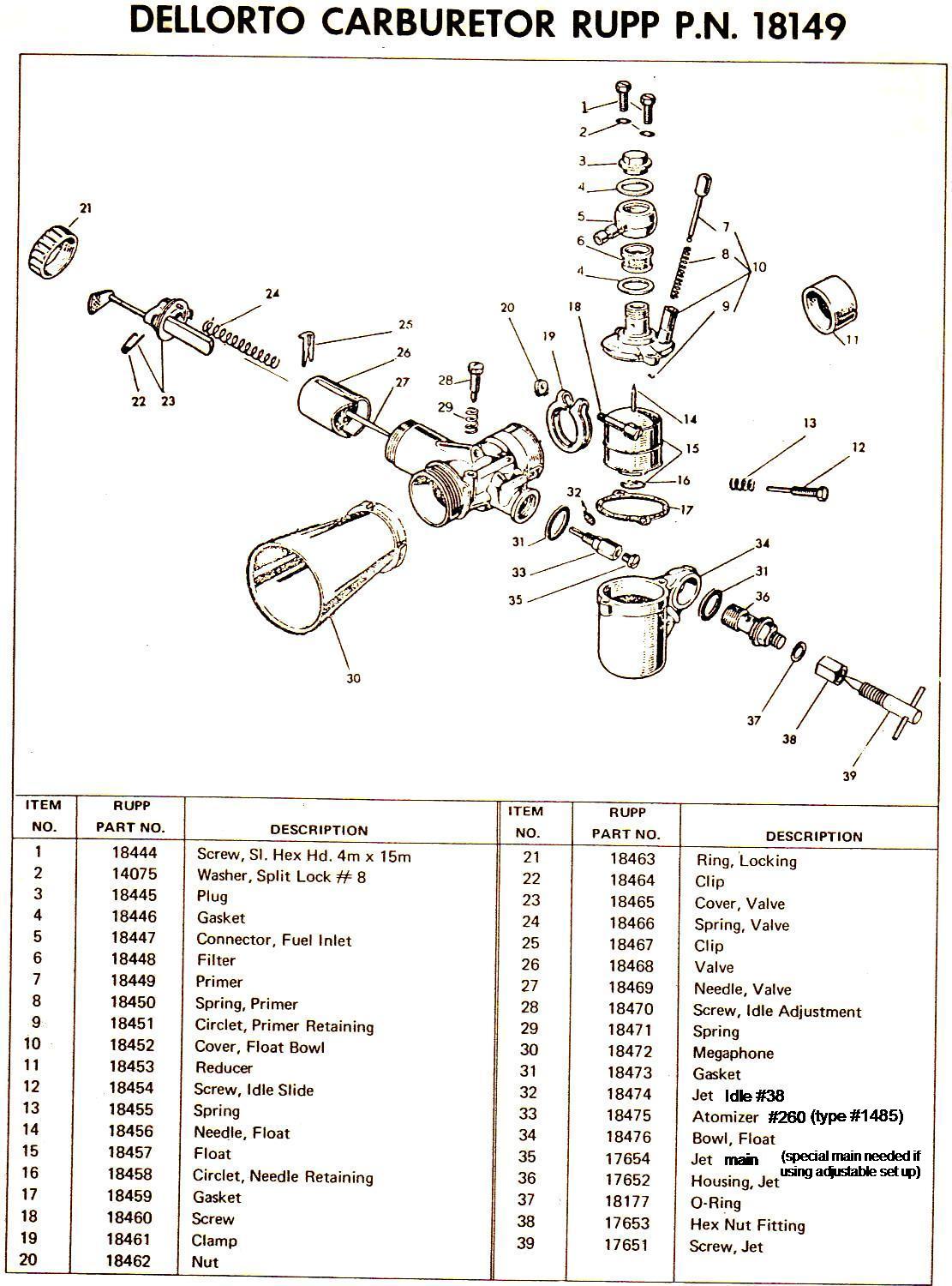
-
Note there was a high speed adjustment jet screw
on the Rupp installed Ua19s carbs. If this is missing (most Dellorto carbs don't have this,
but use a standard "banjo" bolt instead to hold the float bowl in place),
it's expensive to get the parts to install it. It's not a required thing
if you're jetting is correct. But people look for it if the carb is
going on say a Rupp Black Widow. Here's the parts needed, available from
www.BlackWidowMotorSports.net:
- #17651 Hi Speed jet screw, UA type (part #39 above) $10.00
- #17652 HiSpeed Jet Housing, UA type (part #36 above) $40.00
- #17653 Hex nut for HiSpeed jet housing, UA type (part #38 above) $2.50
- #18177 O-Ring for HiSpeed Jet housing, UA type (part #37 above) $1.00
- #18473 0-Ring for HiSpeed Jet housing, UA type (part #31 above): $1.00
- #17654 Main Jet for ajustable set up (fits in atomizer, part #35 above) $15.00 REQUIRED
- #18475 Needle Jet (type 1485) Atomizer #260, UA/UB type (part #33 above) $26.00 (probably not needed)
- #18474 Pilot Jet #38, UA/UB/MA/MB type (part #32 above) $12.00 (probably not needed)
Total cost for conversion is $79.50 ($54.50 plus $15 for the main jet receiver, which is *only* available from BlackWidowMotorSports.net and is required to work with the high speed jet.) A rather expensive conversion. There is another source for the adjustment UA/UB Dellorto main jet at www.guzzino.com/deubadmaje20.html, but you still need the $15 main jet receiver #17654. Don't forget with the above adjustable receiver jet. You also need a #260 needle jet and a #38 pilot jet (which your Dellorto should already have, so you probably don't need to buy those.) Other Dellorto parts are available at www.guzzino.com/deub202224.html
On the adjustable high speed jet... This can be added to any Dellorto carb from UA 14 to 19mm and UB 20 to 24mm. But you do need the high speed jet receiver ($15), which is only available from BlackWidowMotorSports.net. You can not use the adjustable jet with a standard Dellorto main jet - you have to use the special high speed main jet receiver (which is a straight hole 3/32" or #41 bit .096" in diameter.) You can however made this jet receiver. I've done it before in a pinch. Get a 1/4-20 brass bolt about 1" long, and center drill it with a 3/32" or #41 drill bit. Then grind off the threads, and run a 5mm .80 thread die down the shaft. Then cut the length to be 1/2" in total length. It's kind of a lot of work, but if you're in a pinch, it does work (it's a lot easier to just buy the $15 jet receiver from Black Widow though.) Note you can't take a standard jet and just drill it with a 3/32" drill bit - the head of the receiver main jet has to be higher than a standard Dellorto main jet. Now if you could make the head taller, maybe that would work...
When adjusting the high speed jet, I found that it is generally just a 1/4 to 1/2 turn out from, "all the way in". A little turn does a lot on the adjustment. But start with a 1/2 turn out and dial it in from there.
Dellorto special high speed jet (left) versus a #75 standard 5mm Dellorto jet (right).
Notice the difference... you can't use an adjustable high speed jet with a standard
5mm Dellorto jet. You must have the special receiver jet, which has a 3/32" straight hole
drilled through it (and it's taller in profile.) The adjustable main jet receiver is
a straight hole. Opposed to a standard Dellorto main jet, which has a conical shape to the hole.
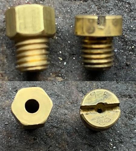
- UA16s. Usually comes with pilot jet 45, needle jet (type 1485) 260, 5mm main jet 80. In this format runs great on a stock HS50. Really nice, good power band.
- UA18s. Usually comes with pilot jet 38, needle jet (type 1485) 260, 5mm main jet 82. In this format sputtered. Changed to pilot 40 and main jet 85, now works great. This is an awesome carb on a HS40 or HS50 motor.
- UA19s. I've bought a number of these and they are all over the place with jetting. Really needs to be pilot jet 38, needle jet (type 1485) 260, 5mm main jet 98 or 100. In this format it runs great on a HS50 motors. The high speed adjuster is helpful to have too, lets you dial in the carb nicely. But a special high speed jet receiver (which fits into the atomizer needle jet) is required. Note the adjustable receiver jet is basically a regular jet drill with a #41 (.096") drill bit. If you don't have an adjustable high speed, a #98 or #100 main jet should work fine instead.
- UB22bs. This is a pretty large carb for an HS50 engine, but it does work. Usual jetting that I've seen is pilot jet 45, needle jet (type 1485) 260, 5mm main jet 95.
Dellorto Jetting.
Here's a rundown on the Dellorto carbs I've tried on HS40 and HS50 motors.
Jetting is important on these. Remember the pilot jet controls the idle.
The needle jet (atomizer) is what the needle moves in and out of,
and controls 15% to 60% percent of throttle. The main jet screws into the
needle jet and controls 50% to 100% of the power range.
Note that Dellorto also had different float bowl weights available. On the UA19s the weight is 7.5 grams. But I've used 6.5 grams with no problem. I'm not sure the float weight is that big of a factor.
24. Drilling the PTO.
-
If your Tecumseh motor is older, there's a good chance it is
not drilled for a bolt at the end of the PTO. Why do you need the bolt?
Well we don't use set screws to hold clutches any more! (They
just loosen, fall out, and your clutch flys off.) The set screw
idea went away with the 1980s. Now we use a 5/16-24 or 3/8-24
bolt at the end of the PTO to hold the clutch in place. In fact,
if you're using a torque converter, that's the only way you can
run.
So how do we deal with a non-drilled PTO? Well it's a lot easier than you may think. It's a cast steel material, and it's actually pretty easy to drill with a standard bit and hand drill. The only problem is, how do you drill it centered?
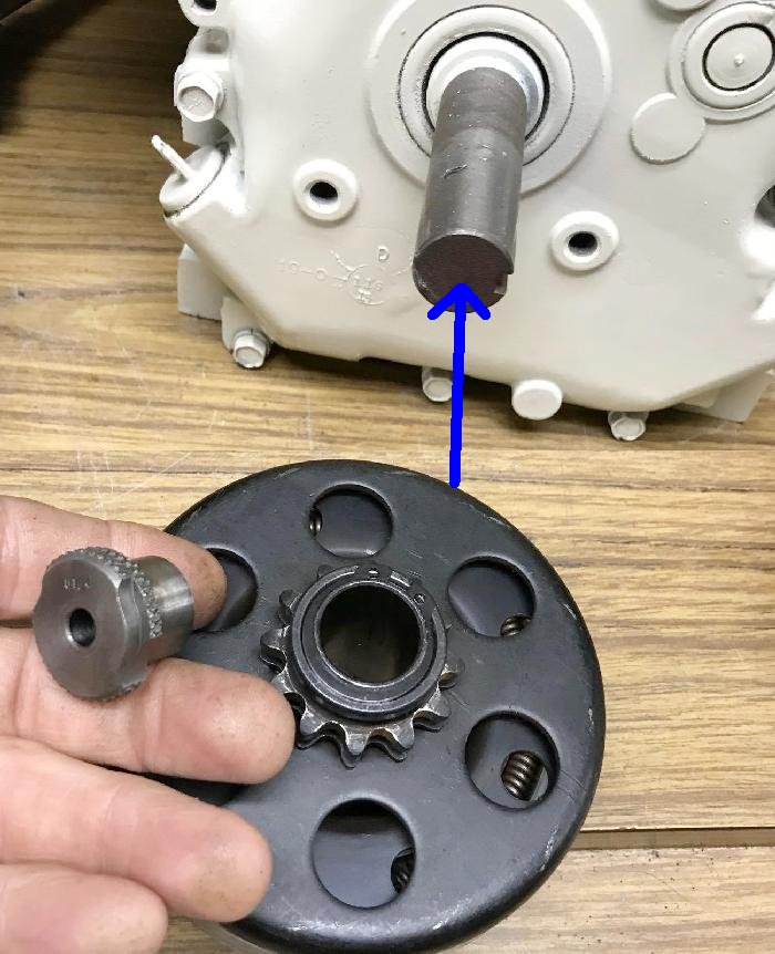
-
To do the job you'll need an old centrifical clutch and a 1/4" drill bushing.
The drill bushing is availiable from
McMaster Carr,
part #8493a074 (drill bushing 3/4" OD and 1/4" ID). With the
drill bushing installed in the clutch, and the clutch installed
on the PTO, it's an easy job to use a 1/4" drill bit and drill
into the PTO shaft about 3/4 of an inch.

-
After the 1/4" hole is drilled into the PTO shaft, remove the
drill bushing and clutch. Now re-drill the hole with a letter
bit "I" or 17/64" or even a 9/32" drill bit.
Then run a 5/16-24 tap into the hole. Remember
to use oil on the tap. Go in a full turn, then back a 1/2 turn (this
helps clear the flutes.)
Do this until your tap does the 3/4" hole depth (or close to 3/4".)
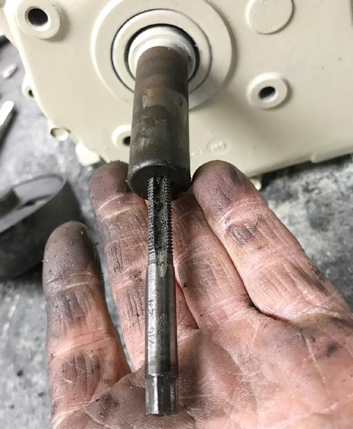
-
Note we are using the "fine thread" 5/16-24 version of the 5/16 bolt.
This is important. Do not use the more common 5/16-18 tap/bolt.
Fine threads are required for this application.
25. What about the Exhaust?
-
Snowblowers generally come with a usable but not optimal
exhaust, the Tecumseh #35771 or #32648 or #33697
muffler and gasket #35865. There's also another exhaust
that is a bit more minibike-ish, Tecumseh #37684 which
has an extended pipe.
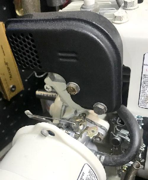
-
Really the 'standard' minibike exhaust was the
Taylor Products model 100 (Tecumseh parts #33222, 33223, 33224),
but they are no longer available (NLA). Taylor went out of business long
ago, but sometimes you see them on ebay. Note there are
several different Taylor styles (bends) and exhaust port
styles. So if you're going that route, make sure you
get the 'right' Taylor with the correct bend and correct
exhaust flange (HS40 and HS50 have slightly different
exhaust ports, as does the H30/H35.) But be prepared to pay for this exhaust.
Frankly I don't think they are worth the price.
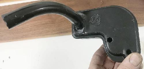
-
Personally the path of least resistance is to just use
the Tecumseh 35771 which was stock on most snowblowers.
I take the exhaust to a wire wheel to knock off all the
loose particles and rust, and then paint it with a high temperature
black paint (rattle can). Short of buying a new 35771 exhaust (they are actually
pretty cheap), this makes the original exhaust look somewhat
decent. Alternatively you can look for the Taylor Products minibike
muffler on ebay, but it won't be cheap. If you have a tubing
bender you can buy 7/8" tubing and bend your own exhaust
(flanges are available on ebay.) But most people don't have that
capability.
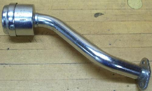
-
We could re-make the Taylor Products model 100, but the
issue is all the different motor configurations. The HS40 and HS50
have slightly different exhaust ports. Angled motor changes things too. And then you have the
H30/H35 variants too. It would be a fair amount of work, for
a pretty limited market. Hence I haven't seen anyone re-issue these.
You could also make your own using the Tecumseh #730165 exhaust adapter kit
and some pipe.
Now if you are making a performance Tecumseh, you will need an open exhaust. Don't even think about putting in a performance cam and slide carb, without some sort of straight open exhaust! A standard mini bike muffler, any muffler, will restrict the set up, and performance will be held back.
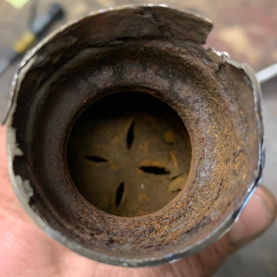
I removed the restriction plate to see if the Rupp Roadster2 exhaust
could be "opened up". But to my surprise, the big 2" pipe restricts down
to about 1/2" wide! No wonder this exhaust is so quiet, it's way too
restrictive for any performance.
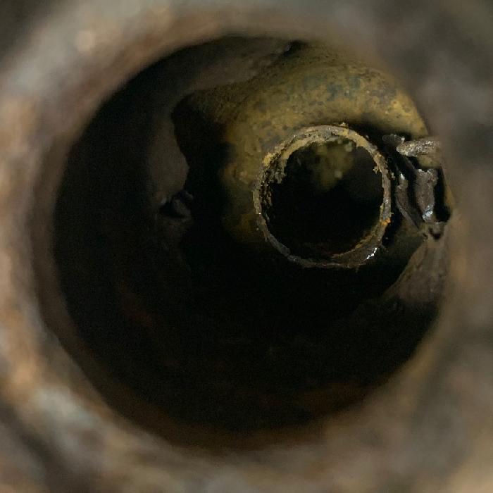
-
The most adaptive and readily available exhaust is probably the 1971-1975 Rupp exhausts. The 1971-1975 Rupp Roadster2,
Hustler, Enduro exhaust is a really great exhaust. I mean it looks big and
manly, and it exits the back of the bike in a nice place. I've used this exhaust
on many minibikes, as it's pretty cheap and available used. But don't be fooled!
This exhaust will suck the life out of a performance engine. I cut opened one
of these to see if I could neuter the muffler... short story, you can't! And
it showed me just how restrictive this pipe really was.
The only other good "fancy" exhaust is the 1971 Rupp Blackwidow exhaust. It's a 7/8" straight chrome pipe, and is available brand new from BlackwidowMotorsports.net. Robertson also makes their Torque Pipes which is a good option. The only other choice for more performance is to buy some 7/8" stainless steel 304 tubing 5LVL9 with .065" wall thickness, and bend/weld your own exhaust. This is what I like to do. Also this tubing works nicely for making your own intake manifold.
Making Your Own Exhaust.
This is the prefered method for me. If you have a tubing bender, and a TIG welder,
you can make a pretty nice custom open exhaust. First you need some 7/8" stainless
steel 304 tubing with .065" wall thickness. I buy 6 foot lengths from Zoro (direct or on ebay)
product 5LVL9 (same tubing used for the custom intake manifold, mentioned above.)
You will also need a flange. I use the same flange used for the intake manifold, as explained above (using the
DFX file and
SendCutSend.com to have it made out of .125" thick stainless steel.)
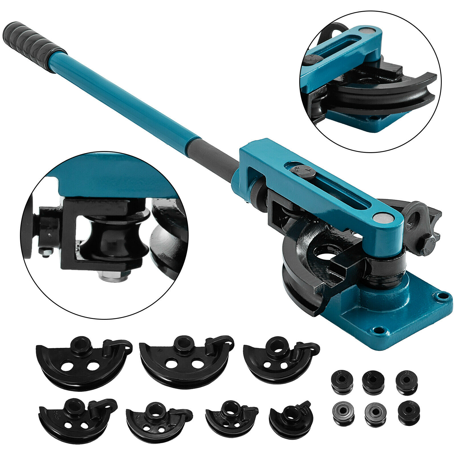
-
Lastly, for a nice "Harley" style end to the custom exhaust, use 1-3/8" stainless steel 304
tubing product 5LVN4 with .049" thick wall (available from Zoro or ebay.) This is TIG welded to the end of the 7/8" stainless
tubing to give a cool look to the custom exhaust. Using a custom tool and a 12 ton Harbor Freight
press, it can shrink the end of the 1-3/8" tubing down a bit so it's easier to weld to
the mating 7/8" tubing.
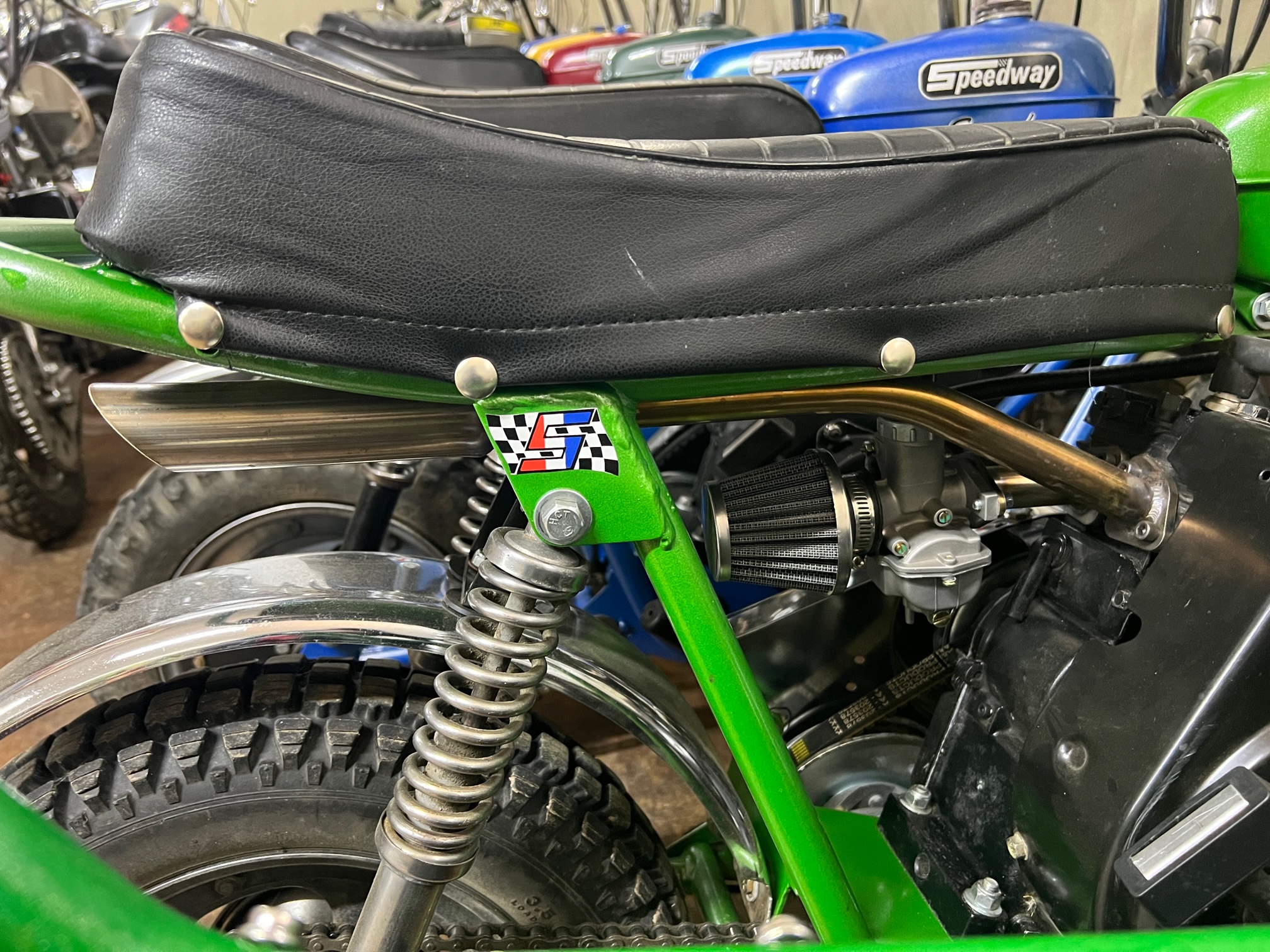
This Speedway Scarab also has a custom stainless steel exhaust that
bends to the side. This is a bit more difficult to make than the exhaust
shown above. The 1-3/8 inch "Harley" end
is not bent, but the way it is cut it looks bent. Surprisingly this exhaust
is not as loud as the straight exhaust pictured above. That's because the
bend out the side breaks up the sound a bit. I prefer this style of exhaust
as it has less surface area to accidentally grab when moving the bike after usage.
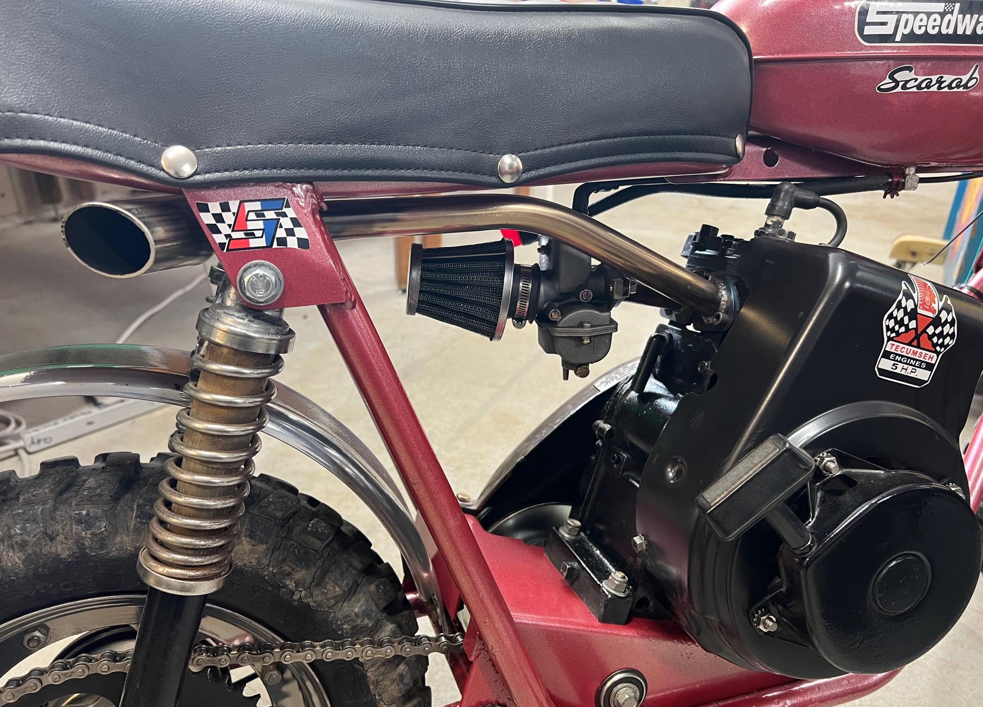
-
Note the two custom stainless steel exhausts in the above pictures.
These are good looking open exhausts, that will give maximum performance.
Because they are about 2 foot long, they must have an attachment support point.
On motors 5hp and less, you can use the frame (in this case the upper right
rear shock bolt) as a support point. On motors greater than 5hp, you will
need to have a spring style support or a support on the motor. If you use
a frame support, for sure the support will crack off the exhaust pipe. Motors
greater than 5hp just move too much during acceleration, and a fixed support point
for the exhaust on the frame just won't work.
26. Measuring RPM.
-
If you have done any performance mods and deleted the governor,
it would be nice to know what RPM your motor spins. Unfortunately
there isn't a good inexpensive tachometer. There are however
inexpensive tachometers out there. Now how good they are, well,
I'm not sure. But they do provide some idea on what RPM your
Tecumseh motor is spinning.
An inexpensive tachometer available on ebay and amazon for
under $20.
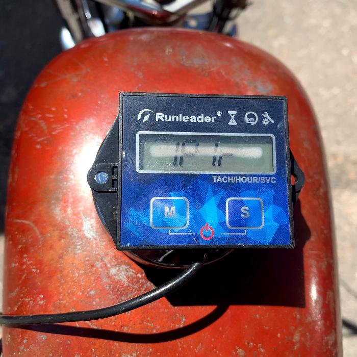
-
The cheap tachometers that you see on ebay and amazon I have
tested. I'm not sure of their accuracy, but they do give some
general ideas of motor RPM. To install one, you have to
wrap the tachometer wire around the engine's spark plug
wire, and hold it in place with a tie wrap (see picture below).
The number of turns around the spark plug wire is important.
I have found that six turns (as seen in the picture below)
seems to work best. Also these tachs need to be set to
"1P1r" (there are several setting based on number of cylinders).
Inexpensive tachometer available installed on the spark plug wire.
The number of turns around the wire is important. I have found
that six turns (as pictured below) seems to work best.
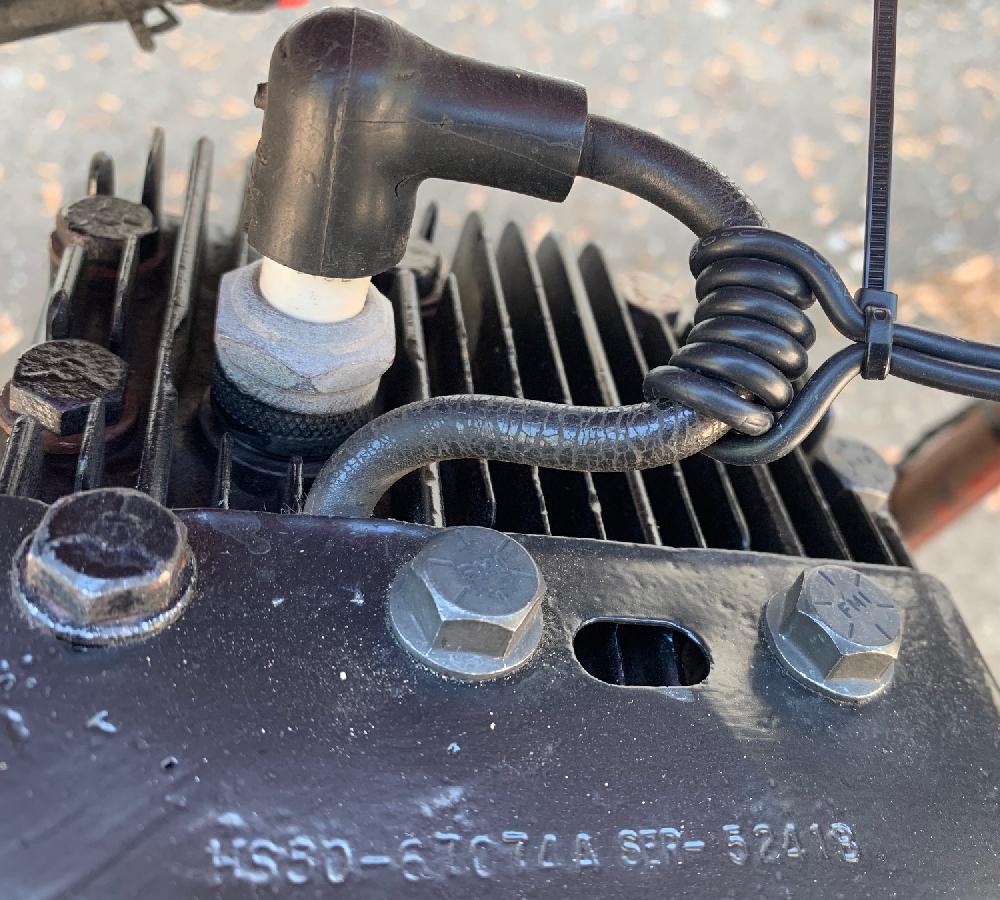
-
Again I'm not 100% sure these are accurate, but they do give
you an idea. For example my motors seem to idel at about 1600 rpm.
That seems fast to me (was expecting 1000 rpm). But at the higher
rpm's (full throttle), it seems they do appear to be fairly
accurate. Your mileage may vary.
27. Decals for the Blower Housing.
-
As a finishing touch, you'll need a few decals for the motor.
There's people on ebay that sell decals. These are good, but
they are water-slide style decals. Which means you have to
put some sort of durable clearcoat over the decal, or it
just won't last.

-
So what I do is to print the decals on sticky-back vinyl. This is
much more durable. And if the decal becomes damaged, I can just
peel off the old decal, and peel and stick another!
It's way easier to deal with than water slide decals.
- Tecumseh 5hp flags
- Tecumseh 4hp flags
- Tecumseh 4hp balloon (1970 and earlier)
- Air filter/Oil (points & condenser)
- Air Filter/Oil (electronic)
So how do you make vinyl decals? I have all the graphics available in Photoshop format for download on my minibike webpage. For example:
The "balloon" decal was used on the 1968-1970 Tecumseh HS40. All Tecumseh HS40 and HS50 motors from 1970 to 1978 should used the "flags" decals. After 1978 the rectangle Tecumseh logo decal was used (boring). Since the HS50 wasn't introduced until 1972, and you're putting it on a 1970s minibike, go with the "flag" decal. The air filter/oil decals can go on any motor if you like.
28. Conclusion.
-
As you can see, a decent snowblower Tecumseh HS style engine can be
converted to mini bike format. Is it easy? Yes and no. I guess it depends
on your skill set. But I have found following this document a great way
to get a vintage style motor (like I remember from my youth) inexpensively
for a 1970s minibike.
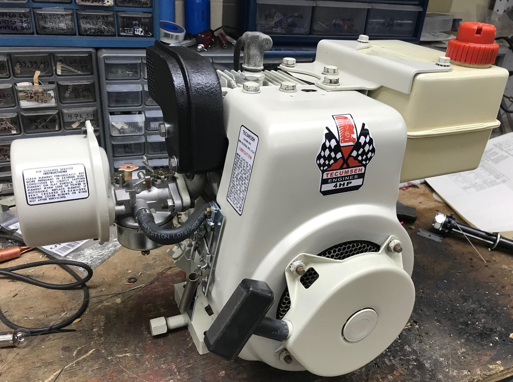
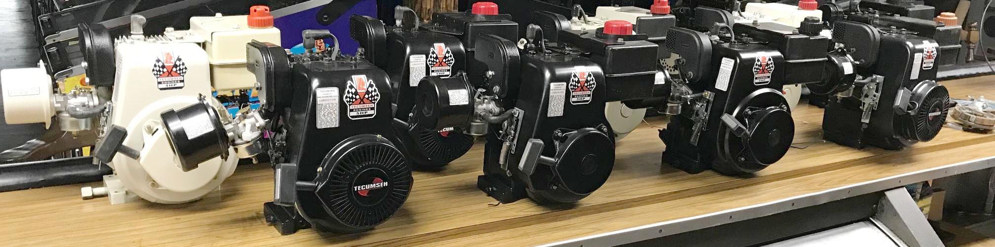
-
Note you don't have to go nuts when re-doing a snowblower motor. Below is a picture
of a dark grey snow blower motor. All I did was powdercoat the removable metal
pieces to black, and clean the long block with a degreaser and some rags.
I did *not* repaint or blast the long block (it is still sporting
its original dark grey color.) This worked out really well too, and was a lot less
paint/prep work!
Here's the same motor "after". From dark grey to black on this HS50 motor,
it's now ready for a minibike!