Nuova Bell pinball CPU board repair (Bell Cobra.)
![]()
Original written by Leon.
Updated by CFH, 8/15/2022
Nuova bell was mostly know for their tranformer kits, where they adapted older used machines by putting an new playfield and a new backglass into an excisting machine , where the boards and game rom was the one from that older machine. Mostly Bally machines where used.
A more elaborated article about Nuova
Bell can be found at these websites
here![]() and
here
and
here![]() .
.
The board described here is of course one of the later types made by Nuova Bell, with a complete other lay-out. Althought many caracteristics of the Bally board are to find on this board . Also two PIA's , an interrupt timer build around the NE555, the zero cross circuitry is also starting from the unregulated 43 volt .They use only half of the capacity of the memory , only 4 data bits as in the 5101 by Bally. Selection addresses of both PIA's are the same as these on the Bally board 0080 and 0090 . The start-up test indicated by 7 flashes of the on-board LED, are the same as in the Bally machines. All this gave me the opportunity to convert quickly the Bally test eprom and adapt it for this CPU board.
Short video of Leons COBRA machine (youtube.)
Note the Bell Cobra can *not* be strapped for 120 volt line voltage.
In order to use this game in North America, a 500watt 120/240 volt
conversion transformer is needed.
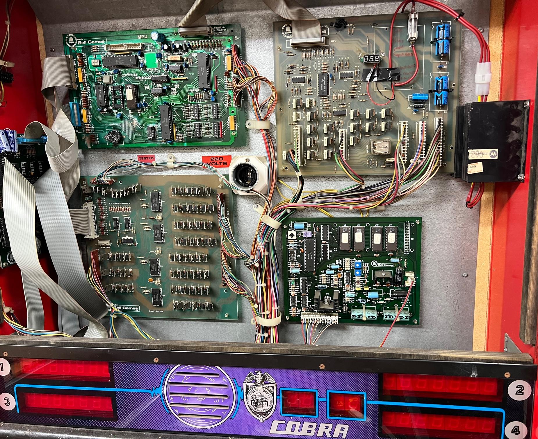
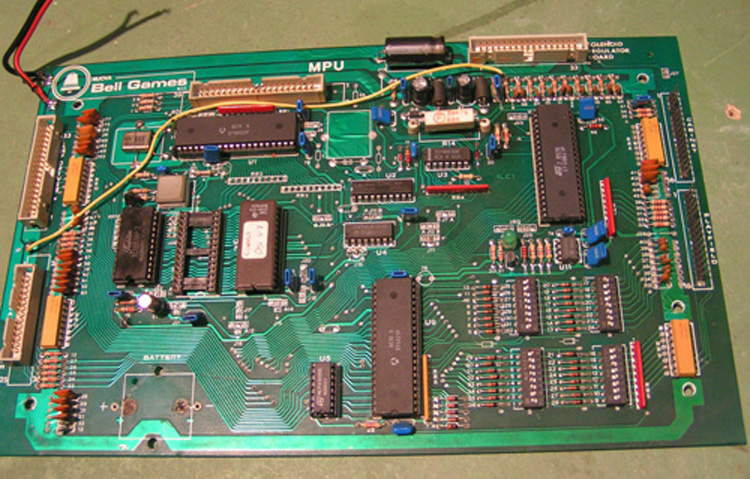
All boards in the head of the machine (except the transformer/power module, which
is in the lower cabinet):
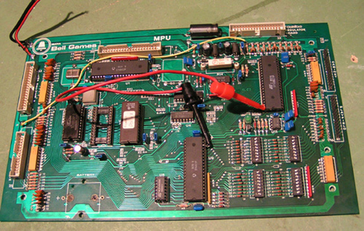
upper left the CPU board, upper right the solenoid/power board,
lower left the lamp driver, and at the lower right the sound board.
The display driver sits on the left side panel of the backbox.
Bell Cobra backbox boards.
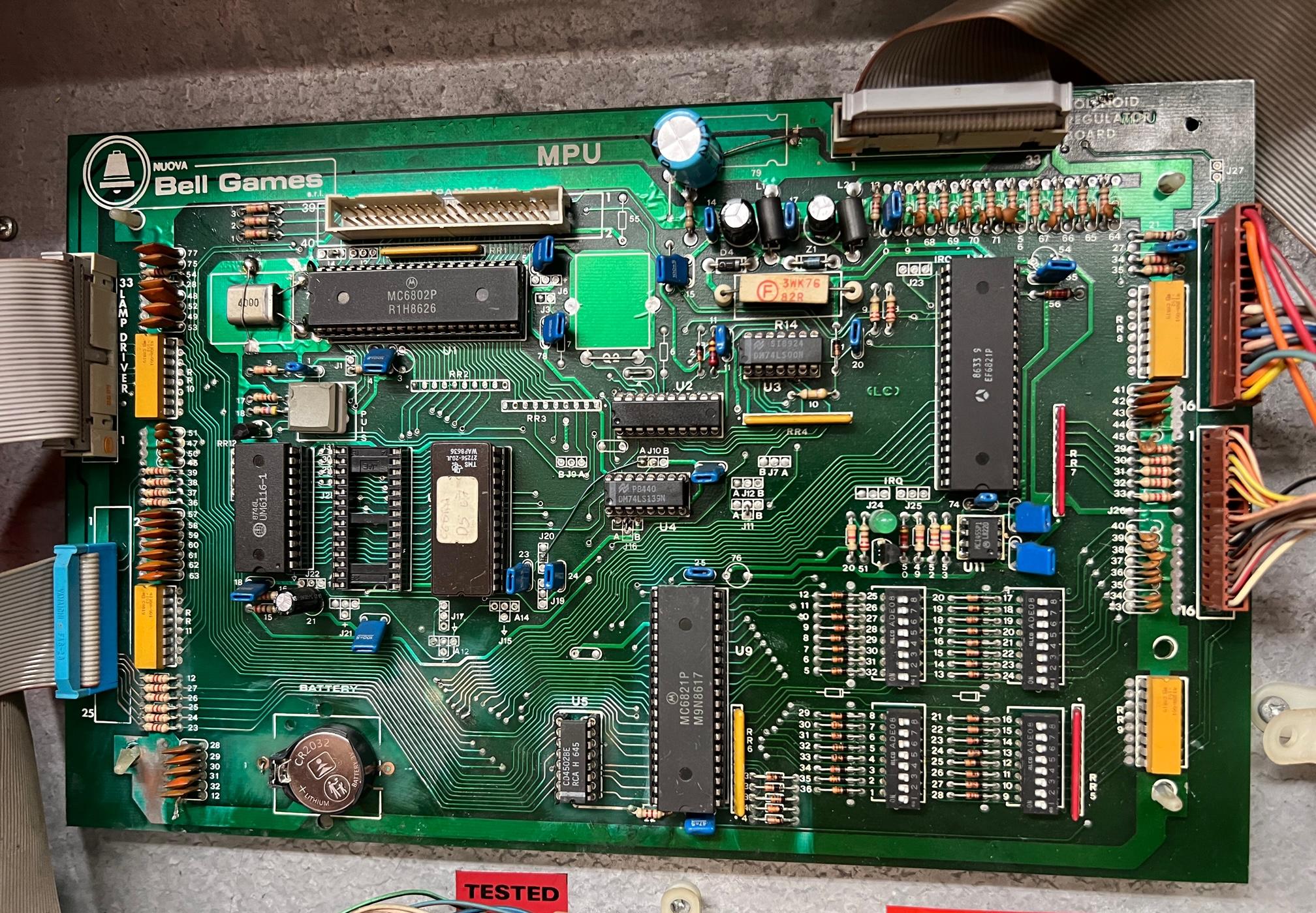
Bell Cobra CPU board with replacement cr2032 coil battery and blocking diode.
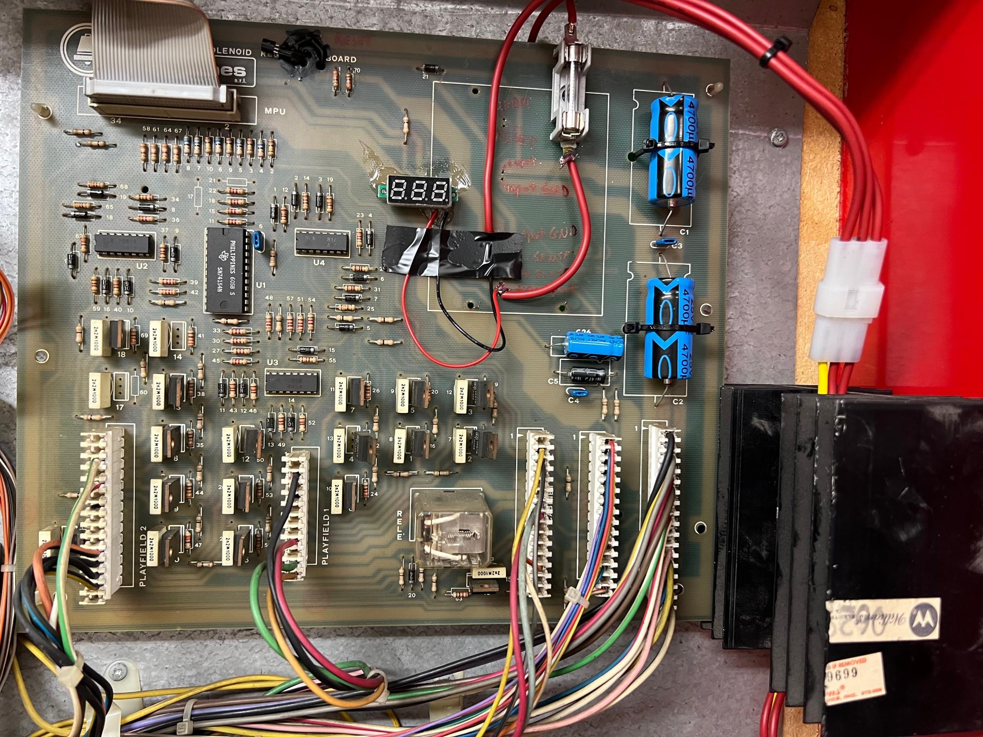
Solenoid driver board with the LM323 five volt modification and added 5vdc digit display readout.
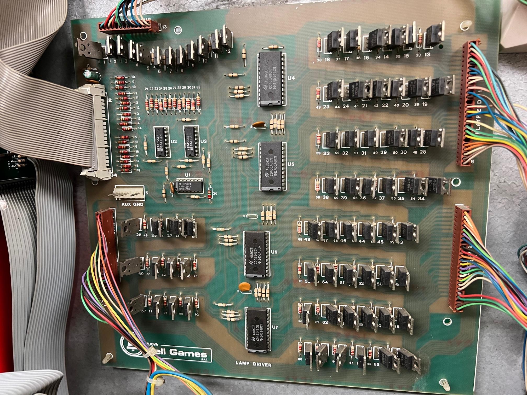
Lamp driver board.
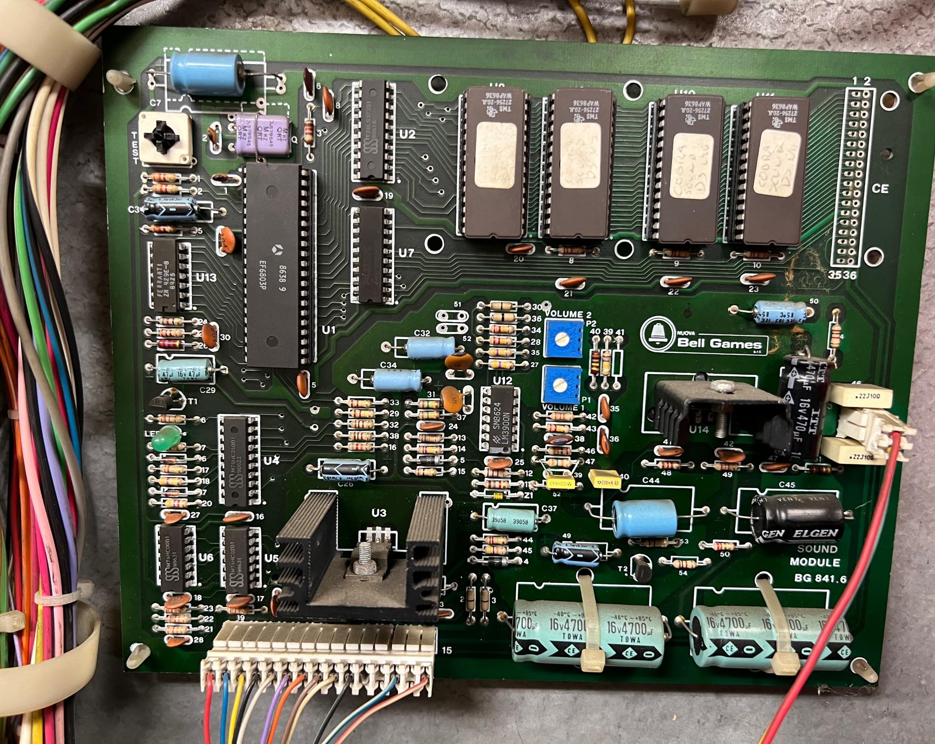
Sound board.
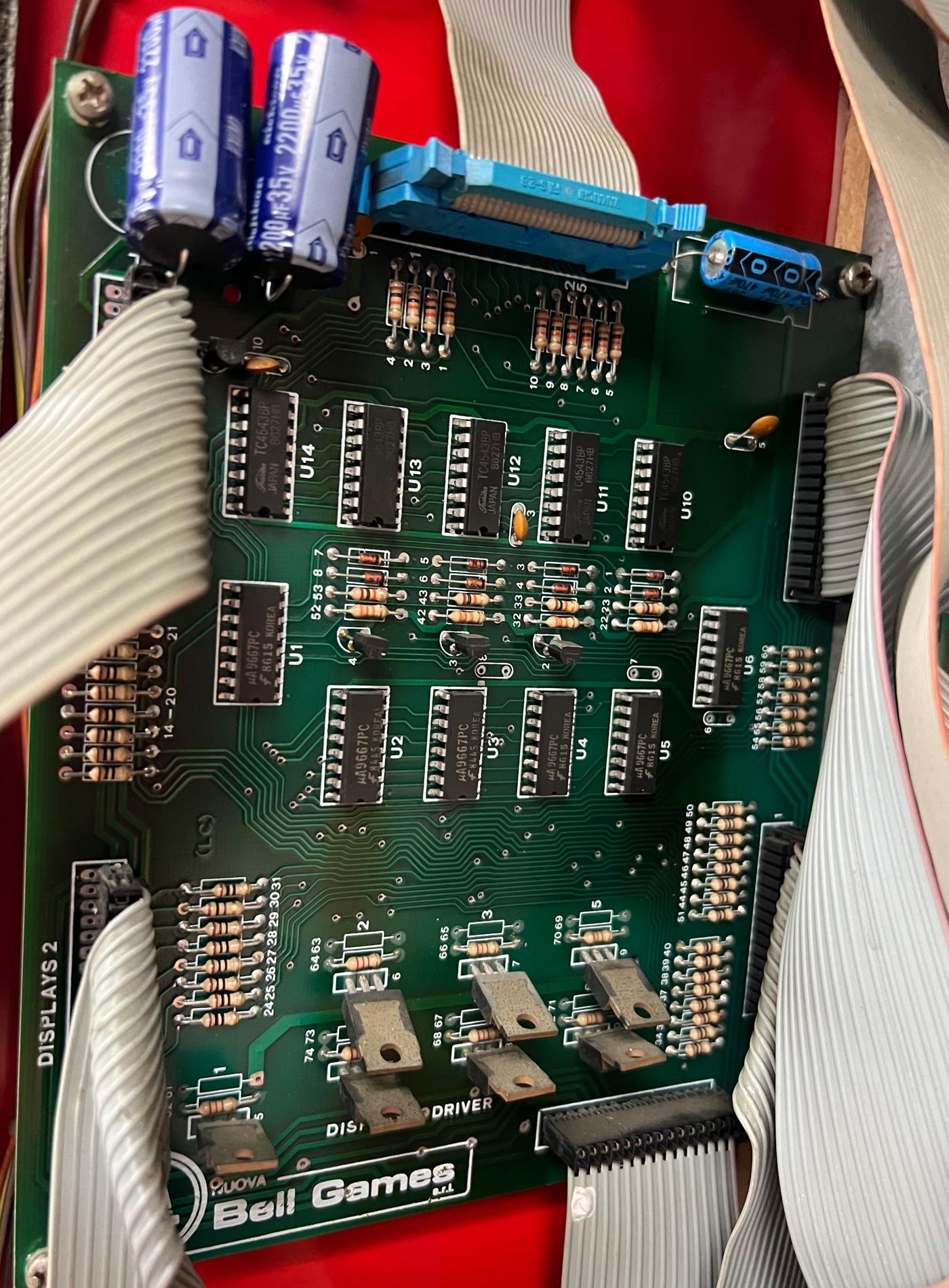
Display driver board.
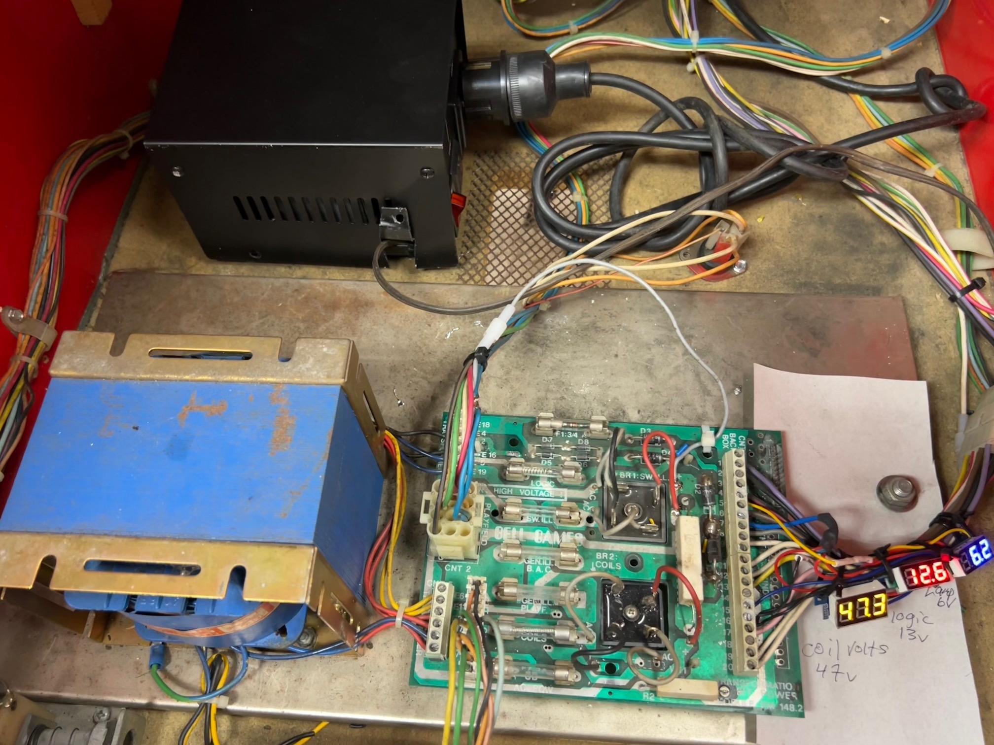
Bell Cobra Lower cabinet power module with 120 to 240 volt power transformer (black box.) Note voltage
display readouts have been added to the power module for 47 volts (coils), 13 volts (ultimately +5 volts), and
6 volts DC (cpu controlled lamps.)
Schematics for Bell Cobra and EPROM images:
![]()
Repairing the MPU Board.
To repair the Bell MPU board we can take it out the machine and boot it on the bench. To do this all we need is +5 volts. There are no test point loops on the MPU board for +5v and ground, so add them. I also add a test point loop for Reset and the 43vdc coil voltage (used for zero cross and the 7th MPU flash, if you have that voltage on your bench, most people do not.)Because the reset signal comes from the solenoid driver which is not available on the work bench (which we will need to add +5 volts when we boot the MPU board), it is handy to have a +5v test point loop on the MPU board. Again I add a test loop at the upper left corner of the MPU board for both ground and +5vdc (see picture below.) But you can also use the upper side of resistor R19 for +5 volts. But since the connectors are very small it best to solder a test point loop for ground and +5v and use those (again see picture below.) The outer run at the left side of the MPU board is the ground, and the inner run next to it is the +5vdc. Again I put test wire loops soldered there for ease of testing. I also like to add a wire loop for the reset line going to U1 pin40 of the 6802 processor.
The reason for adding the reset line test point is there is NO reset circuit on the MPU board! Instead, for some bizarre reason, Bell decided to have the reset on the solenoid driver board. This is why that "black box" on the solenoid driver board is so important... and unforunately fails! See below for repair notes on converting that black box to an LM323 and a DS1811 reset chip. The reset test point is just below the top most ribbon cable connector, and goes to a J4 jumper, and ultimately to U1 pin40 (6802 reset line.) You will need that test point to get the Bell MPU board to boot on your work bench!
The +5 and Ground test point wire loops added to the MPU board, for easy power hook ups when testing. Also a test point look is added for the 6802 pin40 reset line at jumper J4.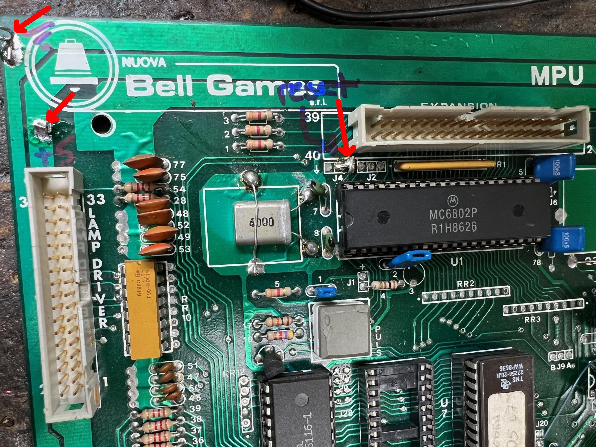
To power up the MPU board, all that is needed is a +5 volt power supply and ground.
BUT you will need another jumper wire connected to +5 volts. Turn on the power,
and the MPU LED will come on and stay on. Now take your +5 volt alligator clip
and connect it to the 6802 pin40 test loop. At this point you should see the MPU LED
starting to flash. You will get a total of six LED flashes if the board is working...
And if you have +43vdc at pin24 on the upper ribbon cable, you will get the 7th MPU
LED flash, and the MPU board should be fully booted.
Now if you are not getting all six (or seven) of the MPU board LED flashes, it's
time to use the Leon test EPROM.
Download the image of the Leon test EPROM
here ![]() and copy it to a 27256 eprom.
and copy it to a 27256 eprom.
Please check if the jumpers are the
same as indicated on the schematic, I had only one CPU board and
I'm not shure the game rom is always a single 27256 in socket U7.
If that is the case it's sure the test eprom will work, if there
is another type of game rom then it is needed to change the
jumpers to use the test eprom.
Note the Bell CPU board test LED flashes just like a Bally -35 CPU LED.
That is a (long) flicker at first, followed by seven LED flashes.
Each represents a test:
So same as bally, in fact, it's the bally code stolen from one of their games and hacked.
The Leon test is very similar as the Bally
test, we first will test the both PIA's , if these are ok we
check the memory.
![]()
Start .
To check if the test program runs properly we connect a test led at pin 15 of U1 ( cpu)
The test led is a normal led in series with a 1000 ohm resistor.
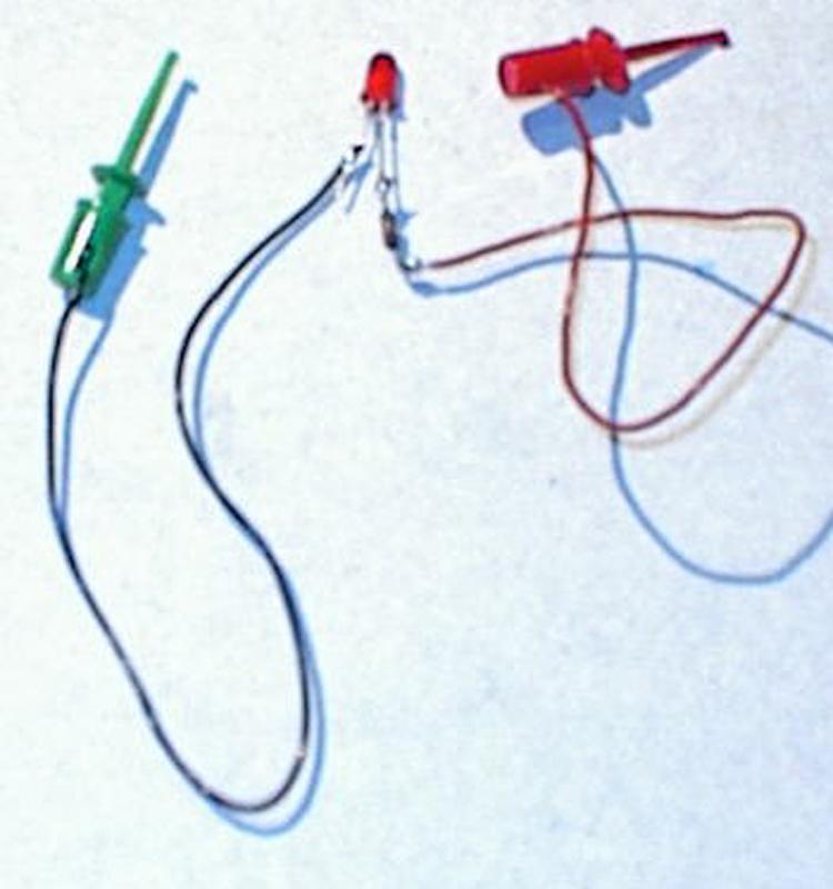
Connect the test led at pin 15 of U1 and the other lead at +5 volt.
Afther applying the tension on the board we reset it manually , connect pin 40 of IC 1 ( CPU) for a brief moment at ground. If all goes well both the test led and the on-board led will start blinking.
Now check with a voltmeter or logic tester that all outputs of both PIA's U9 and U10 are dancing between 0 and 5 volts ( the needle of the voltmeter will swing) . If there is an output that is not going from +5 to 0 lift that pin and check again , if its ok now the PIA is ok and there is a short on the output line , if it is still not ok the PIA is bad. This ends the output tests. ( Output pins are 2 to 17)
Memory Test.
To start the memory test push on the square push button located on the board. The led stops blinking for a very short wile and will restart . If it restart the memory test passed ok . If not the led will stay on or off, no more blinking. In this case the test still runs and tries to write and read . We can check wich signal is missing, all data signals and address signals have to be present, and also the selection signal, we need to find following values:
Memory IC is at U6.
Pin 14, 15, 16, and 17 ( only 4 data bus outputs used) = 2 volts.pulses
pin 18, select signal = 3 volts pulses
Pin 1,2,3,4,5,6,7,8,19 address bus signals = 2 volts pulses
pin 24 = +5 volts steady.
pin 22 1,5 volts pulses.
If the values are correct the memory IC is bad, if there is a signal missing check with the schematic where it has to come from and follow the signal "upstream" to find out where it get lost.
![]()
Test does not run at all.
When the test does not run at all, meaning that the LED connected at pin 15 of U1 does not blink afther the manual reset, we will remove the useless test eprom , without any program present restart the board with a manual reset . The following basic signals must be present now: On the CPU U1 pins 2,3,4 and 7 = 5 volts, Pin 5 = 3 volts. All address and data pins must pulse, you will find values between 1,5 and 3,5 volts. The data and address bus pins are from 9 to 33 ( except pin 21 wich is the 0 volt) On the selection pin of the eprom U7 ( socket ) there must be about 4 volts ( pulses) . If any of the signals is missing , as always bend upards that pin,measure again , and if the signal is there you have a short somewhere on that line , if one of the data or address signals is still missing the CPU IC is bad , the same if there are no signals at all or if the clock signal is missing at pin 38/39.
![]()
Last Test: 7th MPU LED Flash.
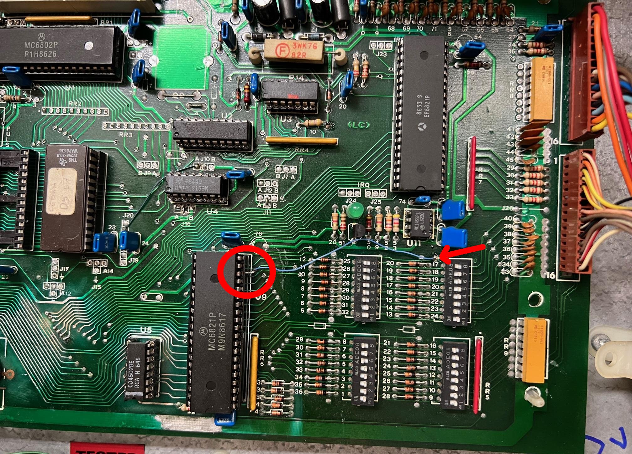
When the board on the bench with +5 volts, we can test the board using the game software. To do this have the game ROM installed and power up the board, and do a manual reset (using +5 volts applied to the reset test point after power on.) The board should boot and give six MPU LED flashes. The 7th LED flash is missing because there is no 43 volts on the bench, which normally comes from the solenoid/power board. If you want to see all seven LED flashes, we can fake out the board by lifting U9 pin18 (6821 PIA) and make a temporally connection with U10 pin40 (6821 PIA.) This essentially makes U9 pin18 high, and it will fake-out the software into giving the seventh LED flash, as done in a normal boot in the game. After the seventh LED flash, the LED will glow steady and faintly.
Adding a test point loop to the MPU board to supply 43vdc at the top of R13, if you have that voltage available on your work bench. Most people do not, and hence use the "fake-out" jumper to U9 pin18 to get the 7th LED flash.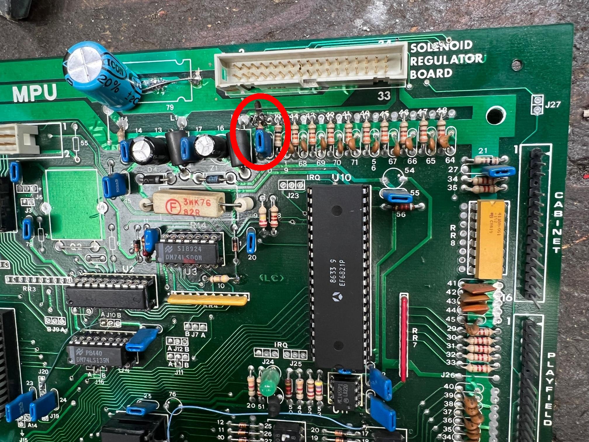
Adding a jumper from the lifted pin of U9 pin18 to U10 pin40. This "fake-out" the
software into giving the 7th MPU LED flash at boot-up. Pic by Leon
Here's another way, I guess a bit more permanent way, to add the jumper
between U9 pin18 and U10 pin40, using blue wire wrap.
The tests included in the game rom are similar of these of Bally. You can find the meaning of the several flashes in Bally articles . I recommend the Bally repair pages at pinrepair.com.
![]()
The Solenoid Power Board.
On the board we find a "black box" with this box contains the 5 volt regulator and the MPU board's reset circuit. As the box is completely sealed, it can not be repaired when it fails. And of course you will never find a replacement "black box", so we need to come up with a solution to this problem.
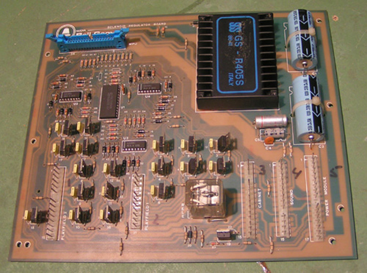
The solenoid power board with the famous black-box.
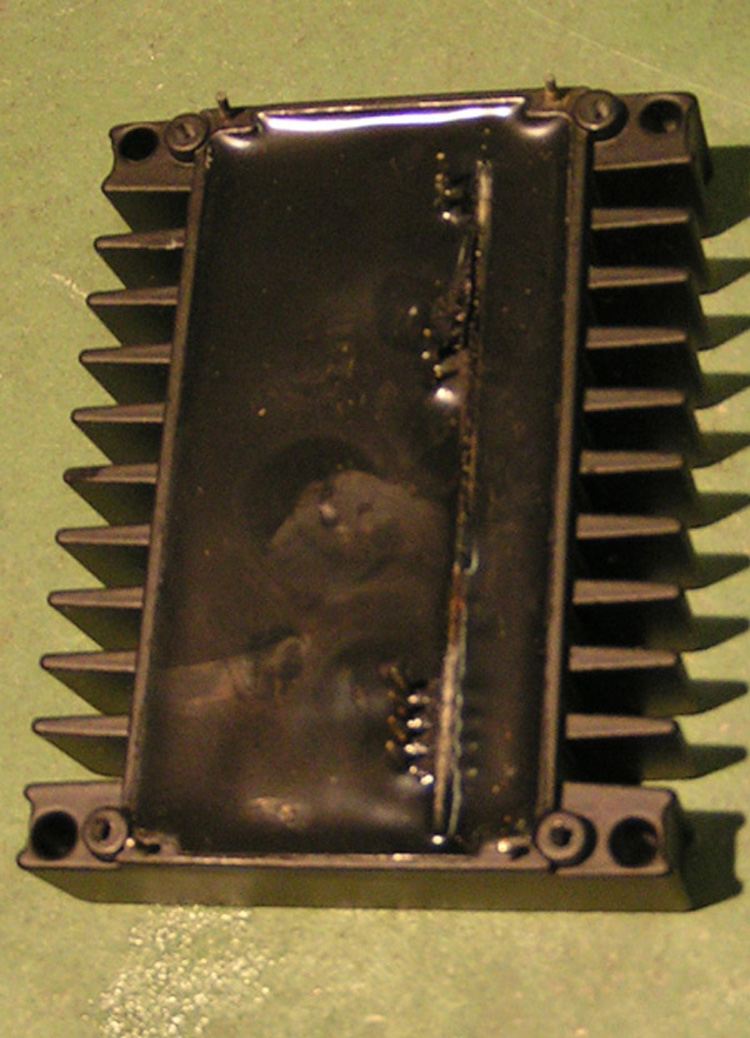
Completely sealed with epoxy. Signs of melting .....
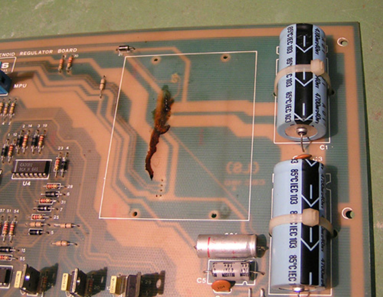
As you can see mine was bad, traces of melted material on the board .
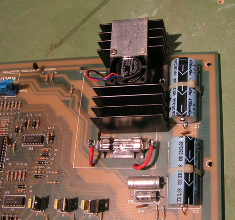
The 5 volt regulator was replaced by a LM323 on a cooler block, with extra mini-fan.I added a extra fuse on the 5 volt output. You need to drill some extra holes to mount the LM323, the wires for the fuse and ventilator are passing throught excisting holes.
The reset cirquitry is replaced by a
special reset IC, find the datasheet here ......
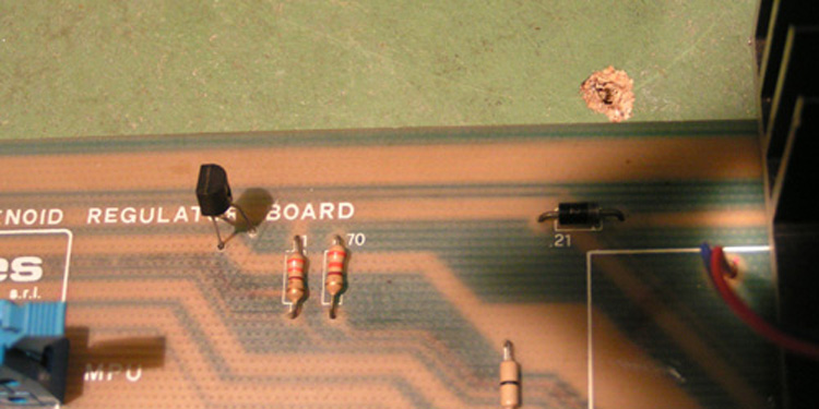
![]() The IC looks like a small transistor, and is
connected at 5 volts and the thirt lead is the output wich gives
+5 volt afther a short delay at power up.. The IC is placed near
R70 and R1 where two runs , the 0 and the +5 are close , so all
what there is to do is drill two fine holes and fix the IC ,the
thirt lead is connected at pin 22 of the MPUconnector. There are
several type of special made reset IC's you can use another type
as well as this DS1811.
The IC looks like a small transistor, and is
connected at 5 volts and the thirt lead is the output wich gives
+5 volt afther a short delay at power up.. The IC is placed near
R70 and R1 where two runs , the 0 and the +5 are close , so all
what there is to do is drill two fine holes and fix the IC ,the
thirt lead is connected at pin 22 of the MPUconnector. There are
several type of special made reset IC's you can use another type
as well as this DS1811.
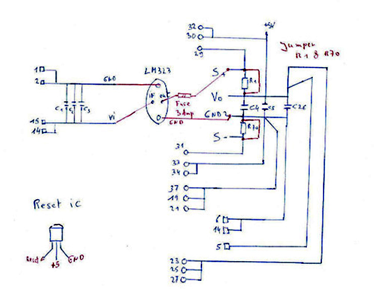
Find here a part of the solenoid -power board schematic and how to insert the new regulator and the reset IC. The red parts are the adaptions , the rest is the original schematic.
Replace the "black box" Cobra 5volt module with an LM323.