|
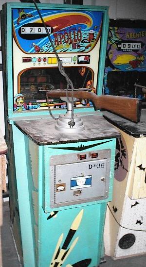
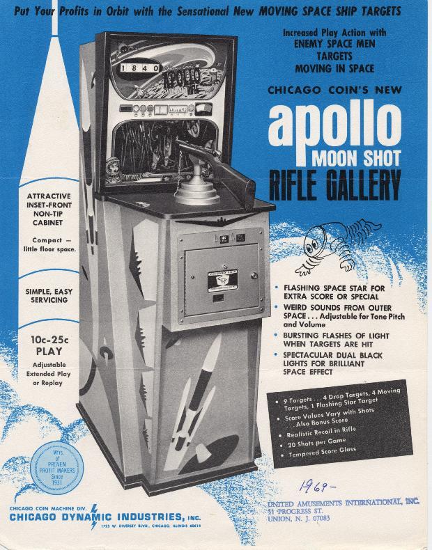
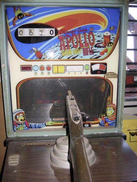
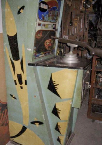
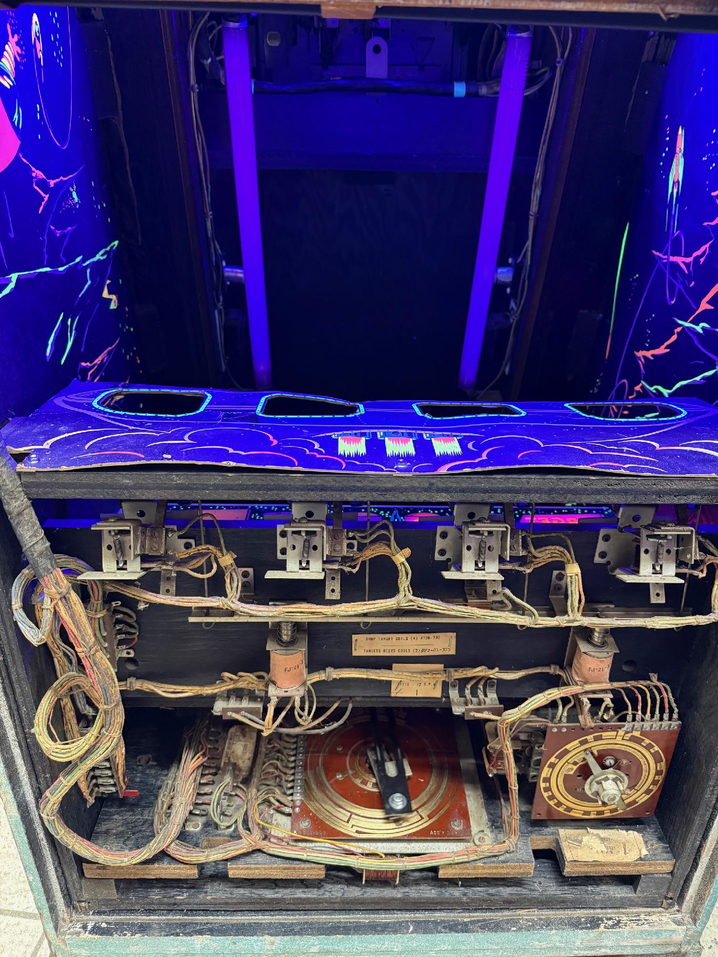
Description: Apollo Moon Shot Rifle Gallery, Chicago Coin, 1/69, electronic sound and bell sound. All the points scored use a single bell for sound (each 10pts is a bell hit.) But the X10 space ship (top moves left to right) uses a space sound as it flys from left to right (though hitting the X10 uses the bell for scoring sound.) Separate tone and volume control on the sound board. Point values change from shot to shot. There is also a stationary flashing star that is 300 points. Hitting the X10 can be worth as much as 300 points also. There are five stationary targets (including star) plus four moving targets. Game is 20 shots, unlimited time. Rifle recoil and a knocker used for gun shot sound. The X-10 sound board is really simple, using the 6.3vac light power as it's input power through the top two pins of the 4-pin connector. That is half wave rectified through two 1v600p (1n4005) diodes and two 470mfd caps, producing about 7.5vdc power for the sound board. From there it goes to two metal case transistor (one large, one small), neither marked! It's like whomever designed the board did not want you to know their secret sauce (there's no CCM provided schmatics.) The sound board, at game start, makes a solid pitched noise. This is output with one lead directly to the speaker, and the other output lead to the #3 pin of the 4-pin connector. The #3 pin goes to the motorized target animation unit. This acts as a switch to turn on the sound volume only while the X-10 space ship appears. The speaker output then goes from the animation unit to #4 (bottom most) connector pin, which then goes to the other lead of the speaker. Therefore the output sound from the sound board is turned on only when the X10 appears to the player, giving a spooky sound for the X-10. Note if you want to hear the sound board tone constantly as a test, just aligator lead pins 3/4 of the 4-pin connector and start a game. Unfortunately the X-10 sound board is often missing or broken. I suspect, besides the filter caps/diodes, the culprit is either or both of the metal cased transistors. Since we do not know their part numbers, it's hard to repair the sound board. Because of this you can use an inexpensive MP3 player with a constant, say 3 minute sound, that runs at MP3 board power-on. Just route the MP3 speaker output like the original sound board - One speaker lead to pin#3 on the 4-pin connector. The other MP3 speaker lead goes directly to the speaker. Power for the MP3 player can come from the 6vac just like the original sound board (top two pins of the 4-pin connector, blue and green.) Just run that 6.3vac through a bridge rectifier with a 1000mfd filter cap for the MP3 sound board power of about 7vdc. Depending on the MP3 board, may need to knock the power down closer to 5vdc using several 1n4004 diodes in series. I used a DY-SV17F mp3 sound board with TXD/io0 tied to ground and this 00001.mp3 sound file. It works very well and simulates the original X10 sound. Please contact me if you have this game for sale at cfh@provide.net
|
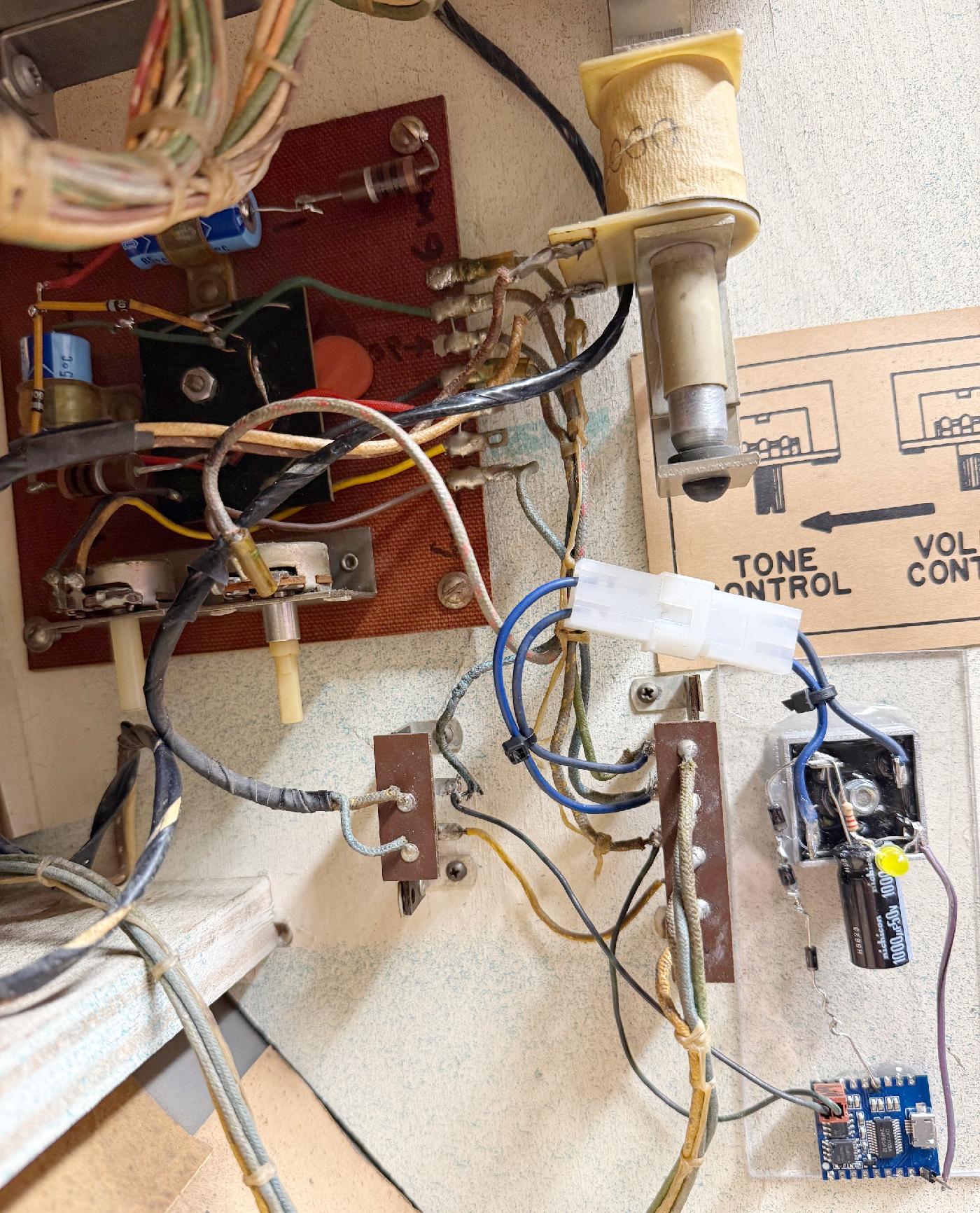
Using a DY-SC17F mp3 sound board to replicate the broken original sound board.
Three 1n4004 diodes in series to decrease the voltage going to the mp3 board down to 5vdc.
Also installed an LED on the bridge to show power on, with a 220ohm resistor.
|
* Email the collector cfh@provide.net * Go to the EM Arcade History index * Go to the Pinball Repair/History index |